Art Gallery Positioning System - Brown University
12
Art Gallery Positioning System Kaveh Boghraty May 17, 2007 1 Introduction The Art Gallery Positioning System is part of a larger project called Sonic Gallery 1 . Although this tracking system was built around the re- quirements of Sonic Gallery, the methods that are used can be adapted to a wide variety of sce- narios. Before a detailed description of the sys- tem, a little information about its development context is needed. 1.1 Sonic Gallery The vision of the Sonic Gallery project con- sists of an art gallery that uses location- dependent music to enhance a person’s under- standing and enjoyment of the visual works of art displayed in the gallery. Visitors of the gallery are provided with a small Pocket PC with head- phones, and upon approaching a painting, a cor- responding piece of music gradually immerses them in a state of mind that is more charac- teristic of the theme of the artwork. Among other factors, the implementation of this vision depends on the capability of simulta- neously estimating the position of several peo- ple within a room. Despite the successful im- plementation of other indoor tracking systems, such as Cricket 2 , a less costly route involving network cameras was considered by the Rhode Island School of Design (RISD). However, de- spite the successful development of several meth- ods for tracking human movement using cam- eras, there is a shortage of methods that can track several people simultaneously and distinc- tively through one set of cameras. 1.2 Stereo Camera Triangulation With the appropriate calibration, two cam- eras placed next to each other with a significant amount of gap and facing the same way can pro- vide enough information to calculate the missing coordinate of an object (depth) relative to the 2D images provided. For this project the ma- jor challenge is to get the cameras to each locate the 2D coordinates of the same target point. By maximizing the gap between the cameras with- out losing too much field-of-view we can mini- mize the amount of error in the depth estimate caused by the inaccuracies of 2D tracking. 1. Master Project by Ha Tran - http:// www.cs.brown.edu/publications/theses/masters/ 2007/tran.pdf 2. MIT’s indoor location system http://cricket.csail.mit.edu/ 1
Transcript of Art Gallery Positioning System - Brown University
Art Gallery Positioning System
Kaveh Boghraty
May 17, 2007
1 Introduction
The Art Gallery Positioning System is part ofa larger project called Sonic Gallery1. Althoughthis tracking system was built around the re-quirements of Sonic Gallery, the methods thatare used can be adapted to a wide variety of sce-narios. Before a detailed description of the sys-tem, a little information about its developmentcontext is needed.
1.1 Sonic Gallery
The vision of the Sonic Gallery project con-sists of an art gallery that uses location-dependent music to enhance a person’s under-standing and enjoyment of the visual works of artdisplayed in the gallery. Visitors of the galleryare provided with a small Pocket PC with head-phones, and upon approaching a painting, a cor-responding piece of music gradually immersesthem in a state of mind that is more charac-teristic of the theme of the artwork.
Among other factors, the implementation ofthis vision depends on the capability of simulta-neously estimating the position of several peo-ple within a room. Despite the successful im-plementation of other indoor tracking systems,such as Cricket2, a less costly route involvingnetwork cameras was considered by the RhodeIsland School of Design (RISD). However, de-
spite the successful development of several meth-ods for tracking human movement using cam-eras, there is a shortage of methods that cantrack several people simultaneously and distinc-tively through one set of cameras.
1.2 Stereo Camera Triangulation
With the appropriate calibration, two cam-eras placed next to each other with a significantamount of gap and facing the same way can pro-vide enough information to calculate the missingcoordinate of an object (depth) relative to the2D images provided. For this project the ma-jor challenge is to get the cameras to each locatethe 2D coordinates of the same target point. Bymaximizing the gap between the cameras with-out losing too much field-of-view we can mini-mize the amount of error in the depth estimatecaused by the inaccuracies of 2D tracking.
1. Master Project by Ha Tran - http://www.cs.brown.edu/publications/theses/masters/2007/tran.pdf
2. MIT’s indoor location systemhttp://cricket.csail.mit.edu/
1

1.3 Goal
To demonstrate that the above method canpotentially be used as a solution to the demandsof the Sonic Gallery project, this project must re-sult in the successful tracking of subjects thougha single pair of cameras. Provided one pairof cameras can track the location of a subjectwithin its field of view, the expansion of thetracking environment through the addition of ex-tra sets of cameras is a trivial process.
1.4 Approach
After experimenting with a few different track-ing methods, the most successful and by far thefastest of these consisted in background subtrac-tion followed by color detection. Both stages in-volve the use of a threshold value that is very cru-cial in isolating the target without ruling it outas background. Among the unsuccessful routesexplored are shape detection using image deriva-tives and eigenvectors.
2 Equipment
2.1 Calibration Toolbox
This package by Caltech students, called Cam-era Calibration Toolbox for Matlab3, providesnot only a relatively straightforward program for
calibrating stereo cameras after placement, butalso a wide range of matlab functions that facil-itate interaction with the cameras. The calibra-tion process makes use of a checkerboard posi-tioned a many different angles in front of bothcameras.
2.2 Setup
The Art Gallery Positioning System consistsof four major categories connected by the wire-less network: the cameras, the locator program,the receiver program, and the Pocket PCs (notavailable for final demo). Here is a simple dia-gram illustrating the network links:
3. Courtesy of Caltech Vision Department,www.vision.caltech.edu/bouguetj/
2

Here is an overview of the equipment used in thefinal demonstration.
2.3 Cameras
The specific model of the two cameras used inthe tracking is D-Links DCS-900W. This modelcan be accessed by Ethernet as well as 802.11b(Wireless). For this project, the wireless inter-face was used. The settings were adjusted toprovide the maximum resolution of 640x480 pix-
els.
2.4 Wireless Router
The 802.11b router that connected all compo-nents was Apples AirPort Express Base Station.Since the network did not need to be connectedto the Internet, no cables were used in the setupof this project. The AirPort router was pluggeddirectly into the nearest outlet and setup wire-lessly.
2.5 Laptops
The locator program (Matlab) ran on a Ap-ple PowerBook G4, while the receiver program(Java) ran on a Apple Intel MacBook Pro.
3
2.6 PocketPC
Unfortunately there were no working Pocket-PCs available for the last demo. Instead, I mod-ified the receiver program so that it displayeda simple diagram showing the position of thepeople being tracked in relation to the cameras.This diagram is updated upon the receipt of eachset of coordinates from the locator program.
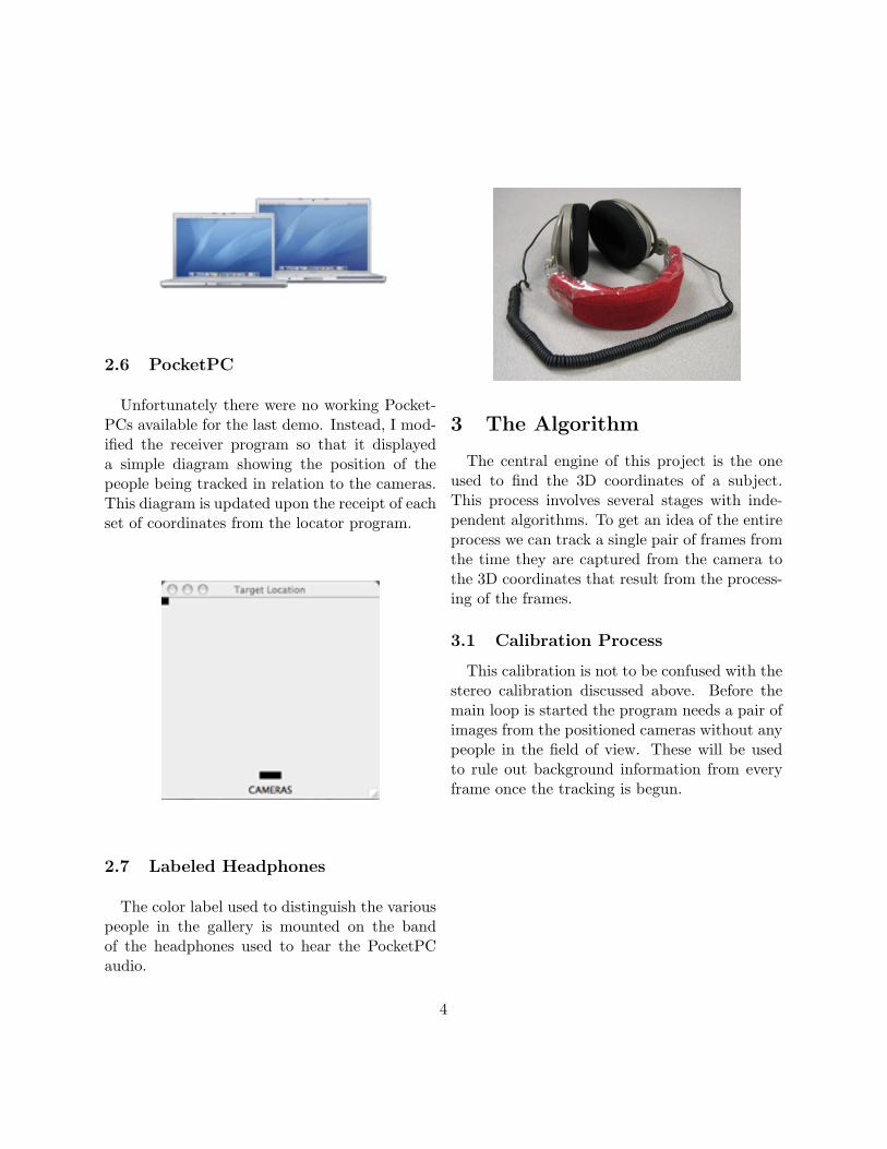
2.7 Labeled Headphones
The color label used to distinguish the variouspeople in the gallery is mounted on the bandof the headphones used to hear the PocketPCaudio.
3 The Algorithm
The central engine of this project is the oneused to find the 3D coordinates of a subject.This process involves several stages with inde-pendent algorithms. To get an idea of the entireprocess we can track a single pair of frames fromthe time they are captured from the camera tothe 3D coordinates that result from the process-ing of the frames.
3.1 Calibration Process
This calibration is not to be confused with thestereo calibration discussed above. Before themain loop is started the program needs a pair ofimages from the positioned cameras without anypeople in the field of view. These will be usedto rule out background information from everyframe once the tracking is begun.
4

3.2 Background Subtraction
Here is a typical frame as downloaded:
Background subtraction is a very efficient wayof reducing the chance of contamination from un-wanted objects with the same color of the targetlabel. In this part, the calibration frames storedbefore the tracking are subtracted from the newframes. If the new frames contain any new ob-jects, these will stand out in the resulting differ-ence of images. Since introducing a new objectin a scene also slightly changes the lighting inthe rest of the room, a threshold is used to al-low some tolerance in the difference values. Ifthe difference value of a pixel is higher than thethreshold, that pixel is considered for the colordetection process. The following image is theresult of subtracting the background from theabove frame (converted to grayscale):
There is no safe rule of thumb for the thresholdvalue, besides determination by trial. The valueof this argument is very important. If too smallof a value is chosen, the chances of contaminationfrom the background are substantial. If the valueis too big, the pixels of the target label can beunintentionally ruled out.
3.3 Color Detection
The pixels that survived the background sub-traction are organized into a list, and their x andy coordinates are saved. Each pixel has 3 values,one for each of the RGB colors. These can betreated as a set of 3D coordinates, so that the3D distance between this pixel’s color and thetarget color can be calculated.
A different threshold is used to determinewhich pixels are close enough to the target tobe considered for the Center of Mass. This time,pixel distance values greater than the thresholdare disposed of, leaving pixels with the colorsclosest to what we are trying to detect. Here isthe same frame after the color detection stage:
5

The border was added for display in this pa-per. Although this example shows a successfullocalization of the red headphone label, you canalso see that a substantial portion of the labelwas removed in the background subtraction pro-cess. This result hints that the difference thresh-old value is a bit too large ( leading to the re-moval of more than just background information).
3.4 Center of Mass
If the threshold values for the background sub-traction and color distance are not too far offtrack, at this point only the pixels correspond-ing to the label surface in the frames should beleft. The center of mass is calculated by aver-aging all the x and y coordinates into one set,which is then passed to the next stage.
3.5 Triangulation
At this point we have one set of 2D coordi-nates from each camera, corresponding to theposition of the target label. We can now use theCamera Calibration Toolbox for Matlab to ob-tain a set of 3D coordinates. The coordinates
returned by the triangulation function are notalways intuitive. For each stereo calibration, the3D origin that the coordinates are based on isdifferent. It is, however, fairly straightforward tofigure out the origin by running a few controlledtrials. The coordinates can now be transmittedto the receiver program.
4 Limitations
Although this tracking method is fast and re-quires fairly inexpensive equipment, it also hassome major drawbacks when compared to sys-tems using actual sensors. Below are some ofthe limitations that became frustratingly clearthroughout the project:
4.1 Subject Number
When using colors to distinguish multiple peo-ple within the same environment the maximumtarget number is very limited. Since a surface’scolor can vary in tone and brightness dependingon its position with respect to light, a certaindegree of flexibility must be allowed in the colordetection process of the tracking algorithm. Thismeans that in order to successfully distinguishvarious colors, they have to be distant enough onthe color spectrum so their detection ranges donot overlap. Moreover, depending on the setuplocation certain colors should be avoided becausethey are too common in the environment.
4.2 Subject Labeling
In order for the cameras to have a reasonablefield of view, they need to be fairly distant fromthe subjects. Consequently, the size of the colorlabels used to track the subjects needs to be large
6

enough so that it can be detected from that dis-tance. A large color label usually requires un-comfortable or unwanted extra clothing (hats)or accessories (large headphones). This may dis-courage people from making use of the trackingsystem.
4.3 Accuracy
There are numerous potential sources of in-accuracy in this method. Here are some of themost important ones:
• Items other than labels that match labelcolor range can lead to an incorrect centerof mass calculation.
• Line of vision from camera to label can beblocked by people or objects.
• Direct light source can cause the same la-bel surface to produce a wide range of colorvalues depending on position and angle withrespect to light.
• A large label surface area can cause a pairof cameras to focus on different points onthe same label and result in reduced trian-gulation accuracy.
Being familiar with the sources of inaccuracycan help adjust the environment to improve theodds. For example, a room’s light source canbe sometimes adjusted to create more ambientlight and less spotlight. Image difference thresh-old values, as well as label sizes, can be fine tunedfor specific conditions.
5 Conclusion
Although there is no way to significantly in-crease the limit of people that can be simultane-
ously tracked within an art gallery, the other ma-jor limiting factors can be minimized by tweak-ing the setup parameters ( camera positions,light source, ... ) to the system’s advantage.In other words, this tracking system could besuccessfully implemented as part of the SonicGallery project with a small number of people.This would be an inexpensive way to get an ideaabout the appeal of Sonic Gallery’s main conceptto various types of people, which would help de-termine weather it is worth it to further expandthe scale of the project.
References
[1] J.H. ter Bekke, The CricketLocation-Support system, Boston,MA, August 2000.
[2] Nissanka B. Priyantha, AnitChakraborty, Hari Balakrish-nan, Thinking Forth, a languageand philosophy for solving problems,Prentice Hall, ISBN 0-13-917568-7,1984.
[3] Klaus Strobl, Wolfgang Sepp, Ste-fan Fuchs, Cristian Paredes, KlausArbter,Camera Calibration Toolboxfor Matlab, Pasadena, CA
[4] Sturm and Maybank,On Plane-Based Camera Calibration: AGeneral Algorithm, Singularities,Applications, Reading, RG6 6AY,United Kingdom, 1999
7

Appendices
A Appendix A: Matlab codefor locator
A.1 locator.m
A.2 locate color.m
8

% = = = = = = = = = = = = = = = = = = = = = = = = = = = = = = = = = = = = = = = = = = = = = = = = = = = = = = = = = = =% locator.m% Kaveh Boghraty% = = = = = = = = = = = = = = = = = = = = = = = = = = = = = = = = = = = = = = = = = = = = = = = = = = = = = = = = = = = clear al l; % = = = = = = = = = = = = = = = = = = = = = = = = = = = = = = = = = = = = = = = = = = = = = = = = = = = = = = = = = = =% Please set the program parameters here% = = = = = = = = = = = = = = = = = = = = = = = = = = = = = = = = = = = = = = = = = = = = = = = = = = = = = = = = = = = % IP Address for camera 1 (left)cam1_address = ’10.0.1.31’; % IP Address for camera 2 (right)cam2_address = ’10.0.1.32’; % Directory where locator files are run frommain_dir = ’~/Desktop/locator/’; % Difference treshold: if pixel value difference between % calibration frame and current frame is smaller than this,% the pixel is ingnored for color detectionimdiff_cutoff = 0; % Color distance treshold: if 3D distance between target% color and pixel color is grater than this value, pixel is% not considered for center of masscolordist_cutoff = 40; % Debug on/off: set this to 1 if you want debug info, % including diff and color distance images to be displayedimdebug = 0; % Set this to 1 if you want to send coordinates to a server% of choiceserver_connect = 0; % Server IP and porthostname = ’10.0.1.2’;port = 2000; % = = = = = = = = = = = = = = = = = = = = = = = = = = = = = = = = = = = = = = = = = = = = = = = = = = = = = = = = = = = cd(main_dir); % Setup and initialize camerajavaaddpath ’./java/’;addpath ’./TOOLBOX_calib/’;import CamView; cv1 = CamView(cam1_address, 80);cv2 = CamView(cam2_address, 80);cv1.start();cv2.start(); % Wait for cameras to come online% Pause duration may need to be adjusted based on networkpause(5); % Setup and open connection to server

i f( server_connect ) socket = tcpip(hostname, port); fopen(socket);end % Load calibration filescaldir = ’./calibration/’;cal = load( [caldir ’Calib_Results_stereo.mat’] ); % load images in source foldersourcepath = ’./colors/’;colors = loadImagesRGB(sourcepath);h_size = size(colors);him1 = reshape( hats(2,:,:,:), h_size(2), h_size(3), h_size(4) );red = reshape( mean(mean(him1)), 1, 1, 3 ); % Load background calibration frames. Make sure there no temporary objects% or people in viewcalim1 = frame(cv1);calim2 = frame(cv2); out = ’0;0;0;’; while(true) pause(.25); % Receive frames from cameras fim1 = frame(cv1); fim2 = frame(cv2); % Subtract background diffim1 = imabsdiff( rgb2gray(fim1), rgb2gray(calim1) ); diffim1( find( diffim1 < imdiff_cutoff ) ) = 0; diffim2 = imabsdiff( rgb2gray(fim2), rgb2gray(calim2) ); diffim2( find( diffim2 < imdiff_cutoff ) ) = 0; % Find target in new frames [y1,x1, distmat1] = locate_color( fim1, calim1, red, tile, imdiff_cutoff, colordist_cutoff ); [y2,x2, distmat2] = locate_color( fim2, calim2, red, tile, imdiff_cutoff, colordist_cutoff ); % If target could not be located 0 is returned i f( y1 == 0 || y2 == 0 ) NAval = sprintf( ’%d;%d;%d;\r\n’, [0;0;0] ); % Send coordinates to server i f( server_connect ) fprintf( socket, ’%s’, NAval ); end % Print coordinates i f( imdebug ) fprintf( ’%s’, NAval ); end i f(imdebug) subplot(2,3,1) imagesc( fim1 ); subplot(2,3,4) imagesc( fim2 ); subplot(2,3,2) colormap gray imagesc( diffim1 ); subplot(2,3,5) imagesc( diffim2 ); subplot(2,3,3)

imagesc( distmat1 ); subplot(2,3,6) imagesc( distmat2 ); drawnow; end else % Triangulation happens here [XL,XR] = stereo_triangulation( [x2;y2], [x1;y1], cal.om, cal.T, cal.fc_left, cal.cc_left, cal.kc_left, cal.alpha_c_left, cal.fc_right, cal.cc_right, cal.kc_right, cal.alpha_c_right); i f(imdebug) subplot(2,3,1) imagesc( fim1 ); hold on; rectangle(’Position’, [x1!10,y1!10,20,20], ... ’Curvature’, [0,0], ’EdgeColor’, ’red’); subplot(2,3,4) imagesc( fim2 ); hold on; rectangle(’Position’, [x2!10,y2!10,20,20], ... ’Curvature’, [0,0], ’EdgeColor’, ’red’); colormap gray subplot(2,3,2) imagesc( diffim1 ); subplot(2,3,5) imagesc( diffim2 ); subplot(2,3,3) imagesc( distmat1 ); subplot(2,3,6) imagesc( distmat2 ); drawnow; end % Construct output out = sprintf( ’%d;%d;%d;\r\n’, (int16(XL)) ); % Send coordinates to server i f( server_connect ) fprintf( socket, ’%s’, out ); end % Print coordinates i f( imdebug ) fprintf( ’%s’, out ); end endend

function [y,x, distmat] = locate_color( fim, cim, color, tile, diff_tresh, dist_tresh ) % store image dimensionsimsize = size(fim); % expand destination color to size of imagecolormat = repmat( color, [ imsize(1), imsize(2) ] );% compute difference matrix of color and imagediffmat = double(fim) ! double(colormat);% compute distance matrix between image and colordistmat = ( (diffmat(:,:,1).^2) + (diffmat(:,:,2).^2) + (diffmat(:,:,3).^2) ).^(1/2); % use background image to narrow matchesdiffim = imabsdiff( rgb2gray(fim), rgb2gray(cim) );indeces = find( diffim < diff_tresh ); % discard values outside diff matchdistmat(indeces) = max(max(distmat)); % get all pixels with values close to destination color[y_vals, x_vals] = find( distmat < dist_tresh ); % for return image, remove all out!of!range pixels distmat( find( distmat > dist_tresh ) ) = max(max(distmat)); % make sure we have a matchi f(length(y_vals) == 0) x = 0; y = 0; disp ’No match’;else y = mean( y_vals ); x = mean( x_vals );end


![LEONARD BROWN - andrew-baker.com Brown_I Promised a Rainbow.pdf · Brown, Leonard, The Painters Gallery (statement and poem) [ex. cat.], Sydney, 28 August 1986 Brown, Phil, Mystical](https://static.fdocuments.us/doc/165x107/5fc2f222f84a607bd902bb82/leonard-brown-andrew-baker-browni-promised-a-rainbowpdf-brown-leonard-the.jpg)