ARO SKI & SPINDLE KIT - Polaris Inc.
8
APPLICATION The Timbersled ARO Ski and Spindle upgrade kit is designed to be a direct replacement to the Timbersled Backcountry ski and spindle. Fitment and fork clamps stay the same as what is called out for your specific bike make and model, there is no need to change any front install kit items for the ARO Ski and Spindle upgrade install. For details on the install kit for your specific make and model of bike visit Timbersled.com or scan the QR code if using a mobile device. If viewing on a PC click HERE BEFORE YOU BEGIN Read these instructions and check to be sure all parts and tools are accounted for. Please retain these installation instructions for future reference and parts ordering information. KIT CONTENTS The Timbersled ARO Ski & Spindle kit is designed to fit a variety of makes and models of bikes. Your specific install kit required (not shown) may vary slightly depending on make and model. REF QTY PART DESCRIPTION PART NUMBER 1 1 Ski Assembly - 11.5” Wide 1824633 2 1 Skag - Center 1824634 3 1 Skag - LH 1824635 Instr 9928592 Rev 01 2017-11 Page 1 of 8 P/N 2883418 ARO ™ SKI & SPINDLE KIT
Transcript of ARO SKI & SPINDLE KIT - Polaris Inc.

APPLICATIONThe Timbersled ARO Ski and Spindle upgrade kit is designed to be a direct replacementto the Timbersled Backcountry ski and spindle. Fitment and fork clamps stay the sameas what is called out for your specific bike make and model, there is no need to changeany front install kit items for the ARO Ski and Spindle upgrade install. For details on theinstall kit for your specific make and model of bike visit Timbersled.com or scan the QRcode if using a mobile device. If viewing on a PC click HERE
BEFORE YOU BEGINRead these instructions and check to be sure all parts and tools are accounted for. Please retain theseinstallation instructions for future reference and parts ordering information.
KIT CONTENTSThe Timbersled ARO Ski & Spindle kit is designed to fit a variety of makes and models of bikes. Your specificinstall kit required (not shown) may vary slightly depending on make and model.
REF QTY PART DESCRIPTION PART NUMBER1 1 Ski Assembly - 11.5” Wide 1824633
2 1 Skag - Center 1824634
3 1 Skag - LH 1824635
Instr 9928592 Rev 01 2017-11 Page 1 of 8
P/N 2883418
ARO™ SKI & SPINDLE KIT
Instr 9928592 Rev 01 2017-11 Page 2 of 8
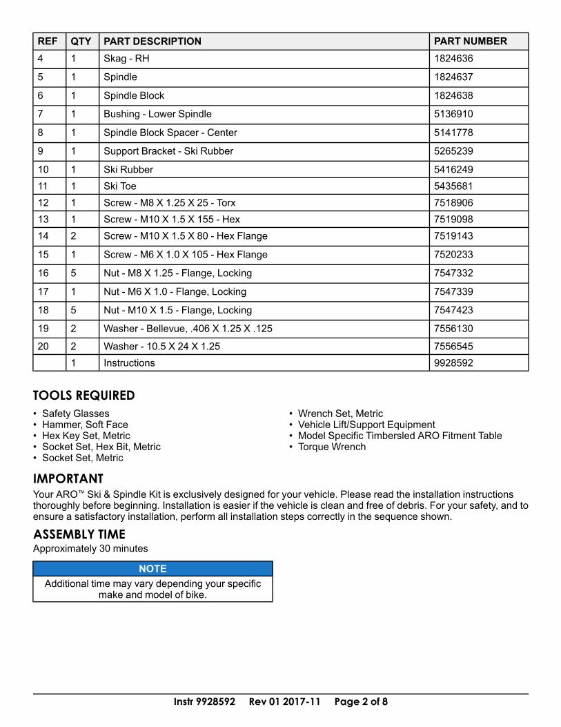
REF QTY PART DESCRIPTION PART NUMBER4 1 Skag - RH 1824636
5 1 Spindle 1824637
6 1 Spindle Block 1824638
7 1 Bushing - Lower Spindle 5136910
8 1 Spindle Block Spacer - Center 5141778
9 1 Support Bracket - Ski Rubber 5265239
10 1 Ski Rubber 541624911 1 Ski Toe 543568112 1 Screw - M8 X 1.25 X 25 - Torx 751890613 1 Screw - M10 X 1.5 X 155 - Hex 751909814 2 Screw - M10 X 1.5 X 80 - Hex Flange 7519143
15 1 Screw - M6 X 1.0 X 105 - Hex Flange 7520233
16 5 Nut - M8 X 1.25 - Flange, Locking 7547332
17 1 Nut - M6 X 1.0 - Flange, Locking 7547339
18 5 Nut - M10 X 1.5 - Flange, Locking 7547423
19 2 Washer - Bellevue, .406 X 1.25 X .125 7556130
20 2 Washer - 10.5 X 24 X 1.25 75565451 Instructions 9928592
TOOLS REQUIRED• Safety Glasses• Hammer, Soft Face• Hex Key Set, Metric• Socket Set, Hex Bit, Metric• Socket Set, Metric
• Wrench Set, Metric• Vehicle Lift/Support Equipment• Model Specific Timbersled ARO Fitment Table• Torque Wrench
IMPORTANTYour ARO™ Ski & Spindle Kit is exclusively designed for your vehicle. Please read the installation instructionsthoroughly before beginning. Installation is easier if the vehicle is clean and free of debris. For your safety, and toensure a satisfactory installation, perform all installation steps correctly in the sequence shown.
ASSEMBLY TIMEApproximately 30 minutes
NOTEAdditional time may vary depending your specific
make and model of bike.

Instr 9928592 Rev 01 2017-11 Page 3 of 8
INSTALLATION INSTRUCTIONS
The instructions listed are universal for all bikes usingthe Timbersled Ski & Spindle kit. The process in theinstructions may vary slightly between bike makesand models. Refer to your host bike’s owner’s manualfor specific references and assembly/disassemblyprocedures.You may also need a copy of your Timbersled FitmentTable for your specific bike model. Your TimbersledFitment Table can be found and printed at Timbersled.com or by contacting your local Timbersled dealer.FRONT END DISASSEMBLY1. Remove fork guards if installed and retain for later
use.2. Remove fork clamps and spindle support shaft.
Save to be reinstalled later.3. Remove axle nut. Loosen front axle pinch clamp
bolts and remove the front axle bolt.4. Remove the existing front ski/spindle assembly
from the bike. Make note of your previouslyinstalled front spindle spacers/reducers beforeremoval, these will be reinstalled with the newARO ski and spindle assembly.
SPINDLE INSTALLATIONNOTE
The Timbersled spindle is universal for all models ofbikes.
1. Reinstall the correct spacer/reducers for yourmake and model of bike into the left and right sideof the new ARO spindle cross tube.
NOTESee your Timbersled Fitment Table for your exact
bike model to see the correct spacer/reducerplacement. Some models have a 3-piece setup witha spacer/reducer on the left hand side with a tubestyle spacer that will fit into the center of the spindleand a washer style spacer on the right hand side.
2. Place the ARO spindle assembly into position withthe concave side of the spindle facing towards therear of the motorcycle. Slide in the stock front axlebolt (unless the fit kit is supplied with a Timbersledmachined axle) and install the nut. DO NOTTIGHTEN any of the front end fasteners at thistime.

Instr 9928592 Rev 01 2017-11 Page 4 of 8
3. Locate the inner fork clampsA and place themonto the inside face of the fork tubes in betweenthe fork tube and the spindle with the fork sealrelief groove facing up.
4. Slide both inner fork clampsA (less fork clampcap) down between the spindle and fork tubes.Position them as low as possible on the fork tube.
NOTESlide the brake-side clamp down on the fork tube aslow as it will go first, then set the opposing side.
Ensure that both left and right fork clamps are sittingat the same height.
5. Install the plastic split bushingB onto the forktubes above the clamps with the bushing flange onthe top. Slide the bushing down into the forkclamps so that bushing flange is all the way downinside the relief groove.
6. Rotate the spindle forward and back until the forkclamp bolt holes line up with the slotted spindleholes. This will properly set the correct amount oftrailing the ski will have in relation to the axle bolt.
NOTETo help hold the spindle in place while you work on ityou can snug the axle nut and set the spindle on theground. You can then tap the spindle back and forth
to get the correct positioning.
7. Place the outer fork clampsC onto the lowerassembly with the fork seal relief groove facing upand so that the split fork bushing flange is notpinched or crushed.
8. Insert the 2.75” x 5/16” bolt in the front fork clampbolt holes and the 3.0” x 5/16” bolt in the rear forkclamp bolt holes on both left and right fork clamps.

Instr 9928592 Rev 01 2017-11 Page 5 of 8
9. On the rear fork clamp bolts, you will use theincluded spindle support cross shaftD that the 3”bolts will thread into. This cross shaft will fit in-between the ears of the spindle and will providesupport to the assembly. Use the provided flatwasher and 5/16” lock nut on the inside of thespindle to secure the front fork clamp bolts. Torquethe front and rear fork clamp bolts evenly to thespecification listed below.
TORQUE25Nm (18 Ft. Lbs)
10. If re-installing bike’s stock front axle, see your bikemanufacturers owner’s manual for proper torquespecifications. If using a front axle provided in yourTimbersled Install Kit, torque the axle bolt to thespecifications below.
TORQUE45Nm (33 Ft. Lbs)
11. Tighten the lower fork tube pinch bolts to your bikemanufacturers specified torque settings.
12.Reinstall fork guards.
SKI INSTALLATION1. Install ski hoops onto ski by first securing the
front of the hoop to the front of the ski using theprovided fasteners,d/j. DO NOT TIGHTEN atthis time. Then line up the mounting hole on theback of the ski hoop with the mounting hole on theski as shown. Use provided fastenersh andk tosecure into position. Torque both front and rear skihoop fasteners,j/k, to specifications below.
TORQUEFront: 18Nm (13 Ft. Lbs)Rear: 6Nm (4.5 Ft. Lbs)

Instr 9928592 Rev 01 2017-11 Page 6 of 8
2. Next, place the ski rubber support plateD into thecenter cradle of the ski. Make sure the four lowerplate fingers drop fully down into the front two slotsF in the ski cradle as indicated with the top T-shaped ears of the plate facing towards the rear ofthe ski.
NOTEArrows indicate forward (front) direction.
3. Place the ski rubberE into the ski cradle with thelarge thick portion of the ski rubber facing the frontof the ski.
4. Place a coating of waterproof grease on the outerdiameter of the ski collarG. Install the ski collarinto the lower ski bolt hole of the spindle block.

Instr 9928592 Rev 01 2017-11 Page 7 of 8
5. Place ski, with ski rubber and ski rubber supportplate installed, under the spindle. Lift up on thefront of the ski to pull it up into place. Once inplace, push the ski bolt through belleville washers,ski cradle ears, and spindle cradle to hold the skiin place. Make sure the concave surfaces of thebelleville washers are facing in against the skicradle ears.
NOTEIt will be a tight fit between the ears of the ski
bracket.
6. Secure ski by installing the locking nutH onto skibolt and tighten. Torque nutH to specificationlisted below.
TORQUE45 Nm (33 ft/lbs)
WARNINGFailure to torque fasteners as directed will adverselyaffect the steering system and may lead to severe
injury or death.
7. Ensure all tools are accounted for and all stepshave been completed in the correct order.

Instr 9928592 Rev 01 2017-11 Page 8 of 8
FEEDBACK FORMA feedback form has been created for the installer to provide any comments, questionsor concerns about the installation instructions. The form is viewable on mobile devicesby scanning the QR code or by clicking HERE if viewing on a PC.
FEEDBACK FORM