
Functional Non-Coding DNA Part I Non-coding genes and non-coding elements of coding genes
Upload
safa4116684Category
view
223download
0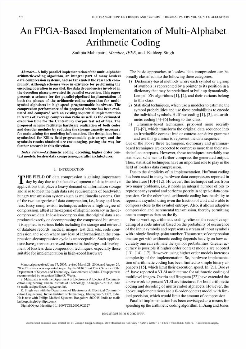
8/6/2019 Arith Coding
http://slidepdf.com/reader/full/arith-coding 1/9
1678 IEEE TRANSACTIONS ON CIRCUITS AND SYSTEMS—I: REGULAR PAPERS, VOL. 54, NO. 8, AUGUST 2007
An FPGA-Based Implementation of Multi-AlphabetArithmetic Coding
Sudipta Mahapatra , Member, IEEE , and Kuldeep Singh
Abstract—A fully parallel implementation of the multi-alphabetarithmetic-coding algorithm, an integral part of many losslessdata compression systems, had so far eluded the research com-munity. Although schemes were in existence for performing theencoding operation in parallel, the data dependencies involved inthe decoding phase prevented its parallel execution. This paperpresents a scheme for the parallel-pipelined implementation of both the phases of the arithmetic-coding algorithm for multi-symbol alphabets in high-speed programmable hardware. Thecompression performance of the proposed scheme has been eval-uated and compared with an existing sequential implementationin terms of average compression ratio as well as the estimated
execution time for the Canterbury Corpus test set of files. Theproposed scheme facilitates hardware realization of both coderand decoder modules by reducing the storage capacity necessaryfor maintaining the modeling information. The design has beensynthesized for Xilinx field-programmable gate arrays and thesynthesis results obtained are encouraging, paving the way forfurther research in this direction.
Index Terms—Arithmetic coding, decoding, higher order con-text models, lossless data compression, parallel architectures.
I. INTRODUCTION
T
HE FIELD OF data compression is gaining importance
day by day due to the fast development of data-intensiveapplications that place a heavy demand on information storageand also to meet the high data rate requirements of bandwidthhungry transmission systems such as multimedia systems. Outof the two categories of data compression, i.e., lossy and loss-less, lossy compression techniques achieve a high degree of compression, albeit at the expense of slight inaccuracy in the de-compressed data. In lossless compression, the original data is re-produced exactly on decompressing the compressed bit stream.It is applied in various fields including the storage and retrievalof database records, medical images, test data sets, code com-pression and so on where any loss of information in the com-pression-decompression cycle is unacceptable. Such applica-
tions have generated renewed interest in the design and develop-ment of lossless data compression techniques, especially thosesuitable for implementation in high-speed hardware.
Manuscript received June 17, 2005; revised March 21, 2006, and August 29,2006.This work was supported in part by the SERC Fast Track Scheme of theDepartment of Science and Technology, Govternment of India. This paper wasrecommended by Associate Editor Z. Wang.
S. Mahapatra is with the Department of Electronics & Electrical Communi-cation Engineering, Indian Institute of Technology, Kharagpur-721302, India(e-mail: [email protected]).
K. Singh was with the Department of Electronics & Electrical Communi-cation Engineering, Indian Institute of Technology, Kharagpur-721302, India.He is now with Philips Medical Systems, Bangalore-560045, India (e-mail:[email protected]).
Digital Object Identifier 10.1109/TCSI.2007.902527
The basic approaches to lossless data compression can bebroadly classified into the following three categories.
1) Dictionary-based methods where each symbol or a groupof symbols is represented by a pointer to its position in adictionary that may be predefined or built up dynamically.Lempel–Ziv algorithms [1], [2], and their variants belongto this class.
2) Statistical techniques, which use a modeler to estimate thesymbol probabilities and use these probabilities to encodethe individual symbols. Huffman coding [1], [3], and arith-metic coding [4]–[6] belong to this class.
3) Grammar-based techniques, proposed more recently[7]–[9], which transform the original data sequence intoan irreducible context free or context-sensitive grammarand use this grammar to represent the data sequence.
Out of the above three techniques, dictionary and grammar-based techniques are expected to compress more than their sta-tistical counterparts. However, these techniques invariably usestatistical schemes to further compress the generated output.Thus, statistical techniques have an important role to play in thefield of lossless data compression.
Due to the simplicity of its implementation, Huffman codinghas been used in many hardware data compressors reported inthe literature [10]–[12]. However, this technique suffers fromtwo major problems, i.e., it needs an integral number of bits torepresent any symbol and performs poorly in adaptive data com-pression. On the other hand, arithmetic coding has the ability torepresent a symbol using even the fraction of a bit and is able tocompress close to the symbol entropy. Also, it allows adaptivecompression and incremental transmission, thereby permittingone to compress data on the fly.
For its working, arithmetic coding relies on the recursive up-dating of a code interval based on the probability of occurrenceof the input symbols and represents a stream of input symbolswith a single floating-point number. The amount of compressionone can get with arithmetic coding depends heavily on how ac-
curately one can estimate the symbol probabilities. Greater ac-curacy is possible if higher order context models are adopted[13], [14], [17]. However, using higher order models increasescomplexity of the implementation. So, hardware implementa-tion of arithmetic coding has been limited to simple binary al-phabets [15], which limit their execution speed. In [21], Boo et
al. have reported a VLSI architecture for arithmetic coding of multilevel images. Osorio and Bruguera [22] have extended theabove work to present VLSI architectures for both arithmeticcoding and decoding of multisymbol alphabets. However, theabove implementations use a 0-order context model with lim-ited precision, which would limit the amount of compression.
Parallel implementation has been envisaged as a means for
speeding up the arithmetic coding algorithm. In Jiang and Jones
1549-8328/$25.00 © 2007 IEEE
8/6/2019 Arith Coding
http://slidepdf.com/reader/full/arith-coding 2/9
MAHAPATRA AND SINGH: FPGA-BASED IMPLEMENTATION 1679
[23], a parallel scheme is proposed for implementing arithmetic
coding where groups of eight symbols are processed at a time
while encoding any data sequence. However, this implementa-
tion relies on serial decoding. Both parallel encoding and de-
coding are illustrated by Jiang in [24]. But, this is meant for
binary alphabets only. More recently, Lee et al. [25] have re-
ported an ef ficient implementation of context-based arithmetic
coding for MPEG-4 shape coding. However, this implementa-
tion is targeted at a particular application and exploits the in-
herent features of the application in order to simplify the imple-
mentation and enhance its performance. It may not be applied
to any generalized application domain. A scheme for realizing
arithmetic coding and decoding both in parallel hardware was
outlined in [26]. Based on this scheme, a field-programmable
gate array (FPGA)-based modeling unit was realized and its per-
formance reported in [27]. This design used Order-0 modeling,
which limits its performance. Also, design of the coding unit
was not considered here.
An earlier version of the work presented in this paper, which
outlined the schemes for parallel implementation of arithmeticcoding for both Order-0 and Order-1 models, was presented in
Mahapatra and Singh [28]. In this paper, the authors have aug-
mented the work with the detail hardware design of both the
modeling and coding units. The performance of the proposed
implementation is compared to that of an existing sequential im-
plementation of arithmetic coding in terms of both compression
ratio (ratio of size of the compressed file to size of the original
file) and execution time. The design has been synthesized taking
the Xilinx Spartan 3 FPGAs as the target technology and the re-
sults have been reported.
The rest of the paper is organized as follows. Section II,
following the introduction, briefly explains the arithmetic
coding algorithm and its implementation. It brings out theshortcomings in the existing strategies that limit these to
software implementations only. The proposed schemes are
outlined in Section III, which presents algorithms and parallel
architectures for executing both the phases of the arithmetic
coding algorithm. The detailed hardware designs are presented
in Section IV. Section V contains the simulation and synthesis
results along with the related discussions. Finally, the paper
concludes in Section VI.
II. ARITHMETIC CODING
Arithmetic coding completely bypasses the conventional no-
tion of replacing an input symbol with a specific codeword of
reduced size for achieving compression. Instead, it substitutesa stream of input symbols with an interval of real numbers be-
tween 0 and 1, [1], [4]–[6]. Frequently occurring symbols, or
those with a higher probability, contribute fewer bits to the code-
word used to represent the interval, resulting in compression of
the input data. In the decoding phase, the original symbols are
retrieved by recursively working on this output codeword.
A. Operation
In arithmetic coding, the half-open interval [0, 1) is first di-
vided into a number of subintervals, each subinterval corre-
sponding to a symbol in the input alphabet. The width of a
subinterval is proportional to the probability of occurrence of
the symbol it represents. As the coding progresses, the followingequation is used to update the code interval when “ ”, the th
symbol, is encountered as the next symbol in the input data
stream
(1)
In (1), represents the th symbol, and
represent the probability of occurrence of the symbols and ,
respectively, and , respectively, represent the lower
end and range of the code interval, given the present string ,
and and represent the corresponding updated
values. is set to 0 and to 1 when is the null string.
Then, (1) is used to recursively update the code interval while
processing any of the symbols. At the end, a pointer to the final
code interval is used to represent the original data stream.
The modeling information maintained in the decoder is iden-
tical to that in the encoder so that the original data stream can
be retrieved from the code bits. Similar to the encoder, the de-
coder also starts with a code interval set to and dividesthe interval into multiple subintervals, each corresponding to a
distinct symbol. The decoder shifts in the code bits, checks to
see which subinterval they point to and then outputs the corre-
sponding symbol as the decoded one. Then, it updates the cur-
rent interval to the new subinterval, normalizes the code interval
and then shifts in the next group of code bits. The decoder pro-
ceeds likewise till no code bits are left.
B. Implementation of Arithmetic Coding
Arithmetic coding has become a better understood and widely
researched topic since the availability of its source code in [4].
Since then, a number of attempts have been made to improve
the performance of this algorithm and simplify its implementa-tion [13]–[22]. However, these two factors are somewhat com-
plementary to each other and at best one can try to achieve a
tradeoff.
Arithmetic coding is basically implemented as two distinct
modules: modeler and coder . The modeler estimates the prob-
ability of each of the input symbols and sends the probabilities
to the coder, which maintains and recursively updates a code in-
terval, generating the code bits in the process.
1) Modeler: The compression achieved through arithmetic
coding can be significantly improved by accurate prediction
of the symbol probabilities, possible through the use of higher
order context models [17], [20]. A 0th order model just keeps
track of the symbol occurrence counts and uses them to estimatethe required probabilities. The scheme proposed by Witten et al.
[4] of maintaining different arrays to store, update and reorder
the occurrence counts, works well for files that have a skewed
probability distribution of symbols, but performs poorly for
others such as object files, which have a character usage that
is less skewed. An alternative implementation proposed by
Moffat [18], where the symbols are visualized as nodes of a
binary tree, achieves an execution time of order
for both uniform and skewed files. But, this also needs
words for an alphabet of size and may prove expensive
when realized in hardware due to the excessive storage space it
requires. The scheme proposed by Fenwick [19], necessitates
less storage and has been used by Moffat et al. for proposing animproved software implementation of arithmetic coding [20].
8/6/2019 Arith Coding
http://slidepdf.com/reader/full/arith-coding 3/9
1680 IEEE TRANSACTIONS ON CIRCUITS AND SYSTEMS—I: REGULAR PAPERS, VOL. 54, NO. 8, AUGUST 2007
However, this scheme, due to its complexity, may be avoided
in a hardware implementation.
In Order-1 modeling, occurrence of the last symbol is taken
into account while estimating the symbol probabilities. It helps
in predicting the symbol probabilities more accurately and thus
gives better compression, albeit at the cost of higher hardware
complexity. For a 256-symbol alphabet, instead of a single 256-
element array as in Order-0 modeling, 256 such arrays have
to be used for storing the symbol occurrence counts. Also, up-
dating the modeling information becomes more complex [17],
[20].
2) Coder: In the digital implementation of the coder, the
code interval is first initialized to , where depends on
the amount of precision desired. It is then divided into subinter-
vals corresponding to the occurrence probabilities of the sym-
bols in the alphabet. When a symbol is input, the code interval is
set to the subinterval corresponding to that symbol. Afterwards,
the code interval is expanded following a renormalization pro-
cedure [4]–[6], and as a result, either “0”s or “1”s are output as
the code bits.Many compression applications deal with a binary alphabet.
Coders designed for multisymbol alphabet can certainly handle
such an alphabet, but specially tailored routines are more ef fi-
cient [13], [14]. Binary coding allows a number of components
of a multi-alphabet coder to be eliminated, which results in an
improved performance if the implementation is targeted at a bi-
nary alphabet only. This concept has been used here to realize
arithmetic coding for multisymbol alphabets through multiple
binary coders operating in a pipelined manner at different levels
of a tree representing the source alphabet.
III. PROPOSED SCHEME
A. Modeling Unit
1) Order-0 Modeling: In the proposed implementation, the
data structure used to store the modeling information is a com-
plete binary tree, in which leaf nodes represent the symbols. Let
represent the cumulative occurrence count of symbol .
The model related information is implicitly stored in a single
variable at each of the intermediate nodes of the tree. Consid-
ering an alphabet of symbols, the information stored in the
th node at th level of the tree, i.e., node , is given by
(2)
One such binary tree for 16 symbols is depicted in Fig. 1. It
may be observed that storing the modeling information in this
manner helps in dividing the code interval at the root and at
each of the intermediate tree nodes into two parts, the lower and
upper part. In addition to the information stored in each of the
nodes, the model requires one more piece of information, i.e.,
the total symbol count , which is stored in a separate register.
is sent to the root node as the top value at the initiation of
the coding operation. In the following, it is assumed that the top
value received by node is represented as .
Adaptive modification of model related information is done
as follows. When any symbol is encountered, the informationstored in a node is incremented only if corresponding
Fig. 1. Modeling tree for 16 symbols.
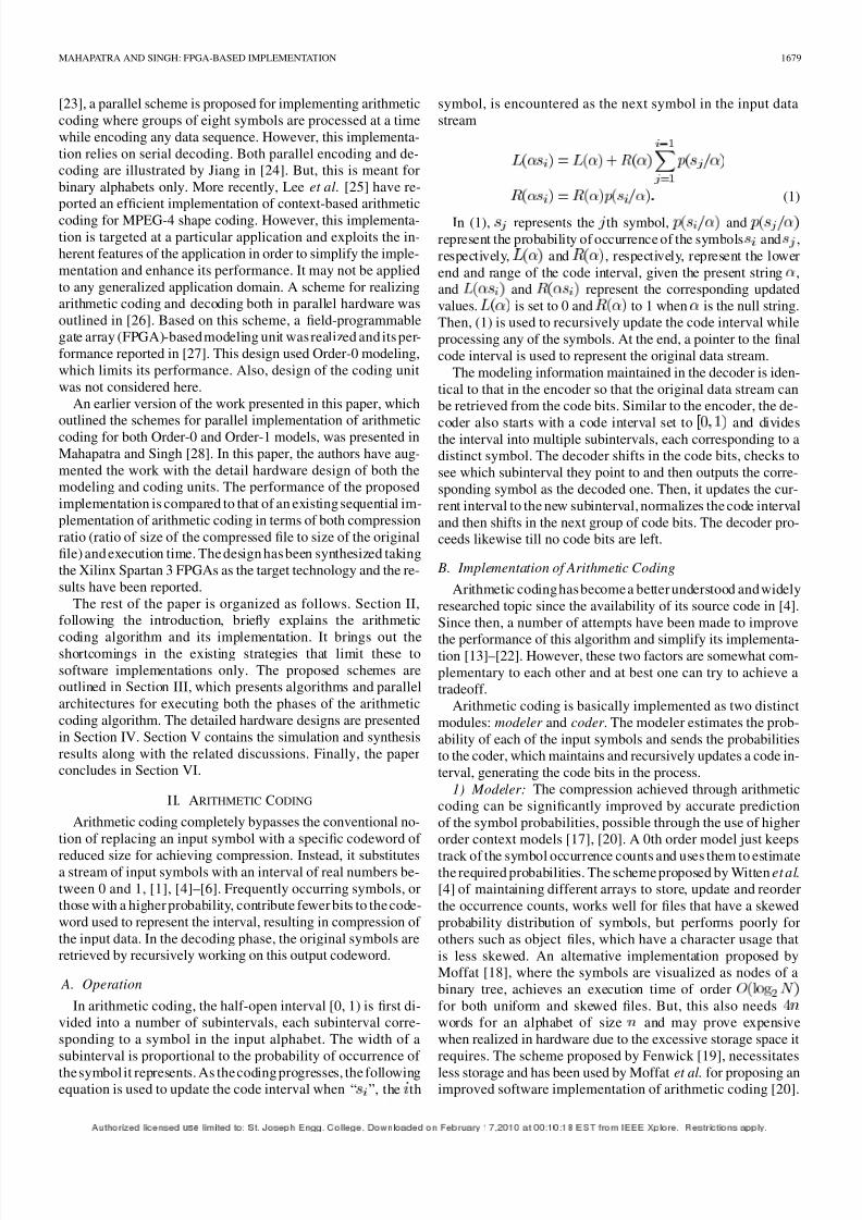
Fig. 2. Algorithm followed by Order-0 modeling unit.
bit of the symbol is zero. This achieves the necessary adaptation
in the code space at node , which has 0 as the lower end
point, as the intermediate point, and as the upperend point. The algorithm followed by Order-0 modeling unit is
shown in Fig. 2.
2) Order-1 Modeling: Similar to Order-0 modeling, in
Order-1 modeling also, the modeling information is stored in
each of the intermediate nodes of a binary tree. However, for
an alphabet of symbols, the information is now stored at
each tree node as two -element linear arrays and ,
indexed by the symbols in the alphabet. For any tree node,
stores the count of “0”s and stores the total count of
“0”s and “1”s encountered by the node, after seeing the symbol
. The code space at node now has 0 as the lower end
point, as the intermediate point and as the
upper end point where represents the previous symbol. Thealgorithm followed by Order-1 modeling is shown in Fig. 3. In
8/6/2019 Arith Coding
http://slidepdf.com/reader/full/arith-coding 4/9
MAHAPATRA AND SINGH: FPGA-BASED IMPLEMENTATION 1681
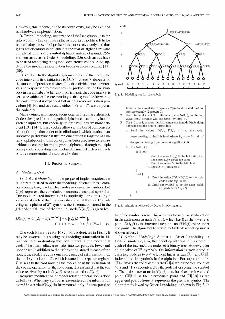
Fig. 3. Algorithm followed by Order-1 modeling unit.
Fig. 4. Parallel arithmetic encoder.
this algorithm, has the same interpretation as in algorithm of
Fig. 2.
3) Implementation: The modeler is realized as a linear array
of pipelined units, to (Fig. 4). For a 256-symbol al-
phabet, there are eight levels in the modeling tree. Each unit
in the modeler stores the modeling information for all the nodes
at the corresponding tree level, i.e., , stores the
modeling information for the nodes to .
B. Coding Unit
The coding unit consists of multiple binary coders, i.e.,to as shown in Fig. 4. The coder , receives
the intermediate point and top of the corresponding code interval
as modeling information, as well as the bit , from . It then
uses 0 as the lower end of the interval and encodes either the
lower or upper part of the interval depending on .
In the proposed scheme, the input symbols are routed through
each of the modeling units. As a symbol reaches ,
it reads the bit and works according to Algorithm 1 or 2. The
coder , upon receiving the modeling information and ,
generates the code bits and shifts them into an internal buffer.
The input data stream is compressed in blocks of a particular
size and the resulting output files corresponding to the different
levels are either stored as the compressed data or sent out as asequence of code bits properly delimited from each other.
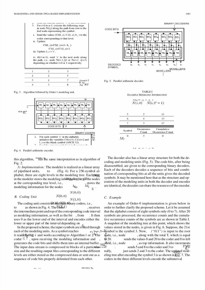
Fig. 5. Parallel arithmetic decoder.
TABLE IEXAMPLE MODELING INFORMATION
The decoder also has a linear array structure for both the de-
coding and modeling units (Fig. 5). The code bits, after being
disassembled, are given to the corresponding binary decoders.
Each of the decoders decodes a sequence of bits and combi-
nation of corresponding bits at all the units gives the decoded
symbols. It may be mentioned here that as the structure and op-
eration of the modeling units in both the decoder and encoder
are identical, the decoder can share the resources of the encoder.
C. Example
An example of Order-0 implementation is given below inorder to further clarify the proposed scheme. Let it be assumed
that the alphabet consist of eight symbols only (0 to 7). After 20
symbols are processed, the occurrence counts and the cumula-
tive occurrence counts of the symbols are as shown in Table I.
A snapshot of the modeling tree at this point, which shows the
values stored in the nodes, is given in Fig. 6. Suppose, the 21st
symbol is the symbol 3. Now, (“011”) is input to the root
node, i.e., node , along with the total T, which is equal
to 20. sends the values 8 and 20 to the coder and 8 to left
child, i.e., node , as top information. It also increments
. sends 5 and 8 to the coder and 3 to . Fi-
nally, just sends 2 and 3 to the coder. The updated mod-
eling tree after encoding the symbol 3 is as shown in Fig. 7. Thecoders in the three different levels encode the subinterval

8/6/2019 Arith Coding
http://slidepdf.com/reader/full/arith-coding 5/9
1682 IEEE TRANSACTIONS ON CIRCUITS AND SYSTEMS—I: REGULAR PAPERS, VOL. 54, NO. 8, AUGUST 2007
Fig. 6. Example modeling tree.
Fig. 7. Updated modeling tree.
Fig. 8. Functionality of M for Order–0 modeling.
in the interval , the subinterval in the interval
and the subinterval in the interval , respectively.
IV. DETAIL HARDWARE DESIGN
A. Order-0 Modeling Unit
The functionality of for Order-0 modeling is shown in
Fig. 8. As mentioned in Subsection III-A, needs to store
only the root node of the modeling tree. It uses a 16-bit registerNODE_DATA to store the modeling information. The other
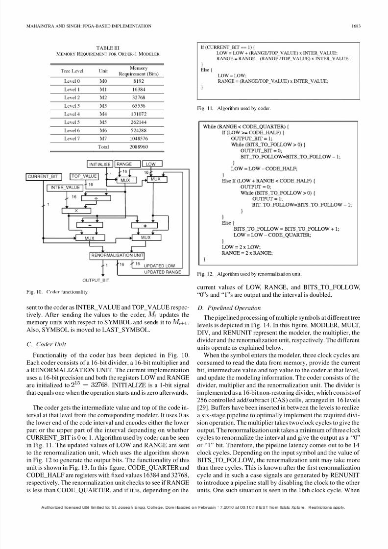
TABLE IIMEMORY REQUIREMENT FOR ORDER-0 MODELER
Fig. 9. Functionality of M
for Order-1 modeling.
nodes in the modeling unit differ only in terms of the amount of
storage space required as they have to store multiple tree nodes.
The memory requirements of the modeling units are given in
Table II. However, the functionalities of these units are identical
to each other. Each unit takes two values as input from
, i.e., SYMBOL and VALUE_FROM_TOP. It extracts
the corresponding bit of the symbol and sends it as CUR-
RENT_BIT to the coder together with VALUE_FROM_TOP
and NODE_DATA as TOP_VALUE and INTER_VALUE,
respectively. then computes the data to be sent to the next
unit and updates NODE_DATA.
B. Order-1 Modeling Unit Fig. 9 depicts the functionality of for Order-1 modeling.
The unit now stores the occurrence counts of 0’s and the total
count with respect to the different symbols for the root node. Ob-
viously, there is an increase in the memory requirement as com-
pared to the corresponding Order-0 modeling unit. Now,
has two memory units of 256*16 bits each and a register named
LAST_SYMBOL. Each of the other units, i.e., ,
stores the above modeling information for all the tree nodes at
the corresponding level. Hence, they differ only in the amount of
storage space needed. The memory requirements of the Order-1
modeling units are given in Table III. Each unit gets the
current symbol SYMBOL as input from and then using
LAST_SYMBOL as an index retrieves the intermediate and topvalues of the code interval from the memory units. These are
8/6/2019 Arith Coding
http://slidepdf.com/reader/full/arith-coding 6/9
MAHAPATRA AND SINGH: FPGA-BASED IMPLEMENTATION 1683
TABLE IIIMEMORY REQUIREMENT FOR ORDER-1 MODELER
Fig. 10. Coder functionality.
sent to the coder as INTER_VALUE and TOP_VALUE respec-
tively. After sending the values to the coder, updates the
memory units with respect to SYMBOL and sends it to .
Also, SYMBOL is moved to LAST_SYMBOL.
C. Coder Unit
Functionality of the coder has been depicted in Fig. 10.
Each coder consists of a 16-bit divider, a 16-bit multiplier and
a RENORMALIZATION UNIT. The current implementation
uses a 16-bit precision and both the registers LOW and RANGE
are initialized to . INITIALIZE is a 1-bit signalthat equals one when the operation starts and is zero afterwards.
The coder gets the intermediate value and top of the code in-
terval at that level from the corresponding modeler. It uses 0 as
the lower end of the code interval and encodes either the lower
part or the upper part of the interval depending on whether
CURRENT_BIT is 0 or 1. Algorithm used by coder can be seen
in Fig. 11. The updated values of LOW and RANGE are sent
to the renormalization unit, which uses the algorithm shown
in Fig. 12 to generate the output bits. The functionality of this
unit is shown in Fig. 13. In this figure, CODE_QUARTER and
CODE_HALF are registers with fixed values 16384 and 32768,
respectively. The renormalization unit checks to see if RANGEis less than CODE_QUARTER, and if it is, depending on the
Fig. 11. Algorithm used by coder.
Fig. 12. Algorithm used by renormalization unit.
current values of LOW, RANGE, and BITS_TO_FOLLOW,“0”s and “1”s are output and the interval is doubled.
D. Pipelined Operation
The pipelined processing of multiple symbols at different tree
levels is depicted in Fig. 14. In this figure, MODLER, MULT,
DIV, and RENUNIT represent the modeler, the multiplier, the
divider and the renormalization unit, respectively. The different
units operate as explained below.
When the symbol enters the modeler, three clock cycles are
consumed to read the data from memory, provide the current
bit, intermediate value and top value to the coder at that level,
and update the modeling information. The coder consists of the
divider, multiplier and the renormalization unit. The divider isimplemented as a 16-bit non-restoring divider, which consists of
256 controlled add/subtract (CAS) cells, arranged in 16 levels
[29]. Buffers have been inserted in between the levels to realize
a six-stage pipeline to optimally implement the required divi-
sion operation. The multiplier takes two clock cycles to give the
output. The renormalization unit takes a minimum of three clock
cycles to renormalize the interval and give the output as a “0”or “1” bit. Therefore, the pipeline latency comes out to be 14
clock cycles. Depending on the input symbol and the value of
BITS_TO_FOLLOW, the renormalization unit may take more
than three cycles. This is known after the first renormalization
cycle and in such a case signals are generated by RENUNIT
to introduce a pipeline stall by disabling the clock to the otherunits. One such situation is seen in the 16th clock cycle. When
8/6/2019 Arith Coding
http://slidepdf.com/reader/full/arith-coding 7/9
1684 IEEE TRANSACTIONS ON CIRCUITS AND SYSTEMS—I: REGULAR PAPERS, VOL. 54, NO. 8, AUGUST 2007
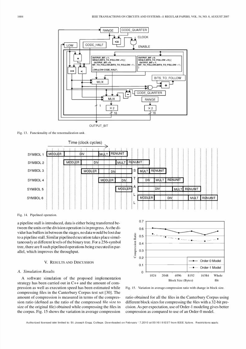
Fig. 13. Functionality of the renormalization unit.
Fig. 14. Pipelined operation.
a pipeline stall is introduced, data is either being transferred be-
tween the units or the division operation is in progress. As the di-
vider has buffers in between the stages, no data would be lost due
to a pipeline stall. Similar pipelined execution takes place simul-
taneously at different levels of the binary tree. For a 256-symbol
tree, there are 8 such pipelined operations being executed in par-
allel, which improves the throughput.
V. RESULTS AND DISCUSSION
A. Simulation Results
A software simulation of the proposed implementation
strategy has been carried out in C++ and the amount of com-
pression as well as execution speed has been estimated while
compressing files in the Canterbury Corpus test set [30]. The
amount of compression is measured in terms of the compres-
sion ratio (defined as the ratio of the compressed file size to
size of the original file) obtained while compressing the files inthe corpus. Fig. 15 shows the variation in average compression
Fig. 15. Variation in average compression ratio with change in block size.
ratio obtained for all the files in the Canterbury Corpus using
different block sizes for compressing the files with a 32-bit pre-
cision. As per expectation, use of Order-1 modeling gives bettercompression as compared to use of an Order-0 model.
8/6/2019 Arith Coding
http://slidepdf.com/reader/full/arith-coding 8/9
8/6/2019 Arith Coding
http://slidepdf.com/reader/full/arith-coding 9/9
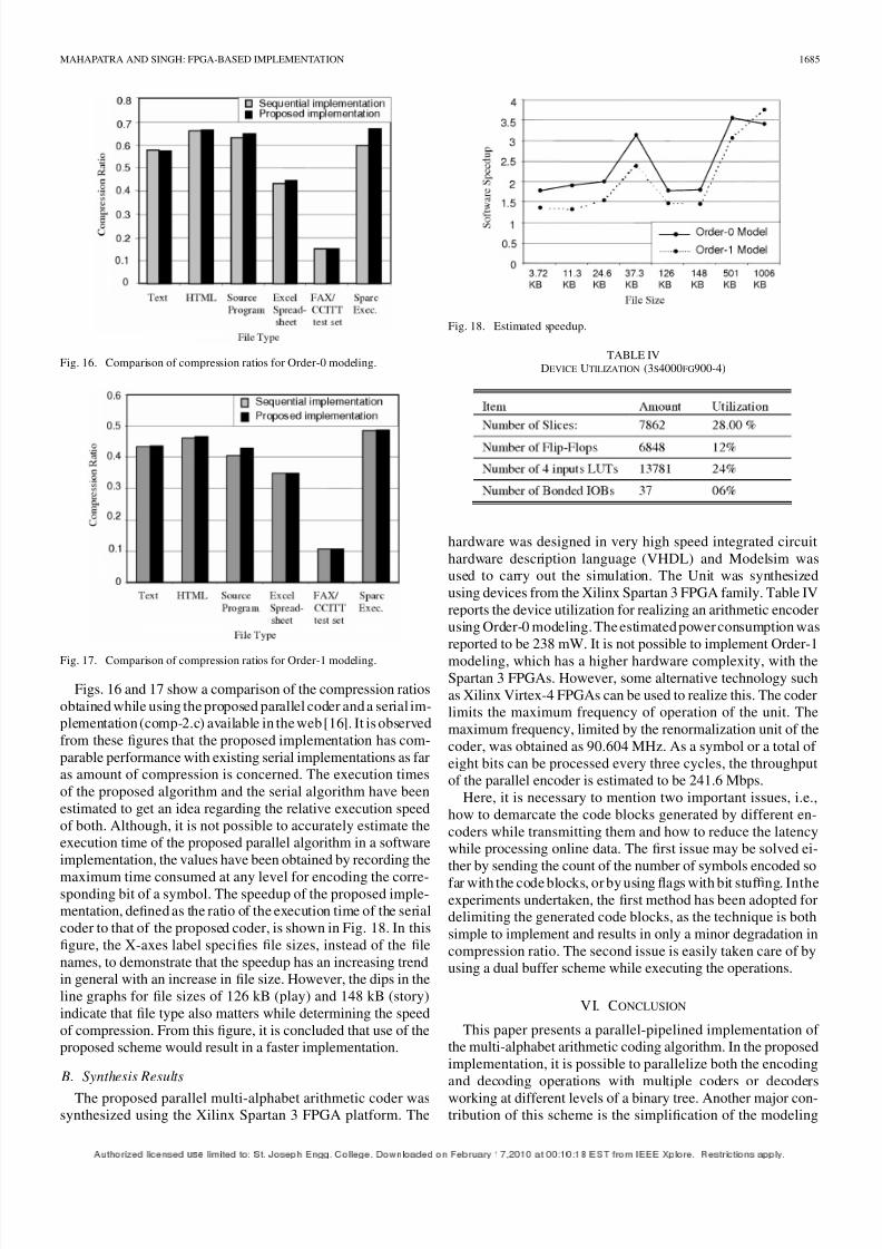
1686 IEEE TRANSACTIONS ON CIRCUITS AND SYSTEMS—I: REGULAR PAPERS, VOL. 54, NO. 8, AUGUST 2007
unit, which reduces the required hardware resources in addition
to reducing the encoding and decoding times.
Compression performance of the proposed implementation
has been compared with one of the existing serial implementa-
tions in terms of both compression ratio and execution time. It is
seen that the proposed implementation would result in a better
implementation as far as execution speed is concerned while
giving comparable compression ratios. The proposed scheme
also greatly simplifies the hardware realization of the different
modules.
REFERENCES
[1] T. Bell, J. Cleary, andI. Witten , Text Compression. EnglewoodCliffs,NJ: Prentice-Hall, 1990.
[2] J. Ziv and A. Lempel, “Compression of individual sequences viavariable rate coding,” IEEE Trans. Inf. Theory, vol. IT-24, no. 5, pp.530–536, Sep. 1978.
[3] D. A. Huffman, “A method for the construction of minimum redun-dancy codes,” in Proc. Inst. Radio Eng., 1952, vol. 40, pp. 1098–1101.
[4] I. H. Witten, R. M. Neal, and J. G. Cleary, “Arithmetic coding for datacompression,” Comm. ACM , vol. 30, no. 6, pp. 520–540, Jun. 1987.
[5] G. G. Langdon, “An introduction to arithmetic coding,” IBM J. Res. Dev., vol. 28, no. 2, pp. 135–149, Mar. 1984.
[6] P. G. Howard and J. S. Vitter, “Arithmetic coding for data compres-
sion,” Proc. IEEE , vol. 82, no. 6, pp. 857–865, Jun. 1994.[7] E. H. Yang and J. C. Keiffer, “Grammar-based codes: A new class of
universal source codes,” IEEE Trans. Inf. Theory, vol. 46, no. 5, pp.737–754, May 2000.
[8] J. C. Keiffer, E. H. Yang, G. Nelson, and P. Cosman, “Lossless com-pression via multilevelpattern matching,” IEEE Trans. Inf. Theory, vol.46, no. 7, pp. 1227–1245, Jul. 2000.
[9] E. H. Yang, A. Kaltchenko, and J. C. Keiffer, “Universal losslessdata compression with side informa-tion by using a conditional MPMgrammer transform,” IEEE Trans. Inf. Theory, vol. 47, no. 9, pp.2130–2150, Sep. 2001.
[10] S. Jones, “100 Mbits/s adaptive data compressor design using selec-tively shiftable content-addressablememory,” Proc. IEEE , vol.139,no.
4, pp. 498–502, Apr. 1992.[11] J.L. NunezandS. Jones, “Gbits/s lossless data compressionhardware,”
IEEE Trans. Very Large Scale Integr. (VLSI) Syst., vol. 11, no. 3, pp.499–510, Jun. 2003.
[12] M. Milward, J. L. Nunex, and D. Mulvaney, “Design and implemen-tation of a parallel high-speed data compression system,” IEEE Trans.
Parallel Distr. Syst., vol. 15, no. 6, pp. 481–490, Jun. 2004.[13] G. G. Langdon and J. Rissanen, “Compression of black-and-white im-
ages with arithmetic coding,” IEEE Trans. Commun., vol. COM-29, no.6, pp. 858–867, Jun. 1981.
[14] S. Kuang, J. Jou, and Y. Chen, “The design of an adaptive on-line bi-nary arithmetic coding chip,” IEEE Trans. Circuits Syst. I , Fundam.
Theory Appl., vol. 45, no. 7, pp. 693–706, Jul. 1998.[15] G. V. Cormack and Horspool, “Data compression using dynamic
Markov modeling,” Comp. J., vol. 30, no. 6, pp. 541–550, Dec. 1987.[16] M. Nelson, “Arithmetic coding + statistical modeling = data com-
pression, part 1-arithmetic coding,” Dr. Dobb’s J. Feb. 1991 [Online].
Available: http://dogma.net/markn/articles/arith/part1.htm[17] M. Nelson, “Arithmetic coding
+
statistical modeling=
data compres-sion, part 2-statistical modeling,” Dr. Dobb’s J. Feb. 1991 [Online].Available: http://dogma.net/markn/articles/arith/part2.htm
[18] A. Moffat, “Linear time adaptive arithmetic coding,” IEEE Trans. Inf.Theory, vol. 36, no. 2, pp. 401–406, Mar. 1990.
[19] P. M. Fenwick, “A newdata structurefor cumulative frequency tables,”Soft. Prac. Exp. 24, vol. 3, pp. 327–336, Mar. 1994.
[20] A. Moffat and I. H. Witten, “Arithmetic coding revisited,” ACM Trans.
Inf. Syst., vol. 16, no. 3, pp. 256–294, Jul. 1998.[21] M. Boo, J. D. Bruguera, and T. Yang, “A VLSI architecture for
arithmetic coding of multilevel images,” IEEE Trans. Circuits Syst. II,
Analog Digit. Signal Process., vol. 45, no. 1, pp. 163, 168, Jan. 1998.[22] R. Osorio and J. Bruguera, “New arithmetic coder/decoder architec-
tures based on pipelining,” in Proc. IEEE Int. Conf. Application-Spe-
cific Syst., Arch. Process., Jul. 1997, pp. 106–115.
[23] J. Jiang and S. Jones, “Parallel design of arithmetic coding,” Proc. IEE Comp. Digit. Tech., vol. 144, no. 6, pp. 327–333, Nov, 1994.[24] J. Jiang, “A novel parallel architecture for black and white image com-
pression,” Signal Process. Image Commun., vol. 8, pp. 465–474, 1996.[25] K.-B. Lee, J.-Y. Lin, and C.-W. Jen, “A multisymbol context-based
arithmetic coding architecture for MPEG-4 shapecoding,” IEEETrans.
Circuits Syst. Video Tech., vol. 15, no. 2, pp. 283–295, Feb. 2005.[26] S. Mahapatra, J. Nunez, C. Feregrino-Uribe, and S. Jones, “Parallel
implementation of a multi-alphabet arithmetic coding algorithm,” in IEE Colloquium on Data Compression: Methodsand Implementations,23rd ed. London, U.K.: IEE, Nov. 1999.
[27] R. Stefo, J. L. Nunez, C. Feregrino, S. Mahapatra, and S. Jones,
“FPGA-based modeling unit for high speed lossless arithmeticcoding,” in Proc. 11th Int. Conf. FPL2001, Belfast, Northern Ireland,Aug. 2001, pp. 643–647.
[28] S. Mahapatra and K. Singh, “A parallel scheme for implementing mul-tialphabet arithmetic coding in high-speed programmable hardware,”
in Proc. IEEE Int. Conf. ITCC-05, Las Vegas, NV, 2005, pp. 79–84.[29] A. Guyot, “Divider,” TIMA-CMP, Grenoble, France, Feb. 2004 [On-
line]. Available: http://tima-cmp.imag.fr/~guyot/Cours/Oparithm/eng-lish/Divise.htm
[30] R. Arnold and T. Bell, “A corpus for the evaluation of lossless com-pression algorithms,” in Proc. IEEE Data Compression Conf , Snow-bird, UT, 1997, pp. 201–210.
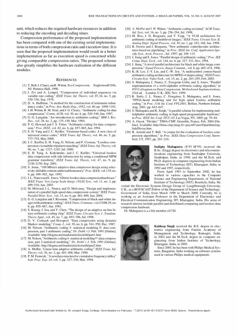
Sudipta Mahapatra (S’93–M’95) received theB.Sc. (Engg) degree in electronics and telecommu-nications engineering from Sambalpur University,Sambalpur, India, in 1990, and the M.Tech. andPh.D. degrees in computer engineering from IndianInstitute of Technology (IIT), Kharagpur, India, in1992 and 1997, respectively.
From April 1993 to September 2002, he has
worked in various capacities in the ComputerScience and Engineering Department, of NationalInstitute of Technology (NIT), Rourkela, India. He
visited the Electronic Systems Design Group of Loughborough University,U.K., as a BOYSCAST Fellow of the Department of Science and Technology,Government of India, from March 1999 to March 2000. Currently, he isworking as an Assistant Professor in the Department of Electronics andElectrical Communication Engineering, IIT, Kharagpur, India. His areas of research interest include parallel and distributed computing and lossless datacompression hardware.
Dr. Mahapatra is a a life member of CSI.
Kuldeep Singh received the B.E. degree in elec-tronics engineering from Finolex Academy of Management and Technology, Ratnagiri, India,in 2002 and the M.Tech. degree in computer en-gineering from Indian Institute of Technology,
Kharagpur, India, in 2005.Since 2005, he has been with Philips Medical Sys-
tems, Bangalore, India working on software systems
used in various Philips medical equipments.