ARIS EDGE LCD Shield User's Guide - Reloc€¦ · Document ARROW ARIS EDGE LCD Shield – User’s...
27
Document ARROW ARIS EDGE LCD Shield – User’s Guide 03/05/2018 Doc: R16P10DTUG02, Rev: 1.0 1 of 27 ARROW ARIS EDGE LCD Shield User’s Guide All information contained in these materials, including products and product specifications, represents information on the product at the time of publication and is subject to change by RELOC s.r.l. without notice.
Transcript of ARIS EDGE LCD Shield User's Guide - Reloc€¦ · Document ARROW ARIS EDGE LCD Shield – User’s...

Document
ARROW ARIS EDGE LCD Shield – User’s Guide 03/05/2018
Doc: R16P10DTUG02, Rev: 1.0 1 of 27
ARROW ARIS EDGE LCD Shield
User’s Guide
All information contained in these materials, including products and product specifications, represents
information on the product at the time of publication and is subject to change by RELOC s.r.l. without notice.
Document
ARROW ARIS EDGE LCD Shield – User’s Guide 03/05/2018
Doc: R16P10DTUG02, Rev: 1.0 2 of 27
Outline
1. Introduction .............................................................................................................................. 4
1.1. Description ........................................................................................................................ 4
1.2. Kit contents ....................................................................................................................... 4
2. System overview ...................................................................................................................... 5
2.1. Board main features .......................................................................................................... 5
2.2. Block diagram ................................................................................................................... 6
3. Getting started ......................................................................................................................... 7
3.1. ARIS EDGE S3 pre-programmed demo ............................................................................ 7
3.2. Creating and debugging a simple LCD project .................................................................. 9
3.2.1 Prerequisites ............................................................................................................ 9
3.2.2 ARIS EDGE S3 BSP ................................................................................................ 9
3.2.3 Creating and building an empty project .................................................................... 9
3.2.4 Creating a GUIX Studio project .............................................................................. 12
3.2.5 Configure the Synergy Configurator of the e2studio project.................................... 17
3.2.6 Copy the LCD driver into the e2studio project ........................................................ 20
3.2.7 Edit the gui thread source file ................................................................................. 20
3.2.8 Create a gui events handler file .............................................................................. 23
3.2.9 Board configuration and connection ....................................................................... 24
3.2.10 Program and debug S3 project ............................................................................... 24
4. Connectors and Layout .......................................................................................................... 25
4.1. Arduino connector ........................................................................................................... 27
Document
ARROW ARIS EDGE LCD Shield – User’s Guide 03/05/2018
Doc: R16P10DTUG02, Rev: 1.0 3 of 27
Revisions
REVISION DATE DESCRIPTION STATUS AUTHOR REVISER
0.1 02/05/2018 Document created draft C. Tagliaferri
1.0 03/05/2018 Document released release C. Tagliaferri L. Dal Bello
Disclaimer
All rights strictly reserved. Reproduction in any form is not permitted without written authorization from
RELOC s.r.l.
RELOC s.r.l.
HEADQUARTERS
Strada Langhirano, 264/3A 43124 – Parma (Italy)
Phone +39-0521-649116
www.reloc.it
Document
ARROW ARIS EDGE LCD Shield – User’s Guide 03/05/2018
Doc: R16P10DTUG02, Rev: 1.0 4 of 27
1. Introduction
1.1. Description
ARIS EDGE LCD shield, developed by RELOC for Arrow Electronics, is an ARIS EDGE S3 optional
board that extends the S3 potential with LCD and touch support.
1.2. Kit contents
The following items are included in the box:
• 1x ARIS EDGE LCD Shield
Document
ARROW ARIS EDGE LCD Shield – User’s Guide 03/05/2018
Doc: R16P10DTUG02, Rev: 1.0 5 of 27
2. System overview
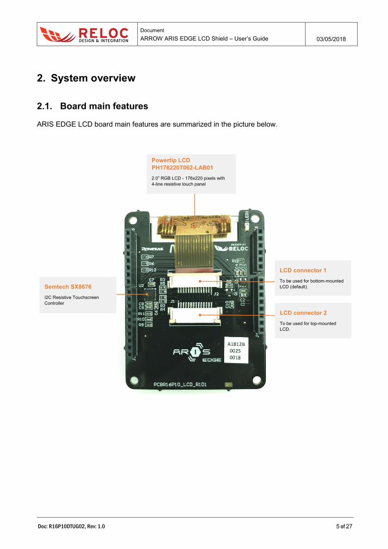
2.1. Board main features
ARIS EDGE LCD board main features are summarized in the picture below.
Powertip LCD
PH176220T062-LAB01
2.0” RGB LCD - 176x220 pixels with
4-line resistive touch panel
Semtech SX8676
I2C Resistive Touchscreen
Controller
LCD connector 1
To be used for bottom-mounted
LCD (default).
LCD connector 2
To be used for top-mounted
LCD.
Document
ARROW ARIS EDGE LCD Shield – User’s Guide 03/05/2018
Doc: R16P10DTUG02, Rev: 1.0 6 of 27
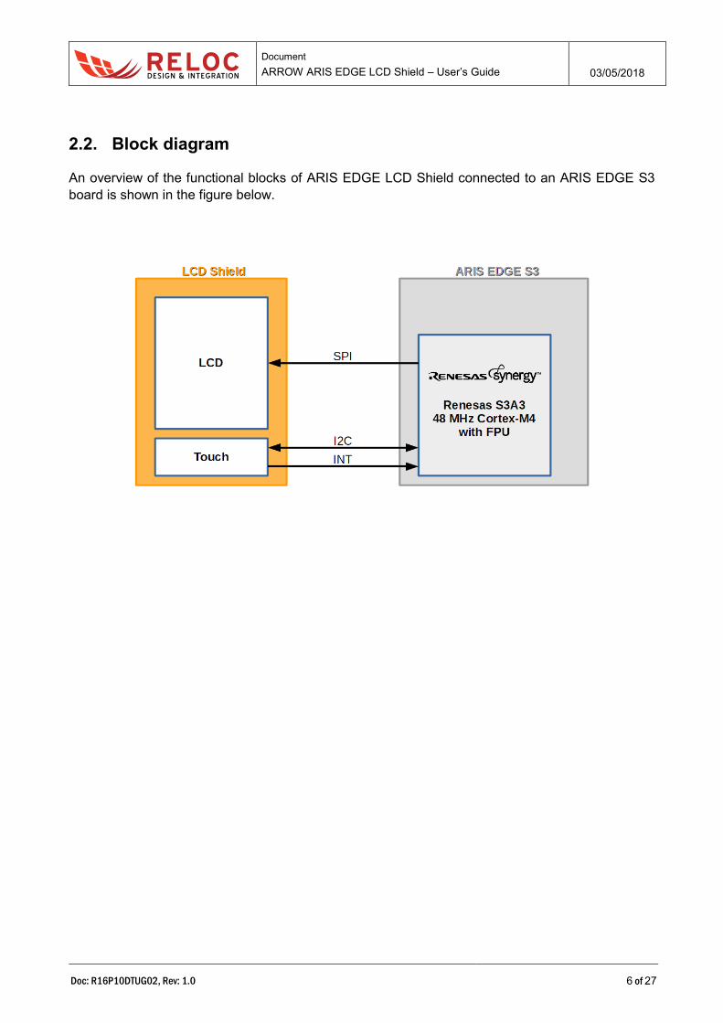
2.2. Block diagram
An overview of the functional blocks of ARIS EDGE LCD Shield connected to an ARIS EDGE S3
board is shown in the figure below.

Document
ARROW ARIS EDGE LCD Shield – User’s Guide 03/05/2018
Doc: R16P10DTUG02, Rev: 1.0 7 of 27
3. Getting started
3.1. ARIS EDGE S3 pre-programmed demo
The ARIS EDGE S3 board is pre-programmed with a demo application which continuously monitors
the on-board sensors and sends collected data on Bluetooth Low-Energy (BLE) network. Moreover,
if found, it drives the LCD shield.
To test the ARIS EDGE S3 and LCD Shield functionalities by means of the pre-programmed demo
application:
1. connect the ARIS EDGE LCD Shield under (bottom-mounted) the S3 Board;
2. power on the ARIS EDGE S3 board through either J2 or J5 USB connector.
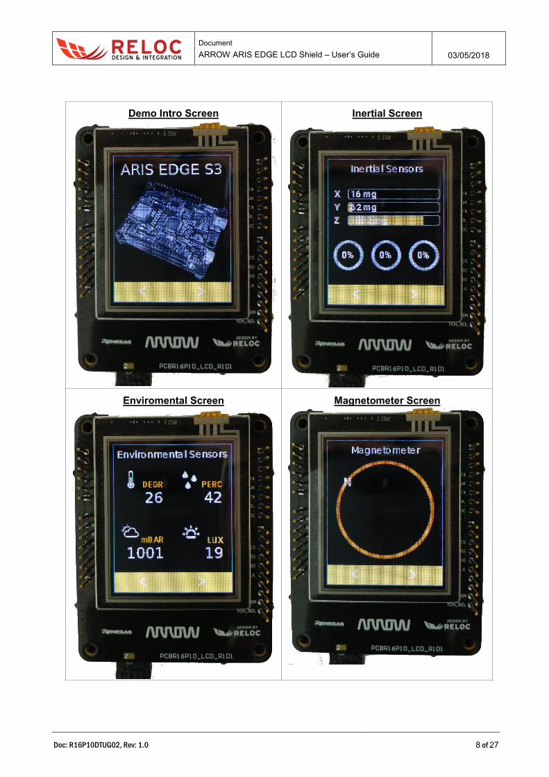
Different screens will be sequentially shown while sensors data will be continuously updated.
J5
J2
Document
ARROW ARIS EDGE LCD Shield – User’s Guide 03/05/2018
Doc: R16P10DTUG02, Rev: 1.0 8 of 27
Demo Intro Screen
Inertial Screen
Enviromental Screen
Magnetometer Screen

Document
ARROW ARIS EDGE LCD Shield – User’s Guide 03/05/2018
Doc: R16P10DTUG02, Rev: 1.0 9 of 27
3.2. Creating and debugging a simple LCD project
3.2.1 Prerequisites
The following development tools should be installed before trying to either create a project or use
any example based on ARIS board:
▪ e2 studio v6.2.0 or later release
▪ Synergy Software Package v1.4.0 or later release
Please refer to the Synergy Gallery website for more information and for obtaining the required
software.
3.2.2 ARIS EDGE S3 BSP
ARIS EDGE S3 Board Support Package (BSP) provides a default configuration for ARIS EDGE S3
board peripherals.
ARIS EDGE S3 BSP is available for download at the following link:
http://www.reloc.it/download/products/ARIS-EDGE-S3/reloc.aris_edge3.1.4.0.zip
In order to install it, please unzip the archive and copy the file “Reloc.Aris_Edge3.1.4.0.pack” in the
following directory:
%e2_studio_install_dir%\internal\projectgen\arm\Packs
where
%e2_studio_install_dir% is typically the folder “C:\Renesas\e2_studio\”
3.2.3 Creating and building an empty project
To create a Synergy project with the ARIS EDGE S3 board as a target, please follow the steps below
within e2 studio:
▪ Select File → New → Synergy C/C++ Project in the e2 studio main menu
▪ Select the template for a Renesas Synergy C Executable Project and press Next>
▪ Assign a new project name and select GCC ARM Embedded toolchain
A license file is required for using Synergy platform; an evaluation license is provided with SSP in
the following directory:
%e2_studio_install_dir%\internal\projectgen\arm\Licenses
Please refer to Synergy Gallery website for additional information about obtaining development and
production licenses.

Document
ARROW ARIS EDGE LCD Shield – User’s Guide 03/05/2018
Doc: R16P10DTUG02, Rev: 1.0 10 of 27
▪ Select the “aris_edge3” board and verify the other parameters accordingly to the picture
below
Document
ARROW ARIS EDGE LCD Shield – User’s Guide 03/05/2018
Doc: R16P10DTUG02, Rev: 1.0 11 of 27
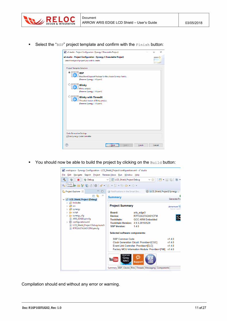
▪ Select the “BSP” project template and confirm with the Finish button:
▪ You should now be able to build the project by clicking on the Build button:
Compilation should end without any error or warning.

Document
ARROW ARIS EDGE LCD Shield – User’s Guide 03/05/2018
Doc: R16P10DTUG02, Rev: 1.0 12 of 27
3.2.4 Creating a GUIX Studio project
GUIX Studio is an Express Logic application used to create the GUI for a synergy project.
Start a new project using the Create New Project… button in the start up screen.
Assign the name LCD_Shield_project to the GUIX project and save it in a subfolder called guix
of the e2studio project.
In the next screen make sure to select the following settings:
▪ Target CPU: Renesas Synergy
▪ Toolchain: GNU
▪ Advanced Settings

Document
ARROW ARIS EDGE LCD Shield – User’s Guide 03/05/2018
Doc: R16P10DTUG02, Rev: 1.0 13 of 27
o Enable 2D Drawing Engine: NOT selected
o Runtime Image Decoder – JPEG: None
o Runtime Image Decoder – PNG: None
▪ Display Configuration
o x resolution: 176 pixels
o y resolution: 220 pixels
o 8 bpp
o Allocate canvas memory: not checked
Save the configuration and the initial screen will be shown:

Document
ARROW ARIS EDGE LCD Shield – User’s Guide 03/05/2018
Doc: R16P10DTUG02, Rev: 1.0 14 of 27
Add a new window to the display_1
and name it main_screen. Set the window’s property as indicated in the next image.

Document
ARROW ARIS EDGE LCD Shield – User’s Guide 03/05/2018
Doc: R16P10DTUG02, Rev: 1.0 15 of 27
Additionally, we need to name the event function that will be called when this window requires
actions, for example some buttons are pressed or the window gain/loss the focus. Set the property
Event Function to MainScreenEvents.
Now we can start to add some GUI elements, for example a Text Button.
Document
ARROW ARIS EDGE LCD Shield – User’s Guide 03/05/2018
Doc: R16P10DTUG02, Rev: 1.0 16 of 27
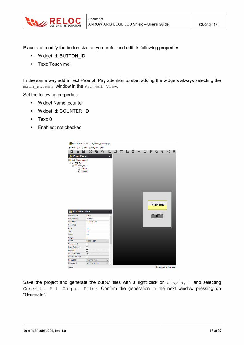
Place and modify the button size as you prefer and edit its following properties:
▪ Widget Id: BUTTON_ID
▪ Text: Touch me!
In the same way add a Text Prompt. Pay attention to start adding the widgets always selecting the
main_screen window in the Project View.
Set the following properties:
▪ Widget Name: counter
▪ Widget Id: COUNTER_ID
▪ Text: 0
▪ Enabled: not checked
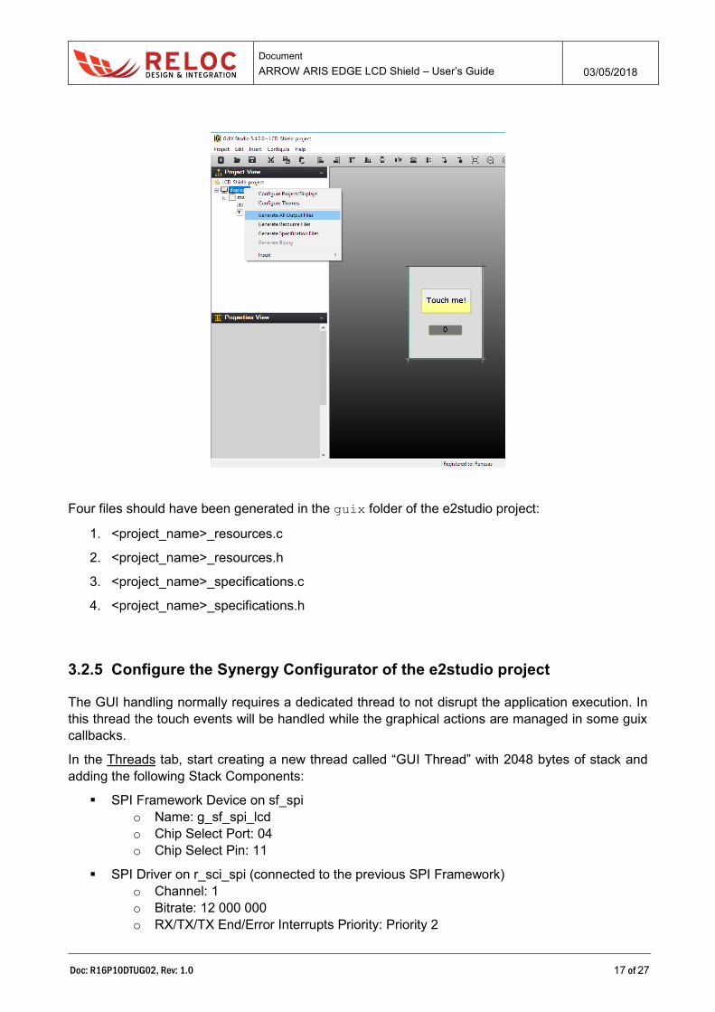
Save the project and generate the output files with a right click on display_1 and selecting
Generate All Output Files. Confirm the generation in the next window pressing on
“Generate”.
Document
ARROW ARIS EDGE LCD Shield – User’s Guide 03/05/2018
Doc: R16P10DTUG02, Rev: 1.0 17 of 27
Four files should have been generated in the guix folder of the e2studio project:
1. <project_name>_resources.c
2. <project_name>_resources.h
3. <project_name>_specifications.c
4. <project_name>_specifications.h
3.2.5 Configure the Synergy Configurator of the e2studio project
The GUI handling normally requires a dedicated thread to not disrupt the application execution. In
this thread the touch events will be handled while the graphical actions are managed in some guix
callbacks.
In the Threads tab, start creating a new thread called “GUI Thread” with 2048 bytes of stack and
adding the following Stack Components:
▪ SPI Framework Device on sf_spi
o Name: g_sf_spi_lcd
o Chip Select Port: 04
o Chip Select Pin: 11
▪ SPI Driver on r_sci_spi (connected to the previous SPI Framework)
o Channel: 1
o Bitrate: 12 000 000
o RX/TX/TX End/Error Interrupts Priority: Priority 2

Document
ARROW ARIS EDGE LCD Shield – User’s Guide 03/05/2018
Doc: R16P10DTUG02, Rev: 1.0 18 of 27
o Remove the DTC Drivers
▪ Timer Driver on r_gpt
o Name: g_timer_gui_bk
o Channel: 8
o Mode: PWM
o Period Value: 10
o Period Unit: Milliseconds
o Duty Cycle Value: 95
o Duty Cycle Unit: Unit Percent
o Auto Start: True
o GTIOCB Output Enable: True
o GTIOCB Stop Level: Pin Level High
▪ Touch Panel Framework on sf_touch_panel_i2c
o Hsize Pixels: 176
o Vsize Pixels: 220
o Reset Pin: IOPORT_PORT_01_PIN_05
▪ External IRQ Driver on r_icu (connected to the previous Touch Panel Framework, under the
External IRQ Framework)
o Channel: 1
o Trigger: Falling
▪ I2C Master Driver on r_riic (connected to the previous Touch Panel Framework)
o Channel: 1
o Rate: Fast-mode
o Slave Address: 0x48
▪ Touch Panel Driver on touch_panel_sx8654 (connected to the previous Touch Panel
Framework)
▪ Messaging Framework on sf_message
o Name: g_sf_message
The GUI Thread Stacks window should now appear like in the following image
Document
ARROW ARIS EDGE LCD Shield – User’s Guide 03/05/2018
Doc: R16P10DTUG02, Rev: 1.0 19 of 27
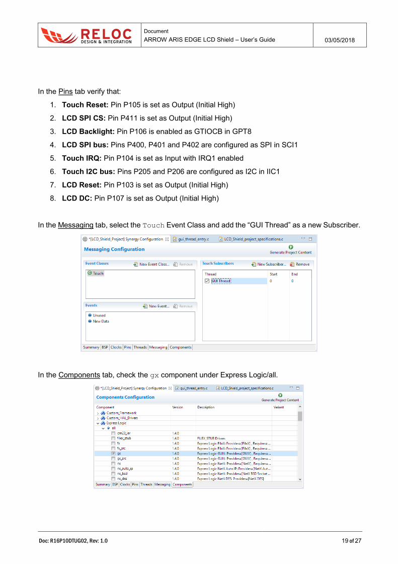
In the Pins tab verify that:
1. Touch Reset: Pin P105 is set as Output (Initial High)
2. LCD SPI CS: Pin P411 is set as Output (Initial High)
3. LCD Backlight: Pin P106 is enabled as GTIOCB in GPT8
4. LCD SPI bus: Pins P400, P401 and P402 are configured as SPI in SCI1
5. Touch IRQ: Pin P104 is set as Input with IRQ1 enabled
6. Touch I2C bus: Pins P205 and P206 are configured as I2C in IIC1
7. LCD Reset: Pin P103 is set as Output (Initial High)
8. LCD DC: Pin P107 is set as Output (Initial High)
In the Messaging tab, select the Touch Event Class and add the “GUI Thread” as a new Subscriber.
In the Components tab, check the gx component under Express Logic/all.

Document
ARROW ARIS EDGE LCD Shield – User’s Guide 03/05/2018
Doc: R16P10DTUG02, Rev: 1.0 20 of 27
3.2.6 Copy the LCD driver into the e2studio project
Copy the files:
▪ gx_on_ili9225_8bpp.c
▪ gx_on_ili9225_8bpp.h
▪ sf_ili9225.c
▪ sf_ili9225.h
into the src folder of the project.
3.2.7 Edit the gui thread source file
In this file the whole system will be initialized starting from touch, LCD and backlight configurations.
Lastly, the gui thread will receive the touch events re-routing them to the GUIX subsystem.
Modify the gui_thread_entry.c file adding the following code:
▪ Include section #include "gui_thread.h" #include "sf_ili9225.h" #include "gx_on_ili9225_8bpp.h" #include "guix/LCD_Shield_project_specifications.h" #include "guix/LCD_Shield_project_resources.h"
▪ Macro definitions /* LCD configuration - It reverse display */ #define LCD_BOTTOM_MOUNTED #define LCD_BYTE_PER_PIXEL 2 #define LCD_X_SIZE 176 #define LCD_Y_SIZE 220 #define FRAME_BUFFER_SIZE (LCD_X_SIZE * LCD_Y_SIZE) /* 8BPP */ #define BACKLIGHT_LEVEL_PERCENT 80
#define ASSERT(a) if(!(a)) __BKPT(0);
▪ Private functions prototypes static void hmi_send_touch_message(sf_touch_panel_payload_t * p_payload);
▪ Private variables static sf_ili9225_ctrl_t ili9225_ctrl; static sf_ili9225_cfg_t ili9225_cfg = { .reset_pin = IOPORT_PORT_01_PIN_03, .cmd_pin = IOPORT_PORT_01_PIN_07, .spi = &g_sf_spi_lcd, .x_size = LCD_X_SIZE, .y_size = LCD_Y_SIZE, .byte_per_pixel = LCD_BYTE_PER_PIXEL, #ifdef LCD_BOTTOM_MOUNTED .rotation_angle = 180, #else .rotation_angle = 0, #endif
Document
ARROW ARIS EDGE LCD Shield – User’s Guide 03/05/2018
Doc: R16P10DTUG02, Rev: 1.0 21 of 27
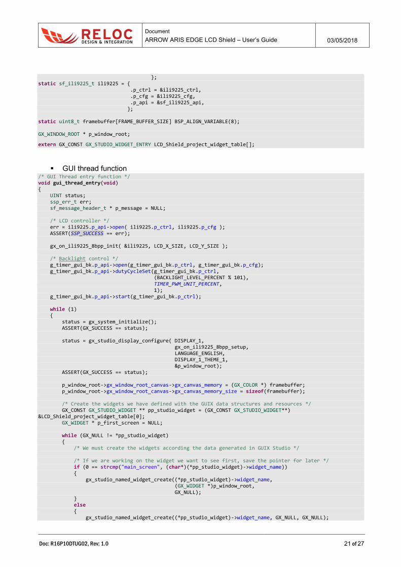
}; static sf_ili9225_t ili9225 = { .p_ctrl = &ili9225_ctrl, .p_cfg = &ili9225_cfg, .p_api = &sf_ili9225_api, }; static uint8_t framebuffer[FRAME_BUFFER_SIZE] BSP_ALIGN_VARIABLE(8); GX_WINDOW_ROOT * p_window_root;
extern GX_CONST GX_STUDIO_WIDGET_ENTRY LCD_Shield_project_widget_table[];
▪ GUI thread function /* GUI Thread entry function */ void gui_thread_entry(void) { UINT status; ssp_err_t err; sf_message_header_t * p_message = NULL; /* LCD controller */ err = ili9225.p_api->open( ili9225.p_ctrl, ili9225.p_cfg ); ASSERT(SSP_SUCCESS == err); gx_on_ili9225_8bpp_init( &ili9225, LCD_X_SIZE, LCD_Y_SIZE ); /* Backlight control */ g_timer_gui_bk.p_api->open(g_timer_gui_bk.p_ctrl, g_timer_gui_bk.p_cfg); g_timer_gui_bk.p_api->dutyCycleSet(g_timer_gui_bk.p_ctrl, (BACKLIGHT_LEVEL_PERCENT % 101), TIMER_PWM_UNIT_PERCENT, 1); g_timer_gui_bk.p_api->start(g_timer_gui_bk.p_ctrl); while (1) { status = gx_system_initialize(); ASSERT(GX_SUCCESS == status); status = gx_studio_display_configure( DISPLAY_1, gx_on_ili9225_8bpp_setup, LANGUAGE_ENGLISH, DISPLAY_1_THEME_1, &p_window_root); ASSERT(GX_SUCCESS == status); p_window_root->gx_window_root_canvas->gx_canvas_memory = (GX_COLOR *) framebuffer; p_window_root->gx_window_root_canvas->gx_canvas_memory_size = sizeof(framebuffer); /* Create the widgets we have defined with the GUIX data structures and resources */ GX_CONST GX_STUDIO_WIDGET ** pp_studio_widget = (GX_CONST GX_STUDIO_WIDGET**) &LCD_Shield_project_widget_table[0]; GX_WIDGET * p_first_screen = NULL; while (GX_NULL != *pp_studio_widget) { /* We must create the widgets according the data generated in GUIX Studio */ /* If we are working on the widget we want to see first, save the pointer for later */ if (0 == strcmp("main_screen", (char*)(*pp_studio_widget)->widget_name)) { gx_studio_named_widget_create((*pp_studio_widget)->widget_name, (GX_WIDGET *)p_window_root, GX_NULL); } else { gx_studio_named_widget_create((*pp_studio_widget)->widget_name, GX_NULL, GX_NULL);
Document
ARROW ARIS EDGE LCD Shield – User’s Guide 03/05/2018
Doc: R16P10DTUG02, Rev: 1.0 22 of 27
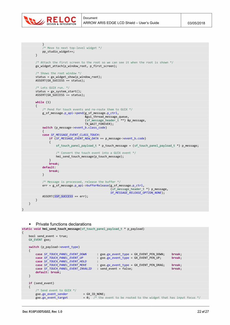
} /* Move to next top-level widget */ pp_studio_widget++; } /* Attach the first screen to the root so we can see it when the root is shown */ gx_widget_attach(p_window_root, p_first_screen); /* Shows the root window */ status = gx_widget_show(p_window_root); ASSERT(GX_SUCCESS == status); /* Lets GUIX run. */ status = gx_system_start(); ASSERT(GX_SUCCESS == status); while (1) { /* Pend for touch events and re-route them to GUIX */ g_sf_message.p_api->pend(g_sf_message.p_ctrl, &gui_thread_message_queue, (sf_message_header_t **) &p_message, TX_WAIT_FOREVER); switch (p_message->event_b.class_code) { case SF_MESSAGE_EVENT_CLASS_TOUCH: if (SF_MESSAGE_EVENT_NEW_DATA == p_message->event_b.code) { sf_touch_panel_payload_t * p_touch_message = (sf_touch_panel_payload_t *) p_message; /* Convert the touch event into a GUIX event */ hmi_send_touch_message(p_touch_message); } break; default: break; } /* Message is processed, release the buffer */ err = g_sf_message.p_api->bufferRelease(g_sf_message.p_ctrl, (sf_message_header_t *) p_message, SF_MESSAGE_RELEASE_OPTION_NONE); ASSERT(SSP_SUCCESS == err); } }
}
▪ Private functions declarations static void hmi_send_touch_message(sf_touch_panel_payload_t * p_payload) { bool send_event = true; GX_EVENT gxe; switch (p_payload->event_type) { case SF_TOUCH_PANEL_EVENT_DOWN : gxe.gx_event_type = GX_EVENT_PEN_DOWN; break; case SF_TOUCH_PANEL_EVENT_UP : gxe.gx_event_type = GX_EVENT_PEN_UP; break; case SF_TOUCH_PANEL_EVENT_HOLD : case SF_TOUCH_PANEL_EVENT_MOVE : gxe.gx_event_type = GX_EVENT_PEN_DRAG; break; case SF_TOUCH_PANEL_EVENT_INVALID : send_event = false; break; default: break; } if (send_event) { /* Send event to GUIX */ gxe.gx_event_sender = GX_ID_NONE; gxe.gx_event_target = 0; /* the event to be routed to the widget that has input focus */
Document
ARROW ARIS EDGE LCD Shield – User’s Guide 03/05/2018
Doc: R16P10DTUG02, Rev: 1.0 23 of 27
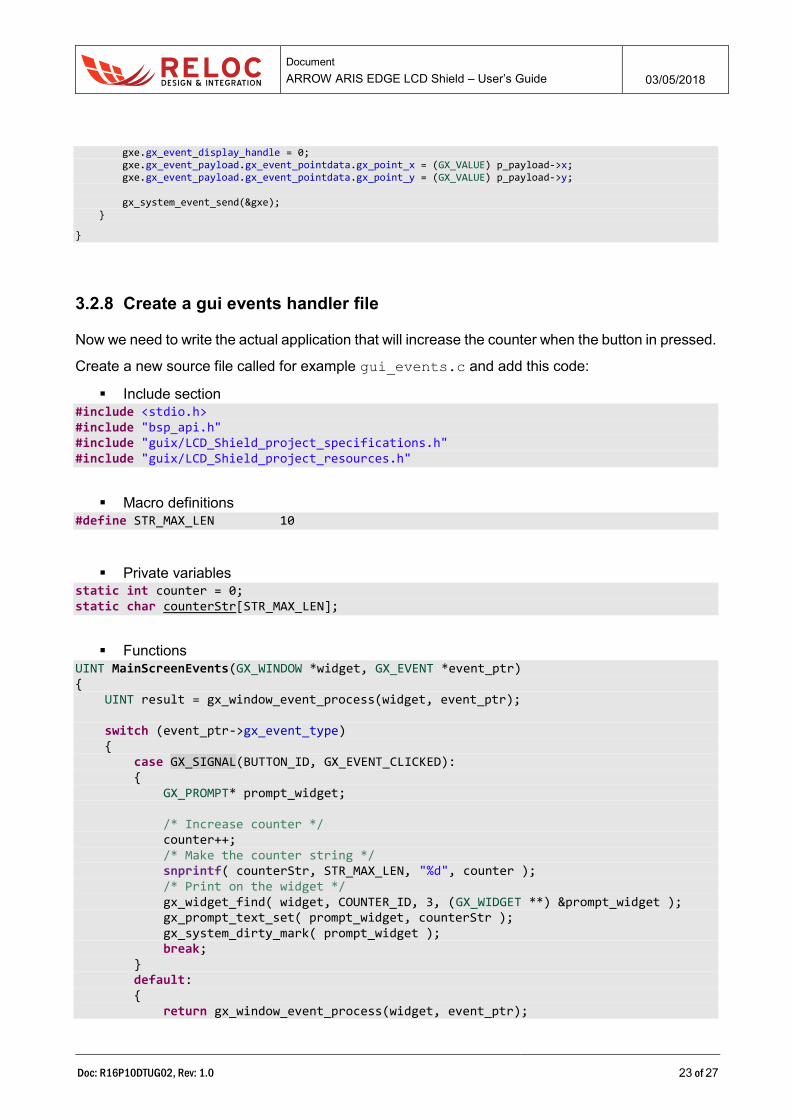
gxe.gx_event_display_handle = 0; gxe.gx_event_payload.gx_event_pointdata.gx_point_x = (GX_VALUE) p_payload->x; gxe.gx_event_payload.gx_event_pointdata.gx_point_y = (GX_VALUE) p_payload->y; gx_system_event_send(&gxe); }
}
3.2.8 Create a gui events handler file
Now we need to write the actual application that will increase the counter when the button in pressed.
Create a new source file called for example gui_events.c and add this code:
▪ Include section #include <stdio.h> #include "bsp_api.h" #include "guix/LCD_Shield_project_specifications.h" #include "guix/LCD_Shield_project_resources.h"
▪ Macro definitions #define STR_MAX_LEN 10
▪ Private variables static int counter = 0; static char counterStr[STR_MAX_LEN];
▪ Functions UINT MainScreenEvents(GX_WINDOW *widget, GX_EVENT *event_ptr) { UINT result = gx_window_event_process(widget, event_ptr); switch (event_ptr->gx_event_type) { case GX_SIGNAL(BUTTON_ID, GX_EVENT_CLICKED): { GX_PROMPT* prompt_widget; /* Increase counter */ counter++; /* Make the counter string */ snprintf( counterStr, STR_MAX_LEN, "%d", counter ); /* Print on the widget */ gx_widget_find( widget, COUNTER_ID, 3, (GX_WIDGET **) &prompt_widget ); gx_prompt_text_set( prompt_widget, counterStr ); gx_system_dirty_mark( prompt_widget ); break; } default: { return gx_window_event_process(widget, event_ptr);
Document
ARROW ARIS EDGE LCD Shield – User’s Guide 03/05/2018
Doc: R16P10DTUG02, Rev: 1.0 24 of 27
} } return result; }
3.2.9 Board configuration and connection
Connect the ARIS EDGE S3 board to your PC through the mini-USB port - J5: this connection
provides board with power supply and represents the interface for project flashing and debugging
via on-board J-Link programmer.
Ensure that J15 jumper is open, i.e. the on-board J-Link debugger is connect to the S3 MCU.
Jumpers P1, P2 and P3 (populated in the default configuration) route power to the Synergy MCU
and to peripheral components. P1 can also be used to measure the current consumption of the S3
device.
Please refer to following chapters for additional information about the board power supply
distribution.
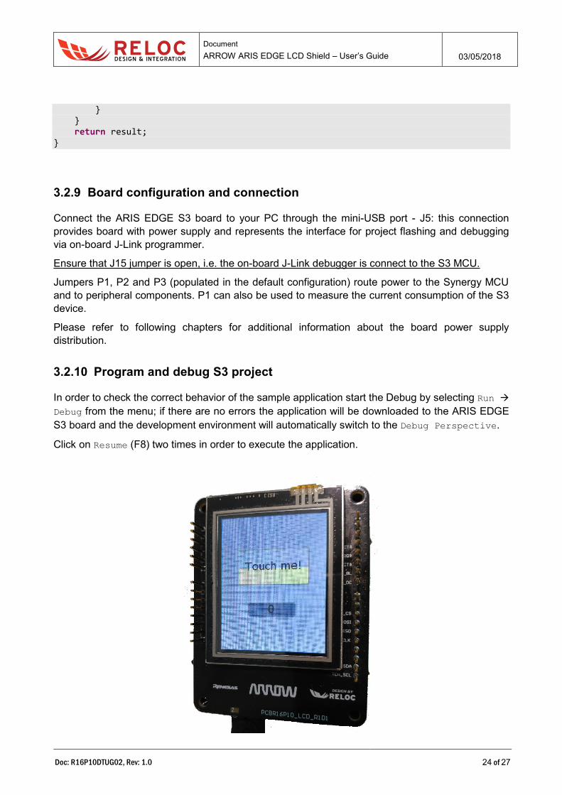
3.2.10 Program and debug S3 project
In order to check the correct behavior of the sample application start the Debug by selecting Run →
Debug from the menu; if there are no errors the application will be downloaded to the ARIS EDGE
S3 board and the development environment will automatically switch to the Debug Perspective.
Click on Resume (F8) two times in order to execute the application.
Document
ARROW ARIS EDGE LCD Shield – User’s Guide 03/05/2018
Doc: R16P10DTUG02, Rev: 1.0 25 of 27
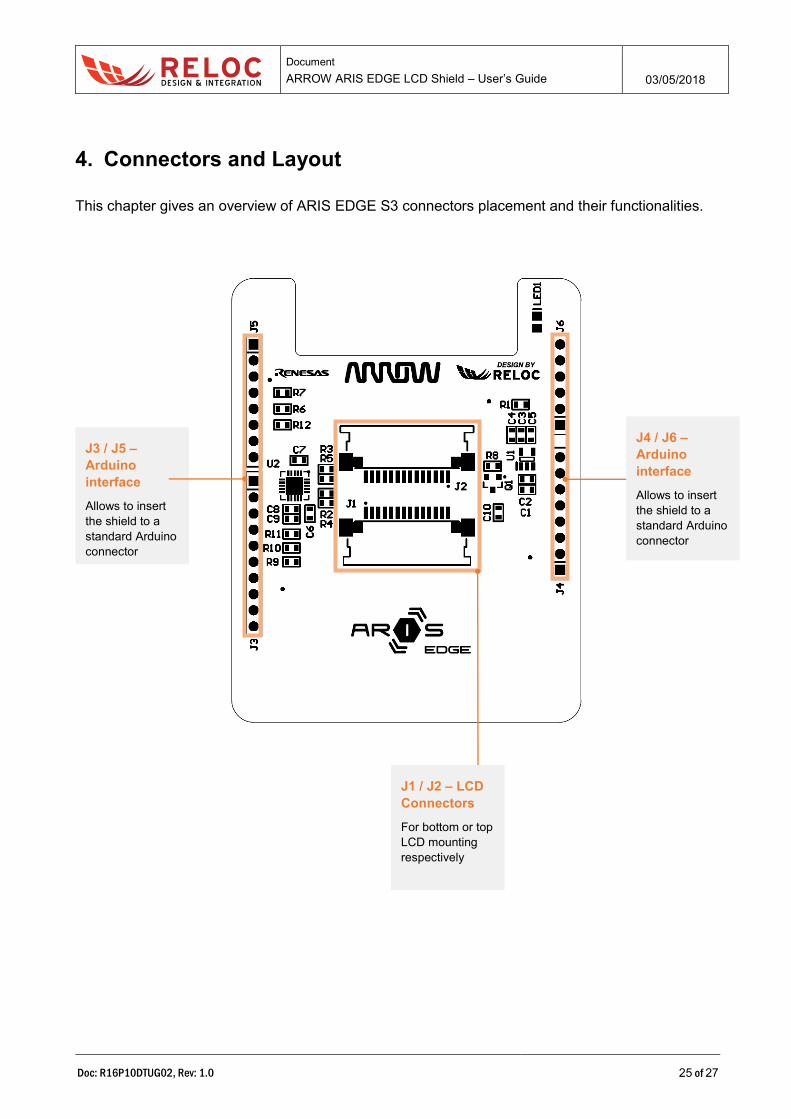
4. Connectors and Layout
This chapter gives an overview of ARIS EDGE S3 connectors placement and their functionalities.
J4 / J6 –
Arduino
interface
Allows to insert
the shield to a
standard Arduino
connector
J3 / J5 –
Arduino
interface
Allows to insert
the shield to a
standard Arduino
connector
J1 / J2 – LCD
Connectors
For bottom or top
LCD mounting
respectively
Document
ARROW ARIS EDGE LCD Shield – User’s Guide 03/05/2018
Doc: R16P10DTUG02, Rev: 1.0 26 of 27
Document
ARROW ARIS EDGE LCD Shield – User’s Guide 03/05/2018
Doc: R16P10DTUG02, Rev: 1.0 27 of 27
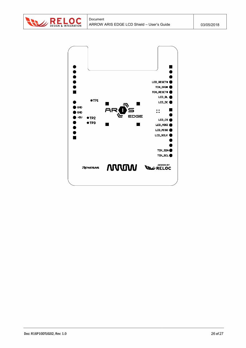
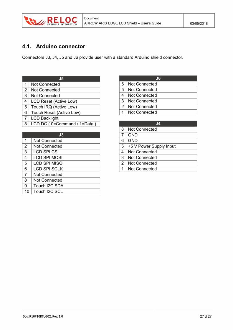
4.1. Arduino connector
Connectors J3, J4, J5 and J6 provide user with a standard Arduino shield connector.
J5
1 Not Connected
2 Not Connected
3 Not Connected
4 LCD Reset (Active Low)
5 Touch IRQ (Active Low)
6 Touch Reset (Active Low)
7 LCD Backlight
8 LCD DC ( 0=Command / 1=Data )
J6
6 Not Connected
5 Not Connected
4 Not Connected
3 Not Connected
2 Not Connected
1 Not Connected
J4
8 Not Connected
7 GND
6 GND
5 +5 V Power Supply Input
4 Not Connected
3 Not Connected
2 Not Connected
1 Not Connected
J3
1 Not Connected
2 Not Connected
3 LCD SPI CS
4 LCD SPI MOSI
5 LCD SPI MISO
6 LCD SPI SCLK
7 Not Connected
8 Not Connected
9 Touch I2C SDA
10 Touch I2C SCL