
ARINC 600 SERIES - FC Lane · ARINC 600 Series backshells for a global offer solution. Please see...
48
ARINC 600 SERIES Rack & Panel Rectangular Connectors High Density and Modularity
Transcript of ARINC 600 SERIES - FC Lane · ARINC 600 Series backshells for a global offer solution. Please see...

AR
INC
60
0 S
ER
IES
Rack & Panel Rectangular ConnectorsHigh Density and Modularity


3
ARINC 600 Series
Typical applications .......................................... 6Features & Benefi ts .......................................... 7A wide product range ...................................... 8Worldwide sales network ................................. 8 How to build an ARINC 600 ............................. 9A global offer with SUNBANK ......................... 9 Insert layouts .................................................... 10Shell types and cavities overview ..................... 11 Insert layouts matrix ......................................... 12Contacts overview ............................................ 13
Overview
Technical features ............................................. 16Ordering information ....................................... 17Sealing level ..................................................... 17Plating & Grounding ........................................ 18Dimensions ....................................................... 19 Contacts release & Mounting style .................. 22
Product Series
Presentation
Crimp contacts ................................................. 30PC tail contacts ................................................. 33Wire wrap contacts ........................................... 34Quadrax contacts ............................................. 35ELIO® fi ber optic contacts ................................ 35Tooling .............................................................. 36Accessories and Backshells .............................. 38
Common Section
Custom products .............................................. 44 microComp® Series .......................................... 44Nafi 1 & 2 Series ............................................... 45D-Subminiature Series ...................................... 45Box mount interconnect solutions .................... 46
Range Extension
Inserts arrangement code ................................ 23Polarization code .............................................. 24 Packaging code ................................................ 25 Cost effective version ....................................... 26
Contents
BUILD THE CONNECTOR THAT MATCHES EXACTLY YOUR REQUIREMENTS
Modular• Wide range of insulators compliant with all type of technology from signal to power, high speed and fiber optic
Confi gurable• RoHS Surtec, nickel, alodine • Multiple fi xing type• EMI RFI shielding solution • Grounding options• Up to 100A power capabilty • Filtering solutions
High Density• Up to 800 #22 signal contacts• Up to 56 #8 Quadrax or ELIO® contacts
Rackable• Blind mate, clearance device for better rackability• Low insertion force
Easy Repairable• Front and rear release removable contacts for easy integration with Printed Card Board, fl ex circuit or cabled harnesses.
C O M P L I A N T

AR
INC
60
0 S
ER
IES
© 2017 SOURIAU - SOURIAU is a registered trademark

OverviewARINC 600 Series
Typical applications ................................................................................................ 6
Features & Benefi ts ................................................................................................ 7
A wide product range ............................................................................................. 8
Worldwide sales network ........................................................................................ 8
How to build an ARINC 600 .................................................................................... 9
A global offer with SUNBANK ................................................................................ 9
Insert layouts ........................................................................................................... 10
Shell types and cavity overview .............................................................................. 11
Insert layouts matrix, Contact release/sealing compatibility ................................... 12
Contacts overview .................................................................................................. 13

6
ARINC 600 Series | Overview
Engine Management
© Ic
hola
kov
/ Fo
tolia
Typical applications
Cockpit Display Units
Cabin: IFE & Air Conditioning Avionic Bay/Data Acquisition
Cou
rtes
y of
NO
RD-M
ICRO
© A
vata
r_02
3 /
Shut
ters
tock
© S
tud
ioSm
art
/ Sh
utte
rsto
ck
Landing Gear Management
© L
ee Y
iu T
ung
/ S
hutt
erst
ock
© A
lexa
ndr
Miti
uc /
Fot
olia
We ConnectTHE HEART
of your
System
Cockpit
Avionic Bay

7
ARINC 600 Series | Overview
Features & Benefi ts
TIMESAVING
MAKE IT YOURS
WEIGHT & SPACE SAVING
COSTSAVING
Rackable Solution & Easy MaintenanceBlind mate, clearance device for better rackability.Low insertion force.Front and rear release removable contacts.
Confi gurable SolutionCost effective option with no removable contacts.Contacts number to match your need.
High Density SolutionUp to 800 #22 signal contacts.Up to 56 #8 quadrax contacts.
Modular Solution A wide range of insulators compliant with all types of technologies: signal, power, high speed and fi ber optic.Compliant with PCB, fl ex circuit and harness implementation.

8
ARINC 600 Series | Overview
Worldwide sales network
SOURIAU is recognized as one of the top international manufacturers of connectors for harsh environment and is continuously strengthening its leading position through its solid structure as an international group. Today theSOURIAU group has a strong worldwide global presenceon 4 continents.
Our international presence is reinforced by franchised and value added distributors in many countries.
We also rely upon an extensive network of distributors and resellers worldwide. This coverage, together with a strong commitment towards service, ensures rapid responses tothe specifi c needs of our customers.
SOURIAU Operations & Sales Offi ces
Franchised & Value Added Distributors
3shell sizes,3 platings
ManyOptions
A FullContacts
Offer
Shells & LayoutsShell sizes 1, 2 and 3Equipment Receptacle and Rack PlugMore than 30 insertlayouts available
PlatingSurtec, Alodine and Nickel
High DensityUp to 800 signal contacts in the same shell
VersatilityCoax, Triax, Twinax and Power Contacts
High Speed DataQuadrax and Fiber Optic
Make it Yours!Sealed and Unsealed versionMultiple Polarizing positionsGrounding options
Cost Effective versionHarpooned contacts
A wide product range
shell sizes,3 l ti
A FullContacts
Off

9
ARINC 600 Series | Overview
How to build an ARINC 600
For a new project, gather all informations:
Sealing level & plating
Shell size
Shell type
Contact mounting & release
Mounting style
Inserts C & F
Contact type
Inserts A, B, D & E
Polarization code
Packaging code
= Your Connector!Match perfectly yourbox connection needs.
1
2
3
4
5
6
7
8
9
10
SOURIAU in partnership with SUNBANK can offer dedicated ARINC 600 Series backshells for a global offer solution. Please see pages 39 to 41 for available confi gurations.
Based in California since 1958, and with a fi rm presence inaerospace and military markets, SUNBANK is the world’ssecond-largest producer of accessories for electrical wiringharness connectors and conduits.
For more information about SUNBANK please visit ourwebsite: www.sunbankcorp.com
A global offer with SUNBANK

10
ARINC 600 Series | Overview
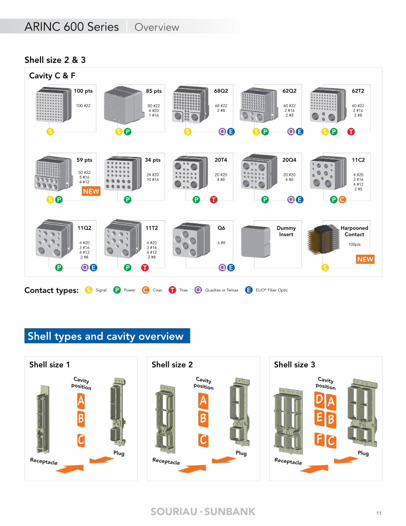
Contact types: CoaxPowerSignal Triax ELIO® Fiber OpticQuadrax or TwinaxPS T QC E
Cavity A & B Cavity C
5W2
2 #161 #122 #5
60 pts
60 #22
Shell size 1
DummyInsert
DummyInsert
S P C
Insert layouts
TCAS
4 #1
24 pts
24 #12
71 pts
70 #221 #1
150 pts
150 #22
126 pts
120 #226 #16
121 pts
110 #226 #205 #16
118Q2
118 #222 #8
60 pts
60 #20
71 pts rev.
70 #221 #1
47T2
47 #202 #8
28 pts
10 #2210 #168 #8
C12T6
12 #126 #8
Q11
11 #8
Q11 mixte
11 #8
Q10
10 #8
C2
2#1
C2 rev.
2#1
DummyInsert Harpooned
Contact
150pts
Cavity A, B, D & E
Shell size 2 & 3
S PS PS S Q E S C
S C P P T PS T P
TC Q E Q E Q E C
C C SNEW
11
ARINC 600 Series | Overview
Contact types: CoaxPowerSignal Triax ELIO® Fiber OpticQuadrax or TwinaxPS T QC E
Shell size 1 Shell size 2 Shell size 3
D AE B
F C
AB
C
AB
C
Cavityposition
Receptacle
Plug
Cavityposition
Receptacle
Plug
Cavityposition
Receptacle
Plug
Shell types and cavity overview
85 pts
80 #224 #201 #16
100 pts
100 #22
68Q2
68 #222 #8
62Q2
60 #222 #162 #8
62T2
60 #222 #162 #8
Cavity C & F
34 pts
24 #2010 #16
59 pts
50 #225 #164 #12
20T4
20 #204 #8
20Q4
20 #204 #8
11C2
4 #203 #164 #122 #5
11T2
4 #203 #164 #122 #8
11Q2
4 #203 #164 #122 #8
Q6
6 #8
Shell size 2 & 3
DummyInsert
HarpoonedContact
100pts
S PS S Q E PS Q E PS T
PS P P T P Q E P C
P Q E P T Q E SNEW
NEW
12
ARINC 600 Series | Overview
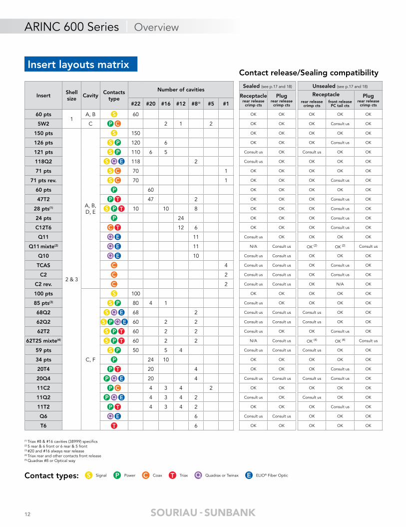
Contact release/Sealing compatibility
InsertShell size
CavityContacts
type
Number of cavitiesSealed (see p.17 and 18) Unsealed (see p.17 and 18)
Receptaclerear release
crimp cts
Plugrear release
crimp cts
Receptacle Plugrear release
crimp cts#22 #20 #16 #12 #8(5) #5 #1 rear releasecrimp cts
front releasePC tail cts
60 pts1
A, B 60 OK OK OK OK OK
5W2 C 2 1 2 OK OK OK Consult us OK
150 pts
2 & 3
A, B, D, E
150 OK OK OK OK OK
126 pts 120 6 OK OK OK Consult us OK
121 pts 110 6 5 Consult us OK Consult us OK OK
118Q2 118 2 Consult us OK OK OK OK
71 pts 70 1 OK OK OK OK OK
71 pts rev. 70 1 OK OK OK Consult us OK
60 pts 60 OK OK OK OK OK
47T2 47 2 OK OK OK Consult us OK
28 pts(1) 10 10 8 OK OK OK Consult us OK
24 pts 24 OK OK OK Consult us OK
C12T6 12 6 OK OK OK Consult us OK
Q11 11 Consult us OK OK OK OK
Q11 mixte(2) 11 N/A Consult us OK (2) OK (2) Consult us
Q10 10 Consult us Consult us OK OK OK
TCAS 4 Consult us Consult us OK Consult us OK
C2 2 Consult us Consult us OK Consult us OK
C2 rev. 2 Consult us Consult us OK N/A OK
100 pts
C, F
100 OK OK OK OK OK
85 pts(3) 80 4 1 Consult us OK OK OK OK
68Q2 68 2 Consult us Consult us Consult us OK OK
62Q2 60 2 2 Consult us Consult us Consult us OK OK
62T2 60 2 2 Consult us OK OK Consult us OK
62T2S mixte(4) 60 2 2 N/A Consult us OK (4) OK (4) Consult us
59 pts 50 5 4 Consult us Consult us Consult us OK OK
34 pts 24 10 OK OK OK OK OK
20T4 20 4 OK OK OK Consult us OK
20Q4 20 4 Consult us Consult us Consult us Consult us OK
11C2 4 3 4 2 OK OK OK OK OK
11Q2 4 3 4 2 Consult us OK Consult us OK OK
11T2 4 3 4 2 OK OK OK Consult us OK
Q6 6 Consult us Consult us OK OK OK
T6 6 OK OK OK OK OK
(1) Triax #8 & #16 cavities (38999) specifi cs(2) 5 rear & 6 front or 6 rear & 5 front(3) #20 and #16 always rear release(4) Triax rear and other contacts front release(5) Quadrax #8 or Optical way
S
S
P C
S P
S P
P
P
S C
S C
S Q E
P T
S P T
TC
Q E
Q E
Q E
C
C
C
S
S P
S Q E
PS Q E
S P T
S P T
S P
P
P T
P Q E
P C
P Q E
P T
Q E
T
Contact types: CoaxPowerSignal Triax ELIO® Fiber OpticQuadrax or TwinaxPS T QC E
Insert layouts matrix
13
ARINC 600 Series | Overview
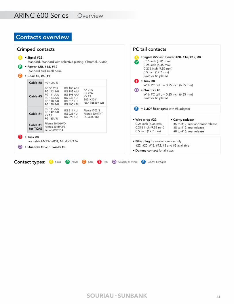
Crimped contacts PC tail contacts
• Signal #22 Standard, Standard with selective plating, Chromel, Alumel
• Power #20, #16, #12 Standard and small barrel
• Coax #8, #5, #1
• Triax #8 For cable EN3375-004, MIL-C-17176
• Quadrax #8 and Twinax #8
Cable #8 RG 400 / U
Cable #5
RG 58 C/URG 142 B/URG 141 A/URG 174 A/URG 178 B/URG 180 B/U
RG 188 A/URG 195 A/URG 196 A/URG 233 / URG 316 / URG 400 / BU
KX 21AKX 22AKX 235021K1011NSA 935359 WB
Cable #1
RG 141 A/URG 142 B/UKX 23RG 165 / U
RG 214 / URG 225 / URG 393 / U
Ficela 1703/3Filotex 50MTKTRG 400 / BU
Cable #1 for TCAS
Filotex E0406WDFilotex 50MFCFBGore SW39214
• Signal #22 and Power #20, #16, #12, #8 0.15 inch (3.81 mm) 0.25 inch (6.35 mm) 0.375 inch (9.52 mm) 0.5 inch (12.7 mm) Gold or tin plated
• Triax #8 With PC tail L = 0.25 inch (6.35 mm)
• Quadrax #8 With PC tail L = 0.25 inch (6.35 mm) Gold or tin plated
• Filler plug for sealed version only #22, #20, #16, #12, #8 and #5 available
• Dummy contact for all sizes
P
S
T
Q
C
PS
T
Q
E • ELIO® fi ber optic with #8 adaptor
• Wire wrap #22 0.25 inch (6.35 mm) 0.375 inch (9.52 mm) 0.5 inch (12.7 mm)
• Cavity reducer #5 to #12, rear and front release #8 to #12, rear release #8 to #16, rear release
Contacts overview
Contact types: CoaxPowerSignal Triax ELIO® Fiber OpticQuadrax or TwinaxPS T QC E

AR
INC
60
0 S
ER
IES
© 2017 SOURIAU - SOURIAU is a registered trademark
Product SeriesTechnical features ................................................................................................... 16
Ordering information .............................................................................................. 17
Sealing level ............................................................................................................ 17
Plating & Grounding ............................................................................................... 18
Dimensions - Shell sizes 1, 2 & 3 ............................................................................ 19
Contacts release ..................................................................................................... 22
Mounting style ........................................................................................................ 22
Inserts arrangement code ....................................................................................... 23
Polarization code .................................................................................................... 24
Packaging code ...................................................................................................... 25
Cost effective version ............................................................................................. 26
ARINC 600 Series

16
ARINC 600 Series | Standard Version
Description• High performance avionic rack equipment rectangular connectors compliant with ARINC 600 specifi cations
• Rack and panel connector
• High density up to 800 signal contacts
• Low insertion force contact design (tapered pin, LIF socket)
• Sealed and unsealed versions
• Multiple polarizing positions
• Field replaceable inserts
• Choice of front and rear removable contacts
• Signal, power, coaxial, twinax, quadrax and optical fi ber contacts
Mechanical
• Shell: Aluminum alloy to QQ-A-591
• Shell plating: Surtec, RoHS Nickel, RoHS Alodine 1200 passivation to MIL-C 5541 class 1
• Insulator: Epoxy resin thermoset Thermoplastic
• Seals and grommets: Fluorinated silicon compliant to MIL-R-25988
• Contact: Copper alloy to QQ-B-626
• Contact plating: Gold plated compliant to MIL-G-45204 over nickel to QQ-N-290
• Endurance: 500 mating cycles • Insertion and extraction forces max: Shell size 1: 120N (27 lbs) Shell size 2: 267N (60 lbs) Shell size 3: 467N (105 lbs)
• Dynamic shock: 3 impacts of 50 g in all axis, duration 11μs (half wave) to MIL-STD-202 method 213
• Vibration: 8 hours in each axis Random at 16.4 g Rms from 50 to 2000 Hz
MIL-STD-1344 A method 2005-1
Electrical
• Dielectric withstanding voltage: Sea level: 1 500 Vrms 15 000 m: 500 Vrms
• Voltage rating: 500 Vac Max 125 Vac at 21 000 m
• Insulation resistance: ≥ 5000 MΩ
• Current ratings, continuous:
* measured over a conductor length of 150 mm
• Quadrax contact size 8 Contact resistance (low level): initial 15 MΩ, after tests 30 MΩ Voltage rating: 500 Vac max 125 Vac at 21 000 m Insulation resistance: at ambient temperature > 5000 MΩ at high temperature > 1000 MΩ Characteristic impedance: 100Ω at 100MHz Attenuation < 0.3 dB at 100 MHz typical per contact pair
Contact to shell continuity
• Triaxial contact size 8 Bandwidth: 0-20 MHz Voltage rating: 500 Vac max 125 Vac at 21 000 m Voltage drop: Inner & middle contact ≤ 55 mV under 1A Outer contact ≤ 75 mV under 12A
• Optical ELIO® Contact ARINC 600 connector can integrate ELIO®
fiber optic contacts in #8 quadrax cavities with the addition of ELIO® #8 adaptor Insertion loss: 0.3 dB per contact Possibility to mix optical and electrical signals in the same insert Flight proven at -65°C +125°C Designed to comply with ELIO® contact optical performances
Environmental
• Temperature rating: -65°C to +125°C
• Fluid resistance: Hydraulic to MIL-H 5606 Lubricating to MIL-L 23699 Isopropyl alcohol
• Resistance to salt spray: 48 hours (MIL-STD-202 method 101 or MIL-STD-1344 method 1001)
• Sealing: Environment resistant (sealed version)
Technical features
ContactWire
gaugeCurrent
(A)Voltage drop
max (mV)*
22222426
532
403025
20202224
7.535
554030
16 16 13 5012 12 23 45
17
ARINC 600 Series | Standard Version
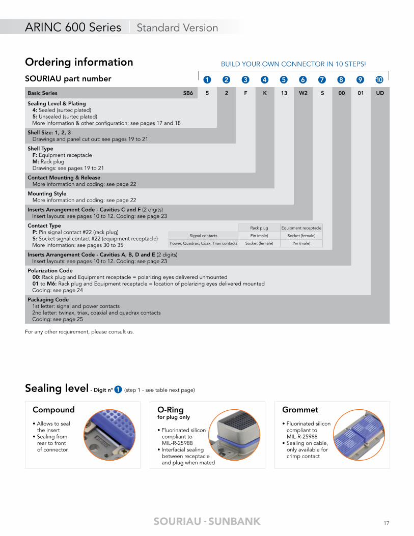
Ordering informationSOURIAU part number
For any other requirement, please consult us.
Basic Series SB6 5 2 F K 13 W2 S 00 01 UD
Sealing Level & Plating 4: Sealed (surtec plated) 5: Unsealed (surtec plated) More information & other confi guration: see pages 17 and 18
Shell Size: 1, 2, 3 Drawings and panel cut out: see pages 19 to 21
Shell Type F: Equipment receptacle M: Rack plug Drawings: see pages 19 to 21
Contact Mounting & Release More information and coding: see page 22
Mounting Style More information and coding: see page 22
Inserts Arrangement Code - Cavities C and F (2 digits) Insert layouts: see pages 10 to 12. Coding: see page 23
Contact Type P: Pin signal contact #22 (rack plug) S: Socket signal contact #22 (equipment receptacle) More information: see pages 30 to 35
Inserts Arrangement Code - Cavities A, B, D and E (2 digits) Insert layouts: see pages 10 to 12. Coding: see page 23
Polarization Code 00: Rack plug and Equipment receptacle = polarizing eyes delivered unmounted 01 to M6: Rack plug and Equipment receptacle = location of polarizing eyes delivered mounted Coding: see page 24
Packaging Code 1st letter: signal and power contacts 2nd letter: twinax, triax, coaxial and quadrax contacts Coding: see page 25
Rack plug Equipment receptacle
Signal contacts Pin (male) Socket (female)
Power, Quadrax, Coax, Triax contacts Socket (female) Pin (male)
1 2 3 4 5 6 7 8 9 10
BUILD YOUR OWN CONNECTOR IN 10 STEPS!
Sealing level - Digit n° (step 1 - see table next page)
Compound
• Allows to seal the insert• Sealing from rear to front of connector
O-Ringfor plug only
• Fluorinated silicon compliant to MIL-R-25988• Interfacial sealing between receptacle and plug when mated
Grommet
• Fluorinated silicon compliant to MIL-R-25988• Sealing on cable, only available for crimp contact
1

18
ARINC 600 Series | Standard Version
Plating & Grounding - Digit n° (step 2 - see table below)
Ground blade
• Cost effective solution• Enables continuity between plug and receptacle• Available in shell sizes 2 & 3• Sealed and unsealed versions
Standardpolarization
• Without specifi c grounding
Ground fi nger
• Cost effective solution• Connection is ensured by a cable on the equipment• Available in shell sizes 1, 2 & 3• Sealed and unsealed versions
Surtec , and Alodine platingor Standard
polarization
• Ground spring mandatory on the plug• Best continuity performance• Available in shell sizes 2 & 3• Sealed and unsealed versions
Nickelor
Select yoursealing
(step 1)
Select yourplating
(step 2)RoHS
Choose your sealing features(step 1)
Choose your grounding option(step 2)
Get yourdigit
n°
SOURIAUbest choice
forCompound O-ringfor plug only Grommet
Standardpolarization
Groundfi nger
Groundblade
Unsealed
Surtec YES* OK 5 New projectsor retrofi t
Nickel YES OK N Best continuityperformances
Alodine No
OK 1
MaintenanceOK OK 9
OK B
OK D
Sealed
Surtec YES*OK OK OK OK 4 New projects
or retrofi tOK 6
Nickel YESOK OK G Best continuity
performancesOK OK OK OK P
Alodine No
OK OK OK OK 0
Maintenance
OK OK OK 2
OK OK 3
OK OK A
OK OK OK OK C
OK OK OK H
OK OK L
* Please confi rm with us confi guration available depending of mounting style. For other specifi cation, please consult us.
1
1
NEW
NEW
NEWRoHS RoHS

19
ARINC 600 Series | Standard Version
Dimensions shell size 1 - Shell size digit n° & Shell type digit n°
Equipment Receptacle (F) (mm/inch)
Rack Plug (M) (mm/inch)
Panel cut out
16.64/16.38.665/.645
3.43
/3.1
8.1
35/.
125
177.
67/1
76.9
16.
995/
6.96
5
161.
42/1
61.1
36.
355/
6.34
59.
78/9
.53
.385
/.37
5
35.61 Max1.402 Max
30.23/29.971.190/1.180
27.99 Max1.102 Max
Six threaded insert for
screw
5.21/4.95.205/.1959.78/9.27.395/.3651.65/1.40.065/.055 3.30/3.05
.130/.120
14.1
0/13
.59
.555
/.53
5
64.0
1/63
.50
2.52
0/2.
500
167.
00/1
65.5
06.
575/
6.55
5
166.
22/1
65.7
16.
544/
6.52
4
4.78/4.67.188/.184
Ø3.84/3.68Ø.151/.145
4.78
/4.6
7.1
88/.
184
28.19/27.691.110/1.090
175
Min
i6.
890
Min
i
161.
296.
350
9.65
.380
Ø4.57/4.22Ø.180/.166
4.85/4.80.191/.189
16.51.650
R3.0
5 M
axR.
120
Max
29.21 Mini1.150 Mini
5.207.205
R0.7
62 M
ax
R.03
0 M
ax
Panel cut out
174.
50 M
ini
6.87
0 M
ini
161.
296.
350
9.14
.360
4.85/4.80.991/.990
16.51.650
R3.0
5 M
axR.
930
Max
23.62 Mini.930 Mini
5.207.205
R7.2
9 M
axR.
287
Max
6.10
Max
.240
Max
25.65/25.151.010/0.990
4.78/4.67.188/.184
10 Screw M2.5
1.65/1.40.065/.055
21.59/21.34.850/.840
3.30/3.05.130/.120
39.50 Max1.555 Max
38.89 Max1.531 Max
31.01 Max1.221 Max
23.11/22.61.910/.890
35.89/35.381.413/1.393
33.45 Max1.317 Max
146.
69/1
46.4
35.
775/
5.76
5
52.9
6/52
.71
2.08
5/2.
075
44.5
8/44
.32
1.75
5/1.
745
13.5
9/13
.08
.535
/.51
5
9.78
/9.2
7.3
85/.
365
152.
53/1
52.2
76.
005/
5.99
5
160.
27/1
59.7
76.
310/
6.29
0
2.92
/2.6
7.1
15/.
105
161.
42/1
61.1
86.
355/
6.34
5
189.
36/1
88.6
07.
455/
7.42
5
9.27
/9.0
7.3
65/.
355
Ø3.84/3.68Ø.151/.145
4.78/4.67.188/.184
4.78/4.67.188/.18416.64/16.38.655/.645
Ø3.18/2.92Ø.125/.115
2 3
Front faceRear face
Front face Rear face
Fron
t fa
ce
Fron
t fa
ce
Note: All dimensions are in millimeters/inches (mm/inch)
20
ARINC 600 Series | Standard Version
Equipment Receptacle (F) (mm/inch)
Rack Plug (M) (mm/inch)
Panel cut out
3.15/3.05.124/.120
3.43
/3.1
8.1
35/.
125
6.32
/6.2
2.2
49/.
245
5.87
/5.6
1.2
31/.
221
35.61 Max1.402 Max
30.23/29.971.190/1.180
27.99 Max1.102 Max
3.30/3.05.130/.120
45.97/45.47.1.810/1.790
Ø3.84/3.68Ø.151/.145
1.65/1.40.065/.056
7.44
/7.1
9.2
93/.
283
166.
22/1
65.7
16.
544/
6.52
4
161.
42/1
61.1
86.
355/
6.34
516.64/16.38.655/.645
4.78/4.67.188/.184
54.2
3/53
.98
2.13
5/2.
125
36.36/36.091.431/1.421
175
Min
i6.
890
Min
i
161.
296.
350
9.65
.380
Ø4.57/4.22Ø.180/.166
36.221.426
16.51.650
R3.0
5 M
ax
R.12
0 M
ax
46.99 Mini1.850 Mini
5.207.205
R0.7
65 M
ax
R.03
0 M
ax
4.85/4.80.191/.189
9.78
/9.5
3.3
85/.
375
177.
67/1
76.9
16.
995/
6.96
5
169.
24/1
68.9
96.
663/
6.65
3
Panel cut out
166.
22/1
65.7
16.
544/
6.52
4
161.
296.
350
9.14
.360
Ø4.57/4.22Ø.180/.166
36.221.426
R3.05 Max
R.120 Max
5.207.205
R7.2
9 M
axR.
180
Max
174.
5 M
ini
6.87
0 M
ini
Ø3.84/3.68Ø.151/.145
4.78/4.67.188/.184
1.65/1.40.065/.0553.30/3.05.130/.120
38.89 Max1.531 Max
31.01 Max1.221 Max
45.97/45.471.810/1.790
33.45 Max1.317 Max
54.2
3/53
.98
2.13
5/2.
125
11.6
8/11
.43
.460
/.45
0
177.
16/1
76.4
06.
975/
6.94
5
9.27
/9.0
2.3
65/.
355
36.35/36.091.431/1.421
16.64/16.38.655/.645
54.1
02.
130
38.86 Mini1.530 Mini
4.85/4.80.191/.189
6.60/5.84.260/.230
16.51.650
55.8
8 M
ini
2.20
0 M
ini
70.6
1 M
ax2.
780
Max
6.10
Max
.240
Max
2.92
/2.6
7.1
15/.
105
6.93
/6.6
8.2
73/.
283
161.
42/1
61.1
26.
355/
6.34
5
Front faceRear face
Fron
t fa
ce
Front face Rear face
Fron
t fa
ce
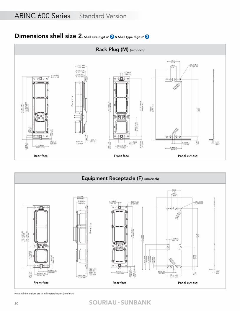
Dimensions shell size 2 - Shell size digit n° & Shell type digit n°2 3
Note: All dimensions are in millimeters/inches (mm/inch)
21
ARINC 600 Series | Standard Version
Equipment Receptacle (F) (mm/inch)
Rack Plug (M) (mm/inch)
Panel cut out
3.15/3.05.124/.120
3.45
/3.1
8.1
35/.
125
6.32
/6.2
2.2
49/.
245
5.87
/5.6
1.2
31/.
221
35.61 Max1.402 Max
27.99 Max1.102 Max
3.30/3.05.130/.120
83.19/82.423.275/3.245
1.65/1.40.065/.056
7.44
/7.1
9.2
93/.
283
166.
22/1
65.7
16.
544/
6.52
4
30.23/29.971.190/1.180
4.78/4.67.188/.184
Ø3.84/3.68Ø.151/.145
175
Min
i6.
890
Min
i
161.
296.
350
9.65
.380
Ø4.57/4.22Ø.180/.166
73.32.886
49.531.950
R3.0
5 M
ax
R.12
0 M
ax
84.07 Mini3.310 Mini
5.207.205
R0.762
Max
R.030 M
ax
4.85/4.80.191/.189
177.
67/1
76.9
16.
995/
6.96
5
169.
24/1
68.9
96.
663/
6.65
3
16.51.650
9.78
/9.5
3.3
85/.
375
54.2
3/53
.98
2.13
5/2.
125
161.
54/1
61.0
46.
360/
6.34
0
73.43/73.182.891/2.881 49.66/49.40
1.955/1.94516.64/16.38.655/.645
Panel cut out
166.
22/1
65.7
16.
544/
6.52
4
161.
296.
350
9.14
.360
73.32.886
R3.05 Max
R.120 Max
5.207.205
R7.29 Max
R.180 Max
174.
5 M
ini
6.87
0 M
ini
Ø3.84/3.68Ø.151/.145
4.78/4.67.188/.184
1.65/1.40.065/.0553.30/3.05.130/.120
38.89 Max1.531 Max
31.01 Max1.221 Max
4.78/4.67.188/.184
33.45 Max1.317 Max
54.2
3/53
.98
2.13
5/2.
125
11.6
8/11
.43
.460
/.45
0
9.27
/9.0
2.3
65/.
355
16.64/16.38.655/.645
54.1
02.
130
76.2 Mini3.00 Mini
4.85/4.80.191/.189
24.38/23.62.960/.930
16.51.650
55.8
8 M
ini
2.20
0 M
ini
70.6
1 M
ax2.
780
Max
6.10
.240
6.93
/6.6
8.2
73/.
283
161.
42/1
61.1
26.
355/
6.34
5
2.92
/2.6
7.1
15/.
105
49.66/49.401.955/1.945
73.43/73.182.891/2.881
177.
16/1
76.4
06.
975/
6.94
5
83.19/82.423.275/3.245
49.531.950
Front faceRear face
Front face Rear face
Fron
t fa
ce
Fron
t fa
ce
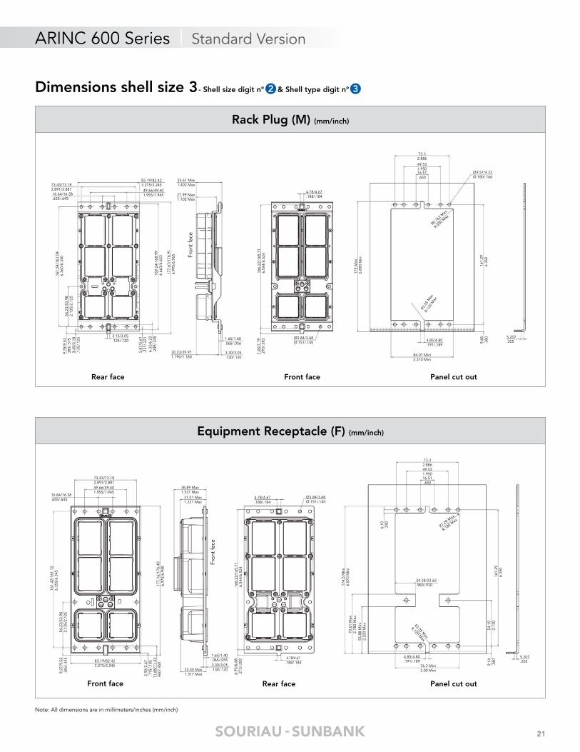
Dimensions shell size 3 - Shell size digit n° & Shell type digit n°2 3
Note: All dimensions are in millimeters/inches (mm/inch)
22
ARINC 600 Series | Standard Version
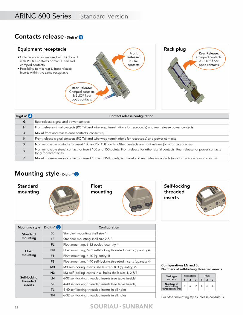
Mounting style - Digit n°
Contacts release - Digit n° 4
5
Digit n° Contact release confi guration
G Rear release signal and power contacts
H Front release signal contacts (PC Tail and wire wrap terminations for receptacle) and rear release power contacts
J Mix of front and rear release contacts (consult us)
K Front release signal contacts (PC Tail and wire wrap terminations for receptacle) and power contacts
X Non removable contacts for insert 100 and/or 150 points. Other contacts are front release (only for receptacles)
Y Non removable signal contact for insert 100 and 150 points. Front release for other signal contacts. Rear release for power contacts (only for receptacles)
Z Mix of non-removable contact for insert 100 and 150 points, and front and rear release contacts (only for receptacles) - consult us
Equipment receptacle
• Only receptacles are used with PC board with PC tail contacts or mix PC tail and crimped contacts• Possibility to mix rear & front release inserts within the same receptacle
Rack plugFront
Release:PC Tail
contacts
Rear Release:Crimped contacts
& ELIO® fi beroptic contacts
Rear Release:Crimped contacts
& ELIO® fi beroptic contacts
4
Floatmounting
Self-locking threaded inserts
Standard mounting
Mounting style Digit n° Confi guration
Standardmounting
05 Standard mounting shell size 1
13 Standard mounting shell size 2 & 3
Floatmounting
FL Float mounting, 6-32 eyelet (quantity 4)
FN Float mounting, 6-32 self-locking threaded inserts (quantity 4)
FT Float mounting, 4-40 (quantity 4)
FS Float mounting, 4-40 self-locking threaded inserts (quantity 4)
Self-locking threaded
inserts
M3 M3 self-locking inserts, shells size 2 & 3 (quantity: 2)
N3 M3 self-locking inserts in all holes shells size 1, 2 & 3
LN 6-32 self-locking threaded inserts (see table beside)
SL 4-40 self-locking threaded inserts (see table beside)
TL 4-40 self-locking threaded inserts in all holes
TN 6-32 self-locking threaded inserts in all holes For other mounting styles, please consult us.
Shell typeand size
Receptacle Plug
1 2 3 1 2 3
Numbers ofself-locking
threaded inserts4 6 10 4 4 8
Confi gurations LN and SLNumbers of self-locking threaded inserts
5
23
ARINC 600 Series | Standard Version
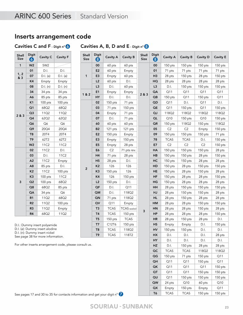
Cavities C and F - Digit n°
Inserts arrangement code
Shell Size
DigitCavity C Cavity F
1 W2 5W2
1, 2 & 3
01 D.I. D.I.
07 D.I. (a) D.I. (a)
K4 Empty Empty
2 & 3
08 D.I. (n) D.I. (n)
34 34 pts 34 pts
A6 85 pts 85 pts
K1 100 pts 100 pts
Q1 68Q2 68Q2
Q3 11Q2 11Q2
Q4 62Q2 62Q2
Q6 Q6 Q6
Q9 20Q4 20Q4
T8 20T4 20T4
T9 62T2 62T2
W2 11C2 11C2
3
02 11C2 D.I.
03 D.I. 11C2
A2 11C2 Empty
A8 85 pts D.I.
K2 11C2 100 pts
K3 100 pts 11C2
Q2 100 pts 68Q2
Q8 68Q2 85 pts
QA 34 pts Q6
R1 11Q2 68Q2
R2 11Q2 100 pts
R3 11Q2 Empty
R4 68Q2 11Q2
For other inserts arrangement code, please consult us.
D.I.: Dummy insert polyamideD.I. (a): Dummy insert alodineD.I. (n): Dummy insert nickelSee page 38 for more information.
Shell Size
DigitCavity A Cavity B
1
00 60 pts 60 pts
E2 60 pts Empty
E3 Empty 60 pts
L2 60 pts D.I.
L3 D.I. 60 pts
1 & 2E1 Empty Empty
HY D.I. D.I.
2
02 150 pts 71 pts
03 71 pts 150 pts
04 Empty 71 pts
07 D.I. 71 pts
60 60 pts 60 pts
B2 121 pts 121 pts
E2 150 pts Empty
E3 Empty 150 pts
E5 Empty 28 pts
E6 C2 71 pts rev.
H4 71 pts 28 pts
H5 28 pts D.I.
K2 126 126
K3 150 pts 126
K4 126 150 pts
L2 150 pts D.I.
QF D.I. Q11
QM D.I. 118Q2
QN 71 pts 118Q2
QV Q11 Empty
T3 TCAS TCAS sealed
T4 TCAS 150 pts
T5 150 pts TCAS
T7 C12T6 150 pts
T8 TCAS 118Q2
T9 TCAS 118T2
Shell Size
DigitCavity A Cavity B Cavity D Cavity E
2 & 3
00 150 pts 150 pts 150 pts 150 pts
01 71 pts 71 pts 71 pts 71 pts
H3 28 pts 150 pts 28 pts 150 pts
HQ 28 pts 28 pts 28 pts 28 pts
L3 D.I. 150 pts 150 pts 150 pts
QA Q11 Q11 Q11 Q11
QB 150 pts Q11 150 pts Q11
QD Q11 D.I. Q11 D.I.
QE Q11 150 pts Q11 150 pts
QJ 118Q2 118Q2 118Q2 118Q2
QL Q10 150 pts Q10 150 pts
QR 150 pts 118Q2 150 pts 118Q2
3
05 C2 C2 Empty 150 pts
09 150 pts 150 pts 150 pts 71 pts
78 TCAS TCAS D.I. 150 pts
E7 C2 C2 C2 150 pts
HA 150 pts 150 pts 150 pts 28 pts
HB 150 pts 150 pts 28 pts 150 pts
HC 150 pts 150 pts 28 pts 28 pts
HD 150 pts 28 pts 150 pts 150 pts
HE 150 pts 28 pts 150 pts 28 pts
HF 150 pts 28 pts 28 pts 150 pts
HG 150 pts 28 pts 28 pts 28 pts
HH 28 pts 150 pts 150 pts 150 pts
HJ 28 pts 150 pts 150 pts 28 pts
HL 28 pts 150 pts 28 pts 28 pts
HM 28 pts 28 pts 150 pts 150 pts
HN 28 pts 28 pts 150 pts 28 pts
HP 28 pts 28 pts 28 pts 150 pts
HR 28 pts 150 pts 28 pts D.I.
HS Empty Empty D.I. 150 pts
HV 150 pts 150 pts D.I. D.I.
HX D.I. D.I. D.I. 28 pts
HY D.I. D.I. D.I. D.I.
HZ D.I. 150 pts 28 pts 28 pts
QC TCAS TCAS 118Q2 118Q2
QG 150 pts 71 pts 150 pts Q11
QH Q11 Q11 150 pts Q11
QK Q11 Q11 Q11 150 pts
QT Q11 Q11 150 pts 150 pts
QU Q11 150 pts 150 pts 150 pts
QW 24 pts Q10 60 pts Q10
QX Empty 150 pts Empty Q11
T6 TCAS TCAS 150 pts 150 pts
Cavities A, B, D and E - Digit n°6
7
8
See pages 17 and 30 to 35 for contacts information and get your digit n°
6 88

24
ARINC 600 Series | Standard Version
Polarization code - Digit n°
Code Receptacle Plug
No
rmal
ized
SO
UR
IAU
Left
key
Cen
ter
key
Rig
ht k
ey
Left
po
st
Cen
ter
po
st
Rig
ht p
ost
00 00 - - - - - -01 01 4 4 4 1 1 102 02 4 4 3 2 1 103 03 4 4 2 3 1 104 04 4 4 1 4 1 105 05 4 4 6 5 1 106 06 4 4 5 6 1 107 07 5 4 4 1 1 608 08 5 4 3 2 1 609 09 5 4 2 3 1 610 10 5 4 1 4 1 611 11 5 4 6 5 1 612 12 5 4 5 6 1 613 13 6 4 4 1 1 514 14 6 4 3 2 1 515 15 6 4 2 3 1 516 16 6 4 1 4 1 517 17 6 4 6 5 1 518 18 6 4 5 6 1 519 19 1 4 4 1 1 420 20 1 4 3 2 1 421 21 1 4 2 3 1 422 22 1 4 1 4 1 423 23 1 4 6 5 1 424 24 1 4 5 6 1 425 25 2 4 4 1 1 326 26 2 4 3 2 1 327 27 2 4 2 3 1 328 28 2 4 1 4 1 329 29 2 4 6 5 1 330 30 2 4 5 6 1 331 31 3 4 4 1 1 232 32 3 4 3 2 1 233 33 3 4 2 3 1 234 34 3 4 1 4 1 235 35 3 4 6 5 1 236 36 3 4 5 6 1 237 37 4 3 4 1 2 138 38 4 3 3 2 2 139 39 4 3 2 3 2 140 40 4 3 1 4 2 141 41 4 3 6 5 2 142 42 4 3 5 6 2 143 43 5 3 4 1 2 644 44 5 3 3 2 2 645 45 5 3 2 3 2 646 46 5 3 1 4 2 647 47 5 3 6 5 2 648 48 5 3 5 6 2 649 49 6 3 4 1 2 550 50 6 3 3 2 2 551 51 6 3 2 3 2 552 52 6 3 1 4 2 553 53 6 3 6 5 2 5
Code Receptacle PlugN
orm
aliz
ed
SO
UR
IAU
Left
key
Cen
ter
key
Rig
ht k
ey
Left
po
st
Cen
ter
po
st
Rig
ht p
ost
54 54 6 3 5 6 2 555 55 1 3 4 1 2 456 56 1 3 3 2 2 457 57 1 3 2 3 2 458 58 1 3 1 4 2 459 59 1 3 6 5 2 460 60 1 3 5 6 2 461 61 2 3 4 1 2 362 62 2 3 3 2 2 363 63 2 3 2 3 2 364 64 2 3 1 4 2 365 65 2 3 6 5 2 366 66 2 3 5 6 2 367 67 3 3 4 1 2 268 68 3 3 3 2 2 269 69 3 3 2 3 2 270 70 3 3 1 4 2 271 71 3 3 6 5 2 272 72 3 3 5 6 2 273 73 4 2 4 1 3 174 74 4 2 3 2 3 175 75 4 2 2 3 3 176 76 4 2 1 4 3 177 77 4 2 6 5 3 178 78 4 2 5 6 3 179 79 5 2 4 1 3 680 80 5 2 3 2 3 681 81 5 2 2 3 3 682 82 5 2 1 4 3 683 83 5 2 6 5 3 684 84 5 2 5 6 3 685 85 6 2 4 1 3 586 86 6 2 3 2 3 587 87 6 2 2 3 3 588 88 6 2 1 4 3 589 89 6 2 6 5 3 590 90 6 2 5 6 3 591 91 1 2 4 1 3 492 92 1 2 3 2 3 493 93 1 2 2 3 3 494 94 1 2 1 4 3 495 95 1 2 6 5 3 496 96 1 2 5 6 3 497 97 2 2 4 1 3 398 98 2 2 3 2 3 399 99 2 2 2 3 3 3
100 A0 2 2 1 4 3 3101 A1 2 2 6 5 3 3102 A2 2 2 5 6 3 3103 A3 3 2 4 1 3 2104 A4 3 2 3 2 3 2105 A5 3 2 2 3 3 2106 A6 3 2 1 4 3 2107 A7 3 2 6 5 3 2
Code Receptacle Plug
No
rmal
ized
SO
UR
IAU
Left
key
Cen
ter
key
Rig
ht k
ey
Left
po
st
Cen
ter
po
st
Rig
ht p
ost
108 A8 3 2 5 6 3 2109 A9 4 1 4 1 4 1110 B0 4 1 3 2 4 1111 B1 4 1 2 3 4 1112 B2 4 1 1 4 4 1113 B3 4 1 6 5 4 1114 B4 4 1 5 6 4 1115 B5 5 1 4 1 4 6116 B6 5 1 3 2 4 6117 B7 5 1 2 3 4 6118 B8 5 1 1 4 4 6119 B9 5 1 6 5 4 6120 C0 5 1 5 6 4 6121 C1 6 1 4 1 4 5122 C2 6 1 3 2 4 5123 C3 6 1 2 3 4 5124 C4 6 1 1 4 4 5125 C5 6 1 6 5 4 5126 C6 6 1 5 6 4 5127 C7 1 1 4 1 4 4128 C8 1 1 3 2 4 4129 C9 1 1 2 3 4 4130 D0 1 1 1 4 4 4131 D1 1 1 6 5 4 4132 D2 1 1 5 6 4 4133 D3 2 1 4 1 4 3134 D4 2 1 3 2 4 3135 D5 2 1 2 3 4 3136 D6 2 1 1 4 4 3137 D7 2 1 6 5 4 3138 D8 2 1 5 6 4 3139 D9 3 1 4 1 4 2140 E0 3 1 3 2 4 2141 E1 3 1 2 3 4 2142 E2 3 1 1 4 4 2143 E3 3 1 6 5 4 2144 E4 3 1 5 6 4 2145 E5 4 6 4 1 5 1146 E6 4 6 3 2 5 1147 E7 4 6 2 3 5 1148 E8 4 6 1 4 5 1149 E9 4 6 6 5 5 1150 F0 4 6 5 6 5 1151 F1 5 6 4 1 5 6152 F2 5 6 3 2 5 6153 F3 5 6 2 3 5 6154 F4 5 6 1 4 5 6155 F5 5 6 6 5 5 6156 F6 5 6 5 6 5 6157 F7 6 6 4 1 5 5158 F8 6 6 3 2 5 5159 F9 6 6 2 3 5 5160 G0 6 6 1 4 5 5161 G1 6 6 6 5 5 5
Code Receptacle Plug
No
rmal
ized
SO
UR
IAU
Left
key
Cen
ter
key
Rig
ht k
ey
Left
po
st
Cen
ter
po
st
Rig
ht p
ost
162 G2 6 6 5 6 5 5163 G3 1 6 4 1 5 4164 G4 1 6 3 2 5 4165 G5 1 6 2 3 5 4166 G6 1 6 1 4 5 4167 G7 1 6 6 5 5 4168 G8 1 6 5 6 5 4169 G9 2 6 4 1 5 3170 H0 2 6 3 2 5 3171 H1 2 6 2 3 5 3172 H2 2 6 1 4 5 3173 H3 2 6 6 5 5 3174 H4 2 6 5 6 5 3175 H5 3 6 4 1 5 2176 H6 3 6 3 2 5 2177 H7 3 6 2 3 5 2178 H8 3 6 1 4 5 2179 H9 3 6 6 5 5 2180 J0 3 6 5 6 5 2181 J1 4 5 4 1 6 1182 J2 4 5 3 2 6 1183 J3 4 5 2 3 6 1184 J4 4 5 1 4 6 1185 J5 4 5 6 5 6 1186 J6 4 5 5 6 6 1187 J7 5 5 4 1 6 6188 J8 5 5 3 2 6 6189 J9 5 5 2 3 6 6190 K0 5 5 1 4 6 6191 K1 5 5 6 5 6 6192 K2 5 5 5 6 6 6193 K3 6 5 4 1 6 5194 K4 6 5 3 2 6 5195 K5 6 5 2 3 6 5196 K6 6 5 1 4 6 5197 K7 6 5 6 5 6 5198 K8 6 5 5 6 6 5199 K9 1 5 4 1 6 4200 L0 1 5 3 2 6 4201 L1 1 5 2 3 6 4202 L2 1 5 1 4 6 4203 L3 1 5 6 5 6 4204 L4 1 5 5 6 6 4205 L5 2 5 4 1 6 3206 L6 2 5 3 2 6 3207 L7 2 5 2 3 6 3208 L8 2 5 1 4 6 3209 L9 2 5 6 5 6 3210 M0 2 5 5 6 6 3211 M1 3 5 4 1 6 2212 M2 3 5 3 2 6 2213 M3 3 5 2 3 6 2214 M4 3 5 1 4 6 2215 M5 3 5 6 5 6 2216 M6 3 5 5 6 6 2
9
Left hand key Center key
Right hand key
Location of polarizing keys (view of engaging face)
Black area represents key positionPolarizing post - Rack plug
Polarizing postEquipment receptacle
Key Key
1 2 3 4 5 6
9 9 9 9

25
ARINC 600 Series | Standard Version
Packaging code - 1st letter + 2nd letter = Digit n°
For other code packaging, please consult us.
10
Contact type Signal contacts Power contactsPC Tail length
(mm/inch)PC Tail plating 1st letter
Crimp contactsonly
Delivered without contactsDelivered without contacts N/A N/A L
Delivered with contacts N/A N/A N
Delivered with contactsDelivered with contacts N/A N/A A
Delivered without contacts N/A N/A B
MixPC Tail + Crimp contacts
Delivered withPC Tail contacts
Delivered withcrimp contacts
3.81/0.125 Tin plated I
6.35/0.25Tin plated 3
Gold plated E
9.52/0.375 Tin plated P
PC Tail contactsonly
Delivered with contacts Delivered without contacts 3.81/0.125 Gold plated G
Delivered with contacts Delivered with contacts6.35/0.25
Tin plated H
Gold plated Y
Delivered without contacts Delivered with contacts Tin plated 5
Delivered with contacts Delivered without contacts 9.52/0.375 Gold plated R
Delivered with contacts Delivered with contacts
12.7/0.5
Tin plated 4
Delivered with contacts Delivered without contactsTin plated 2
Gold plated X
Delivery conditions of Signal and Power contacts - Digit n° (1st letter - see table below)10
Delivery conditions of #5 Coax, #1 Coax and #8 Quadrax contacts - Digit n° (2nd letter - see table below)10
#5 Coax contacts #1 Coax contacts 2nd letter
Delivered with #5 coax for RG 58 C/U cable Delivered with #1 coax for RG165/U and RG 225/U cable A
Delivered with #5 coax for 5021K1011 cable Delivered with #1 coax for RG 393/U cable F
Delivered with #5 coax for 5021K1011 cable
Delivered without contacts
D
Delivered with #5 coax for RG 316 cable J
Delivered with #5 coax for KX23 cable K
Delivered with #5 coax for RG 58C/U cable M
Delivered with #5 to #12 cavity reducer I
Delivered with #5 dummy contacts H
Delivered without contacts
N
Delivered with #1 TCAS Coax S
Delivered with #1 coax for RG 141A/U, RG 142 and KX23 cable B
Delivered with #1 coax for UT 141 and RG 400B/U cable C
Delivered with #1 coax for RG 393/U cable E
#8 Quadrax contacts 2nd letter
• If signal and power contacts are crimped, delivered with crimp Quadrax contacts• If not, delivered with PC tails Quadrax contacts. Same plating than signal and power contacts, or tin plated if not applicable. Q
Packaging code not applicable to connectors where no contacts are specifi ed.Do not use the suffi x L (1st letter) and N (2nd letter) together.

26
ARINC 600 Series | Cost Effective Version
Mechanical
• Shell: Aluminum alloy to QQ-A-591
• Shell plating: Nickel Alodine 1200 passivation to MIL-C-5541 class 1
• Contact: Copper alloy to QQ-B-626
• Contact plating: Gold plated compliant to MIL-G-45204 over nickel to QQ-N290
• Insulator: Thermoplastic
• Endurance: 500 mating/unmating operations
• Insertion and extraction forces max: Shell size 2: 267N (60 lbs) Shell size 3: 467N (105 lbs)
• Vibrations: 8 hours in each axis Random vibration at 16.4 g Rms from 50 to 2000 Hz (MIL-STD-1344 A method 2005-1)
• Dynamic shock: 3 impacts of 50 g in all axis, duration 11μs (half wave) to MIL-STD-202 method 213
Environmental
• Operating temperature: -65°C to +125°C
• Resistance to salt spray: 48 hours (MIL-STD-202 method 101 or MIL-STD-1344 method 1001)
Electrical
• Dielectric withstanding voltage:
• Voltage rating: 500 Vac Max 125 Vac at 21000 m
• Insulation resistance: ≥ 5000 MΩ
Description• High performance avionic equipment
• Rack and panel rectangular connectors compliant to ARINC 600 specifi cations
• High density up to 800 signal contacts
• Low insertion force contact design (tapered pin, LIF socket)
• Unsealed versions
• Multiple polarizing positions
• Field replaceable inserts, featuring: - Non removable contacts - Signal contacts
Technical features
Sea level 15 000 m
Mated 1500 Vrms 500 Vrms
Unmated 1500 Vrms 500 Vrms

27
ARINC 600 Series | Cost Effective Version
Standard insert
Cost effective inserts
Comparison with standard ARINC 600
Do you see any difference between
these two connectors?
The technical characteristics of the Cost Effective ARINC compared to the Standard are:
• Selective gold plating - Active part • Non removable contacts • Insert modifi cation (one piece part) • No contact marking, no insert marking • Insert always pre-loaded with contacts This technology allows you
to SAVE money!
Possibility to MIX cost effective and
standard inserts in the same shell
Cost Effective ARINCStandard ARINC
No? Read below
In Addition:

AR
INC
60
0 S
ER
IES
© 2015 SOURIAU - SOURIAU is a registratred trademark
Common SectionCrimp contacts: Signal contacts, Power contacts, Twinax contacts, Triax contacts ...................... 30 Coax contacts ..................................................................................................... 31 Specifi c contacts for 28 pts insert, Wire data for crimp contacts ....................... 32
PC tail contacts: Signal contacts, Power contacts, Triax contacts, Coax contacts ........................ 33 Specifi c contacts for 62Q2 and 121 pts inserts .................................................. 34
Wire wrap contacts .................................................................................................. 34
Quadrax contats ...................................................................................................... 35
ELIO® fi ber optic contacts + Adaptors #8 ............................................................... 35
Tooling: Crimping tools .................................................................................................... 36 Insertion and extraction tools + Instructions ...................................................... 37
Accessories: Cavity reducers, Dummy contacts, Filler plug, Dummy inserts .......................... 38 Plastic covers, Backshells SUNBANK ................................................................. 39
ARINC 600 Series
30
ARINC 600 Series | Common Section
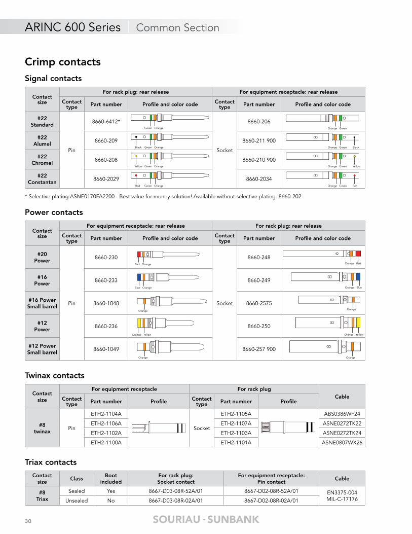
Crimp contacts
Contact size
For rack plug: rear release For equipment receptacle: rear release
Contact type Part number Profi le and color code Contact
type Part number Profi le and color code
#22Standard
Pin
8660-6412*
Socket
8660-206
#22Alumel
8660-209 8660-211 900
#22Chromel
8660-208 8660-210 900
#22Constantan
8660-2029 8660-2034
Signal contacts
* Selective plating ASNE0170FA2200 - Best value for money solution! Available without selective plating: 8660-202
Green Orange
Black Green Orange
Yellow Green Orange
Red Green Orange
Orange Green Black
Orange Green Yellow
Orange Green Red
Orange Green
Power contacts
Orange
Orange
Orange Yellow
Red Orange
Blue Orange
Orange
Orange
Orange Red
Orange Blue
Orange Yellow
Contact size
For equipment receptacle: rear release For rack plug: rear release
Contact type Part number Profi le and color code Contact
type Part number Profi le and color code
#20Power
Pin
8660-230
Socket
8660-248
#16Power
8660-233 8660-249
#16 PowerSmall barrel
8660-1048 8660-2575
#12Power
8660-236 8660-250
#12 PowerSmall barrel
8660-1049 8660-257 900
Triax contacts
Contactsize
ClassBoot
includedFor rack plug:Socket contact
For equipment receptacle:Pin contact
Cable
#8Triax
Sealed Yes 8667-D03-08R-52A/01 8667-D02-08R-52A/01 EN3375-004MIL-C-17176Unsealed No 8667-D03-08R-02A/01 8667-D02-08R-02A/01
Twinax contacts
Contactsize
For equipment receptacle For rack plugCableContact
type Part number Profi le Contact type Part number Profi le
#8twinax
Pin
ETH2-1104A
Socket
ETH2-1105A ABS0386WF24
ETH2-1106A ETH2-1107A ASNE0272TK22
ETH2-1102A ETH2-1103A ASNE0272TK24
ETH2-1100A ETH2-1101A ASNE0807WX26

31
ARINC 600 Series | Common Section
Coax contacts
Contactsize
ClassFor rack plug:Socket contact
For equipmentreceptacle: Pin contact
Cable
#8 Coax Unsealed 8660-6211 8660-6251 RG 400 / U
#5 Coax
(Sealing sleeve
supplied for sealed
connectors)
Sealed 8660-2485 8660-2480 RG 58 C / URG 142 B / URG 141 A / U
NSA 935359 WBUnsealed 8660-2285 900 8660-2280
Sealed 8660-2486 8660-2481 RG 174 A / URG 188 A / UUnsealed 8660-2286 8660-2281
Sealed 8660-2487 8660-2482 RG 223 / URG 400 BU
KX 23Unsealed 8660-2287 8660-2282
Sealed 8660-2488 8660-2483 RG 178 B / URG 196 A / URG 316 / U
KX 21 AKX 22 AUnsealed 8660-2288 8660-2283
Sealed 8660-2489 8660-2484 RG 180 B / URG 195 A / UUnsealed 8660-2289 8660-2284
Sealed 8660-2298E -5021 K 1011
Unsealed 8660-2498E 8660-2494
Contactsize
ClassFor rack plug: Socket contact For equipment receptacle: Pin contact
CableCoax body Termination
kitCoax
assembly Coax body Terminationkit
Coaxassembly
#1 Coax
Sealed 8660-22778660-2587 900
8660-2296 900 8660-2272 9008660-2581 900
8660-2251 900 RG 141 A / URG 142 B / U
KX 23Unsealed 8660-2278 900 8660-2261 900 8660-2274 900 8660-2241 900
Sealed- - -
8660-2272 9008660-2582 900
8660-2252 900UT141
Unsealed 8660-2274 900 8660-2242
Sealed 8660-22778660-2580 900
8660-2295 900 8660-2272 9008660-2583 900
8660-2250 900 RG 165 / URG 214 / URG 225 / UUnsealed 8660-2278 900 8660-2260 900 8660-2274 900 8660-2240 900
Sealed 8660-22778660-2585 900
8660-2299 8660-2272 9008660-2588 900
8660-2254 900RG 393 / U
Unsealed 8660-2278 900 8660-2263 900 8660-2274 900 8660-2244
Sealed 8660-22778660-2237 900
8660-2311 8660-2272 9008660-2236 900
8660-2313 900 Fileca1703 / 3Filotex50MT
KTUnsealed 8660-2278 900 8660-2259 900 8660-2274 900 8660-2314 900
Unsealed 8660-2278 900 8660-2341 900 8660-2141 900 - - - RG 400 / BU
Coax assembly example
Coax body Termination kit
Coax assembly
Contactsize
Shellstyle
Part number Profi le Cable
#1 Coax for TCAS
insert
Rackplug
8660-D21-100-01A/05 FILOTEX E0406WDFILOTEX 50MFCFB
8660-6413 GORESW39214
Equipment receptacle 8660-6136 Output SMA
Coax female contact
Sealingsleeve
Crimp ferrule
Inner contact
Female body
Coax male contact
Sealingsleeve
Crimp ferrule
Inner contact
Male body

32
Specifi c crimp contacts for 28 pts insert
ARINC 600 Series | Common Section
#16 Power rear release
#8 Triaxial contact
#16 Dummy contacts (unsealed version)
28 pts
10 #2210 #16
8 #8
Specifi c contacts10 #16 & 8 #8
Wire data for crimp contacts
Yellow Blue Orange
Red Green Orange
Note: All dimensions are in millimeters/inches (mm/inch)
Contactsize
ClassFor rack plug:Socket contact
For equipmentreceptacle:Pin contact
Cable
#8Triaxial
Sealed 8599-5220 900Included boot
8599-5210 900Included boot MIL-C17176
-00002Unsealed 8599-0998 8599-0988
Contactsize
Contact type
Part numberwithout colour code
MIL-DTL-38999 contactsPart number Profi le and colour code
#16Power
Pin 8599-0704 MJ M39029/58-364
Socket 8599-0708 900 M39029/56-352
Contactsize
Shellstyle
Part number Color
#16(38999)
Rackplug 8660-3138
BlueEquipment receptacle 8660-3139
Contact size
Cables Ø over insulation (mm/inch)
mm² AWG min max
#22 0.15 to 0.38 26 - 24 - 22 0.66 / 0.026 1.371 / 0.054
#20 0.21 to 0.60 24 - 22 - 20 1.016 / 0.04 1.803 / 0.071
#16 0.60 to 1.34 20 - 18 - 16 1.727 / 0.068 2.616 / 0.103
#16Small barrel
0.21 to 0.93 24 - 22 - 20 - 18 1.73 / 0.068 2.6 / 0.102
#12 1.91 to 3.18 14 - 12 2.464 / 0.097 3.429 / 0.135
#12Small barrel
0.21 to 0.93 24 - 22 - 20 - 18 2.48 / 0.098 3.4 / 0.134

33
ARINC 600 Series | Common Section
PC tail contacts
Note: All dimensions are in millimeters/inches (mm/inch)
Signal contactsFor equipment receptacle: Socket contacts - front release
LTin plated
Orange Green
LGold plated
Contact size Gold plated Tin platedL = Length
PC tailØ PC tail Profi le
#22
8660-550 8660-C23-22V-01A/06 3.81 / 0.15
0.60 / 0.024 min0.67 / 0.026 max
8660-555 8660-C23-22V-02A/06 6.35 / 0.25
8660-560 8660-C23-22V-03A/06 9.52 / 0.375
8660-565 900 8660-C23-22V-04A/06 12.7 / 0.5
Power contactsFor equipment receptacle: Pin contacts - front release
L
L
L
Contact size Gold plated Tin platedL = Length
PC tailØ PC tail Profi le
#20
8660-420-200-04AMJ 8660-420-200-04A06 3.81 / 0.15
0.81 / 0.032 min0.88 / 0 .035 max
8660-420-200-01AMJ 8660-420-200-01A06 6.35 / 0.25
8660-420-200-02AMJ 8660-420-200-02A06 9.52 / 0.375
8660-420-200-03AMJ 8660-420-200-03A06 12.7 / 0.5
#16
8660-420-160-04AMJ 8660-420-160-04A06 3.81 / 0.15
1.27 / 0.050 min1.33 / 0.052 max
8660-420-160-01AMJ 8660-420-160-01A06 6.35 / 0.25
8660-420-160-02AMJ 8660-420-160-02A06 9.52 / 0.375
8660-420-160-03AMJ 8660-420-160-03A06 12.7 / 0.5
#12
8660-420-120-04AMJ 8660-420-120-04A06 3.81 / 0.15
2.05 / 0.081 min2.11 / 0.083 max
8660-420-120-01AMJ 8660-420-120-01A06 6.35 / 0.25
8660-420-120-02AMJ 8660-420-120-02A06 9.52 / 0.375
8660-420-120-03AMJ 8660-420-120-03A06 12.7 / 0.5
#8 Please consult us
Triax contactsFor equipment receptacle: Pin contacts - front release
Contact size Tin plated L = Length PC tail Profi le
#8 8660-6046 6.35 / 0.25
Coax contactsFor equipment receptacle: Pin contacts - front release
Contact size Tin plated L = Length PC tail Profi le
#8 8660-6271 6.35 / 0.25

34
Specifi c PC tail contacts for 62Q2 & 121 pts inserts
ARINC 600 Series | Common Section
For equipment receptacle: Pin specifi c contacts
121 pts
110 #226 #205 #16
Specifi ccontacts5 #16 &6 #20
62Q2
60 #222 #162 #8
Specifi ccontacts
2 #16
Wire wrap contactsFor equipment receptacle: Socket contacts - front release
Note: All dimensions are in millimeters/inches (mm/inch)
ContactSize
Plating Part numberL = Length
PC tailProfi le
#22 Gold plated
8660-223 6.35 / 0.25
0.82 / 0.032 min
0.90 / 0.035 max8660-224 9.52 / 0.375
8660-225 12.7 / 0.5
Orange GreenL
L
Contactsize
Plating Part numberL = Length
PC tailØ PC tail (mm) Profi le
#20 Tin plated 8660-420-200-05A/06 6.35 / 0.25 0.81 / 0.032 min0.88 / 0 .035 max -
#16 Tin plated 8660-420-160-05A/06 6.35 / 0.25 1.27 / 0.050 min1.33 / 0.052 max

35
ARINC 600 Series | Common Section
ELIO® fi ber optic contacts
ELIO® Contacts Ordering Information ELIO® AQ: Adaptor for Quadrax #8 Cavities• ARINC 600 connector can integrate ELIO® fi ber optic contacts in #8 quadrax cavities with the addition ELIO® #8 adaptor.
• Insertion loss: 0.3 dB per contact.
• Possibility to mix optical and electrical signals in the same insert.
• Fligh proven at temperature range -65°C +125°C.
• Designed to comply with ELIO® contact optical performances.
See SOURIAU «ELIO® Fiber Optic Technology» catalog for more information.
Quadrax contacts
Cable: ABS0972 - KB24 - ABS1503 - KD24
Contactsize
Contact type Part number Version Class Release Profi le
#8Quadrax
Pin ETH1-1100A
Crimp version Unsealed Rear
Socket ETH1-1101A
PinETH1-1110A PC tail, L = 6.35 / 0.25
Unsealed FrontETH1-1123A Tinned PC tail, L = 6.35 / 0.25
Sealingboot
- 8660-6053 - Sealed -
ELIO 09 N G L A
Cable external diameter: 09: 0.9mm or cable wider than 1.9mm with 0.9mm jacket inside 18: from 1.5mm to 1.9mm
Contact sealing: W: waterproof (1.8mm +/- 0.1mm cable only) N: non waterproof
Fibre type: G: 50 or 62,5/125μm D: 100/140μm For singlemode fi bre (9/125) please consult us.
Boot type: L: Long boot S: Short boot N: No boot (non waterproof version only)
Contact version index
Part number Adaptor type Profi le
ELIOAQOPDelivered withalignment boot
Rear realeaseMale Insert
For receptacle
ELIOAQ1PFront releaseMale Insert
For receptacle
ELIOAQOSRear releaseFemale insert
For plug
Note: All dimensions are in millimeters/inches (mm/inch)

36
ARINC 600 Series | Common Section
Crimping tools
Tooling
M22520/5-01 83658476-01
Note: Quadrax & Twinax contacts, consult us for wiring instruction.
Contactsize Plier Contact
typeLocator Cables
Norm / Spec SOURIAU mm² AWG
#8Quadrax
M22520/5-01 Outer M22520/5-45die set repere B - - -
8476-01M22520/2-01
Central K709setting number 5 - - -
#22 Pin & Socket M22520/2-23 8660-216 0.15 to 0.38 26 - 24 - 22
#20 Pin & Socket M22520/2-08 8476-08 0.21 to 0.60 24 - 22 - 20
#16
8365M22520/1-01
Pin & Socket M22520/1-02 8365-02 0.60 to 1.34 20 - 18 - 16
#16small barrel
Pin & Socket M22520/1-02 8365-02 0.21 to 0.93 24 - 22 - 20 - 18
#12 Pin & Socket M22520/1-02 8365-02 1.91 to 3.18 14 - 12
#12small barrel
Pin & Socket M22520/1-02 8365-02 0.21 to 0.93 24 - 22 - 20 - 18
Contactsize
Plier for inner contact8476-01
M22520/2-01
Plier for externalcontact
M22520/5-01Contact part numbers
Locator Hex dies Sealed connector Unsealed connector
#5 coax M22520/2-14
M22520/5-45B 8660-2480/2485 8660-2280/2285
M22520/5-37B 8660-2481/2486 8660-2281/2286
M22520/5-45B 8660-2482/2487 8660-2282/2287
M22520/5-37B 8660-2483/2488 8660-2283/2288
M22520/5-43B 8660-2484/2489 8660-2284/2289
#1 coax No assembly tooling required
Contactsize
Plier Contact type Locator Cables
#1 coaxfor TCAS
insert
M22520/1-01 Inner contact M22520/13SEL-8 FILOTEX E0406WDFILOTEX 50MFCFBM22520/5-01 External contact M22520/5-61
37
ARINC 600 Series | Common Section
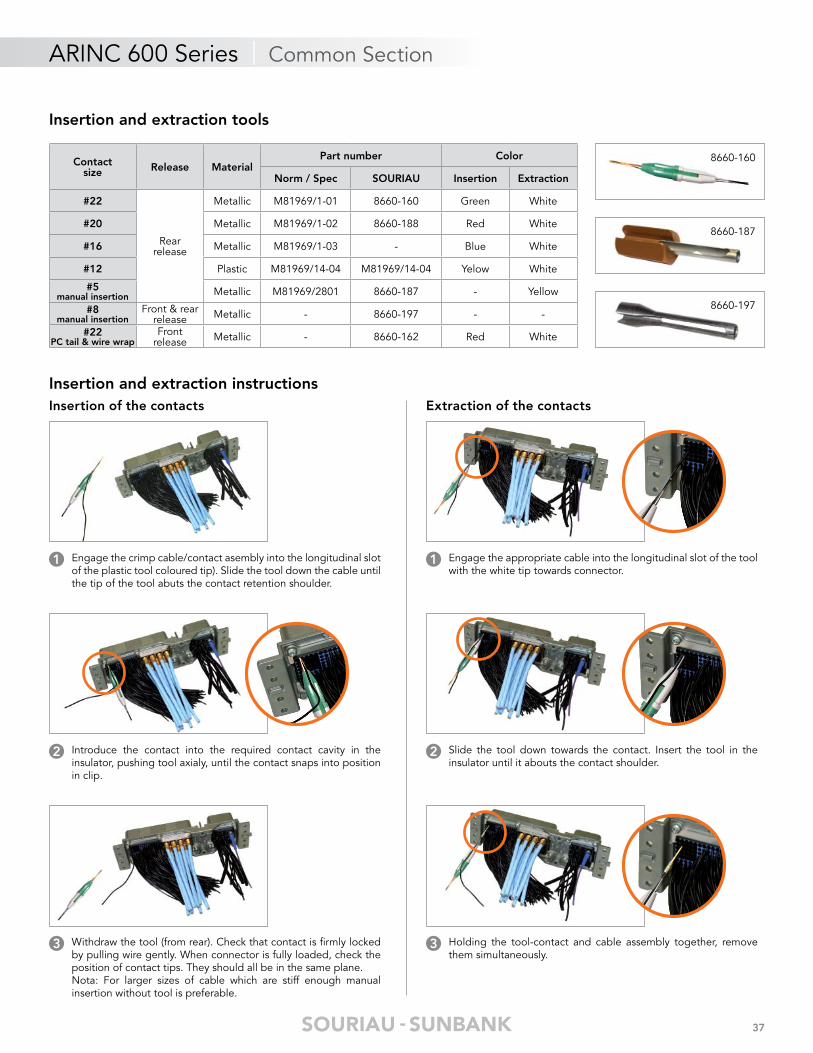
Insertion and extraction instructions
Insertion and extraction tools
8660-187
8660-197
8660-160Contactsize Release Material
Part number Color
Norm / Spec SOURIAU Insertion Extraction
#22
Rearrelease
Metallic M81969/1-01 8660-160 Green White
#20 Metallic M81969/1-02 8660-188 Red White
#16 Metallic M81969/1-03 - Blue White
#12 Plastic M81969/14-04 M81969/14-04 Yelow White
#5manual insertion Metallic M81969/2801 8660-187 - Yellow
#8manual insertion
Front & rear release Metallic - 8660-197 - -
#22PC tail & wire wrap
Frontrelease Metallic - 8660-162 Red White
Insertion of the contacts
Engage the crimp cable/contact asembly into the longitudinal slot of the plastic tool coloured tip). Slide the tool down the cable until the tip of the tool abuts the contact retention shoulder.
1
Introduce the contact into the required contact cavity in theinsulator, pushing tool axialy, until the contact snaps into position in clip.
2
Withdraw the tool (from rear). Check that contact is fi rmly locked by pulling wire gently. When connector is fully loaded, check the position of contact tips. They should all be in the same plane.Nota: For larger sizes of cable which are stiff enough manualinsertion without tool is preferable.
3
Extraction of the contacts
Engage the appropriate cable into the longitudinal slot of the tool with the white tip towards connector.
1
Slide the tool down towards the contact. Insert the tool in the insulator until it abouts the contact shoulder.
2
Holding the tool-contact and cable assembly together, remove them simultaneously.
3
38
ARINC 600 Series | Common Section
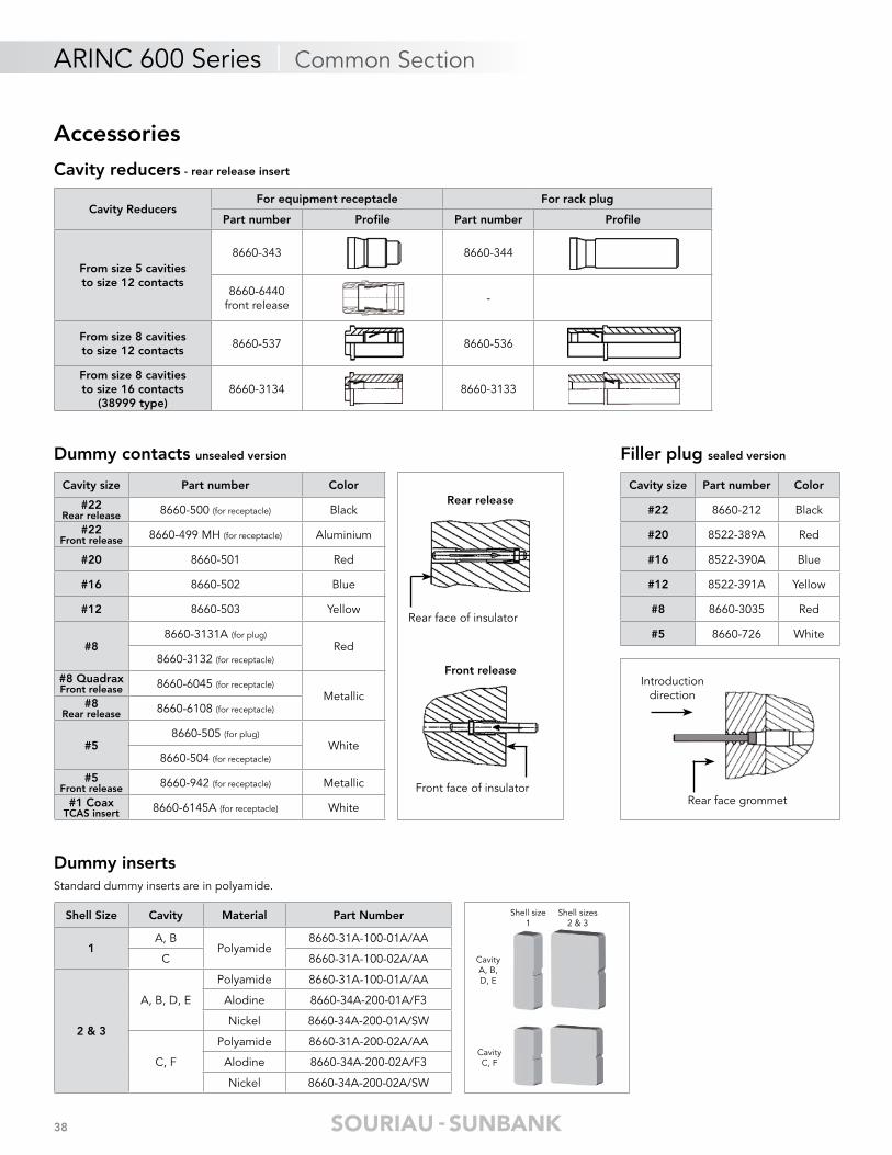
AccessoriesCavity reducers - rear release insert
Cavity ReducersFor equipment receptacle For rack plug
Part number Profi le Part number Profi le
From size 5 cavitiesto size 12 contacts
8660-343 8660-344
8660-6440front release -
From size 8 cavitiesto size 12 contacts
8660-537 8660-536
From size 8 cavitiesto size 16 contacts
(38999 type)8660-3134 8660-3133
Filler plug sealed version
Introduction direction
Rear face grommet
Cavity size Part number Color
#22 8660-212 Black
#20 8522-389A Red
#16 8522-390A Blue
#12 8522-391A Yellow
#8 8660-3035 Red
#5 8660-726 White
Dummy contacts unsealed version
Rear release
Rear face of insulator
Front release
Front face of insulator
Cavity size Part number Color
#22Rear release 8660-500 (for receptacle) Black
#22Front release 8660-499 MH (for receptacle) Aluminium
#20 8660-501 Red
#16 8660-502 Blue
#12 8660-503 Yellow
#88660-3131A (for plug)
Red8660-3132 (for receptacle)
#8 QuadraxFront release 8660-6045 (for receptacle)
Metallic#8
Rear release 8660-6108 (for receptacle)
#58660-505 (for plug)
White8660-504 (for receptacle)
#5Front release 8660-942 (for receptacle) Metallic
#1 CoaxTCAS insert 8660-6145A (for receptacle) White
Dummy insertsStandard dummy inserts are in polyamide.
Shell Size Cavity Material Part Number
1A, B
Polyamide8660-31A-100-01A/AA
C 8660-31A-100-02A/AA
2 & 3
A, B, D, E
Polyamide 8660-31A-100-01A/AA
Alodine 8660-34A-200-01A/F3
Nickel 8660-34A-200-01A/SW
C, F
Polyamide 8660-31A-200-02A/AA
Alodine 8660-34A-200-02A/F3
Nickel 8660-34A-200-02A/SW
Shell size1
Shell sizes 2 & 3
CavityC, F
CavityA, B, D, E
39
ARINC 600 Series | Common Section
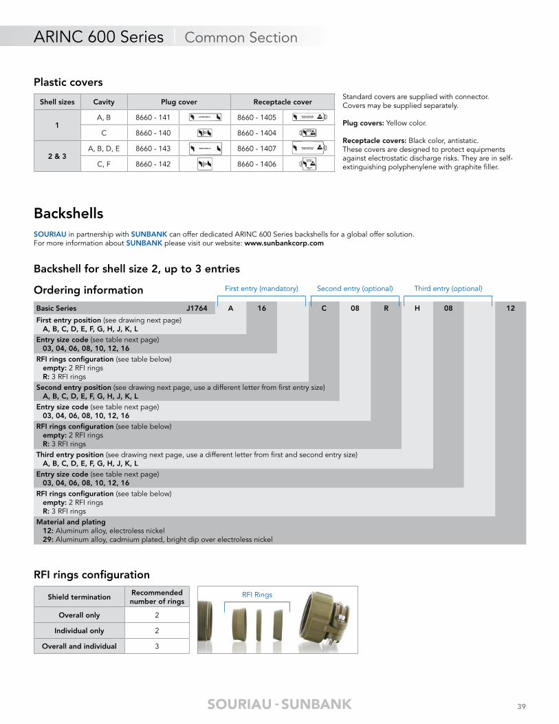
Plastic coversStandard covers are supplied with connector.Covers may be supplied separately.
Plug covers: Yellow color.
Receptacle covers: Black color, antistatic.These covers are designed to protect equipments against electrostatic discharge risks. They are in self-extinguishing polyphenylene with graphite fi ller.
Shell sizes Cavity Plug cover Receptacle cover
1A, B 8660 - 141 8660 - 1405
C 8660 - 140 8660 - 1404
2 & 3A, B, D, E 8660 - 143 8660 - 1407
C, F 8660 - 142 8660 - 1406
BackshellsSOURIAU in partnership with SUNBANK can offer dedicated ARINC 600 Series backshells for a global offer solution. For more information about SUNBANK please visit our website: www.sunbankcorp.com
Backshell for shell size 2, up to 3 entries
Ordering information
Basic Series J1764 A 16 C 08 R H 08 12
First entry position (see drawing next page) A, B, C, D, E, F, G, H, J, K, LEntry size code (see table next page) 03, 04, 06, 08, 10, 12, 16RFI rings confi guration (see table below) empty: 2 RFI rings R: 3 RFI ringsSecond entry position (see drawing next page, use a different letter from fi rst entry size) A, B, C, D, E, F, G, H, J, K, LEntry size code (see table next page) 03, 04, 06, 08, 10, 12, 16RFI rings confi guration (see table below) empty: 2 RFI rings R: 3 RFI ringsThird entry position (see drawing next page, use a different letter from fi rst and second entry size) A, B, C, D, E, F, G, H, J, K, LEntry size code (see table next page) 03, 04, 06, 08, 10, 12, 16RFI rings confi guration (see table below) empty: 2 RFI rings R: 3 RFI ringsMaterial and plating 12: Aluminum alloy, electroless nickel 29: Aluminum alloy, cadmium plated, bright dip over electroless nickel
First entry (mandatory) Second entry (optional) Third entry (optional)
RFI rings confi guration
RFI RingsShield terminationRecommended number of rings
Overall only 2
Individual only 2
Overall and individual 3

40
ARINC 600 Series | Common Section
Dimensions
Note: All dimensions are in millimeters/inches (mm/inch)
Entrysizecode
Millimeters Inches
A Max B MaxC (cable range)
A Max B MaxC (cable range)
Min Max Min Max
03 19.30 21.44 3.99 6.35 0.76 0.844 0.157 0.25
04 19.30 23.01 4.75 7.92 0.76 0.906 0.187 0.312
06 19.30 27.76 7.14 11.10 0.76 1.093 0.281 0.437
08 19.30 30.15 8.74 14.27 0.76 1.187 0.344 0.562
10 19.30 32.54 9.53 15.88 0.76 1.281 0.375 0.625
12 19.30 38.10 11.13 19.05 0.76 1.50 0.438 0.75
16 27.25 43.66 14.27 23.83 1.073 1.719 0.562 0.938
Entry size code
Entry A
Entry B
Entry C
Entry K
Entry J
Entry H
Entry D
Entry E
Entry F
Entry G
Entry L
A
BC
Three ringsexample
Two ringsexample
Ø 3.175 / 0.125
45.47 / 1.79
64.52 / 2.54
63.50±0.79 / 2.50±0.031
1.65 / 0.065
1.65 / 0.065
139.
70±
0.25
/ 5
.50±
0.01
41
ARINC 600 Series | Common Section
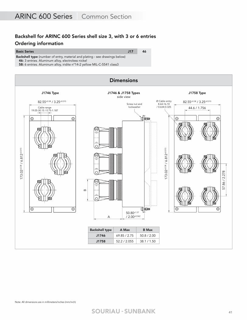
Dimensions
Note: All dimensions are in millimeters/inches (mm/inch)
Backshell for ARINC 600 Series shell size 3, with 3 or 6 entriesOrdering information
Basic Series J17 46
Backshell type (number of entry, material and plating - see drawings below) 46: 3 entries. Aluminum alloy, electroless nickel 58: 6 entries. Aluminum alloy, iridite n°14-2 yellow MIL-C-5541 class3
Backshell type A Max B Max
J1746 69.85 / 2.75 50.8 / 2.00
J1758 52.2 / 2.055 38.1 / 1.50
J1746 Type J1758 TypeJ1746 & J1758 Typesside view
50.80±1.57
/ 2.00±0.062A
B
Screw nut and lockwasher
Ø Cable entry8.64-16.10
/ 0.634-0.325
82.55±0.38 / 3.25±0.015
Cable range19.05-30.15 / 0.75-1.187
173.
02±
0.38
/ 6
.812
±0.
015
173.
02±
0.38
/ 6
.812
±0.
015
82.55±0.38 / 3.25±0.015
44.6 / 1.756
57.8
6 /
2.27
8

AR
INC
60
0 S
ER
IES
© 2017 SOURIAU - SOURIAU is a registered trademark
Range ExtensionARINC 600 Series
Custom product ...................................................................................................... 44
microComp® Series ................................................................................................ 44
Nafi 1 & 2 Series ..................................................................................................... 45
D-Subminiature Series ............................................................................................ 45
Box mount interconnect solutions .......................................................................... 46

44
ARINC 600 Series | Range Extension
Product range extension
micromicroCompComp®® Series Series
To respond to miniaturization and weight saving trends in aeronautical and defense applications SOURIAU has developed an innovative highdensity connector range.
Very light & high density: . Shell in composite (or aluminum). . Up to 66% lighter than HD D-Sub. . Very high density up to 40% smaller than HD D-Sub.
Excellent features: . With crimp removable contacts for wire AWG 24 to 28. . Temperature up to 175°C. . High vibration and shock withstanding. . Standard MIL-STD 83513 accessories. . Compatible with high speed data rates (Gigabit Ethernet...).
Quick connect version: . MCQL microComp® Quick Latch.
See «microComp® Series - Miniature High Density» datasheet on www.souriau.com
Custom Products
SOURIAU is offering a high developmentcapability for your specifi c needs
• Specifi c monocavity - available for any Souriau insulators (pictures: Q11 and 150 points layouts)
• Space saving solution - With right angle cable orientator - 35mm outing length
• Specifi c machined shells for customized needs
1
2
3
consult us
1
2
3

45
Product range extension
ARINC 600 Series | Range Extension
D-Subminiature SeriesD-Subminiature Series
Connectors designed to ensure the connection fonction in all applications where weight and dimension are very important. Especially used as Input/Output connectors in interface fonctions. Compliant with MIL/HE/NFC.
Space saving: . Miniature design.
A wide range: . 8630, SMA, 8635, hermetic, feedthrough.
Removable crimp contacts: . Size 20 for the Mark III. . Size 22D for the High Density Series. . PC tail version available.
Versatility: . Easy to handle.
See «D-Subminiature Series, Rectangular Connectors» catalog on www.souriau.com
Nafi 1 & 2 Series
PCB interconnection according to MIL-C 28754. Board-mounted connectors used as interface between daughter-boards and back planes or between two adjacent daughter-boards.
High vibration resistance: . Perfectly adapted to military PCB connection.
High Density: . 2.54 pitch (NAFI 1). . 1.27 pitch (NAFI 2). . Up to 556 contacts.
Large contacts offer: . Straight & angle contacts. . Straight PC tail with flex connection. . Press fit contacts.

46
Box MountInterconnect Solutions
Box Interconnect Solutions: Inside/Outside.Anything you need - we can do !
PCB terminations: . with many lengths and different types of plating.
Shape of connector can be adapted: . to meet the board application as double flange receptacles.
Receptacles with short shell: . to minimize space inside the box.
Any customized design: . to make box mount easier when space is a constraint.
Blindmate/hermetic/thin panel assembly solutions...
See «Box Mount Interconnect Solutions» catalog on www.souriau.com
Product range extension
ARINC 600 Series | Range Extension


Your local contact
Our contribution to environmental protection:This catalog is printed on PEFC certifi ed paperAdvancement of sustainablewood cultivation. www.pefc.org
WC
AA
RIN
C60
0WU
SEN
04 ©
Cop
yrig
ht S
OU
RIA
U M
ar 2
017
- SO
URI
AU
is a
reg
iste
red
tra
dem
ark
All
info
rmat
ion
in t
his
doc
umen
t p
rese
nts
only
gen
eral
par
ticul
ars
and
sha
ll no
t fo
rm p
art
of a
ny c
ontr
act.
All
right
s re
serv
ed t
o SO
URI
AU
for
chan
ges
with
out
prio
r no
tifi c
atio
n or
pub
lic a
nnou
ncem
ent.
Any
dup
licat
ion
is p
rohi
bite
d, u
nles
s ap
pro
ved
in w
ritin
g.
10-31-1299
Reliable People, Reliable Solutions
www.esterline-connection-technologies.comcontactmilaero@souriau.com