
ARI Deployment Guide for Cisco Unified Intelligent Contact … · Figure 14: Setup: ARS PIM...
73
ARI Deployment Guide for Cisco Unified Intelligent Contact Management Enterprise & Hosted Release 7.5(1) July 2008 Americas Headquarters Cisco Systems, Inc. 170 West Tasman Drive San Jose, CA 95134-1706 USA http://www.cisco.com Tel: 408 526-4000 800 553-NETS (6387) Fax: 408 527-0833
Transcript of ARI Deployment Guide for Cisco Unified Intelligent Contact … · Figure 14: Setup: ARS PIM...
ARI Deployment Guide
for Cisco Unified Intelligent Contact Management
Enterprise & HostedRelease 7.5(1)
July 2008
Americas Headquarters
Cisco Systems, Inc.
170 West Tasman Drive
San Jose, CA 95134-1706
USA
http://www.cisco.com
Tel: 408 526-4000
800 553-NETS (6387)
Fax: 408 527-0833

THE SPECIFICATIONS AND INFORMATION REGARDING THE PRODUCTS IN THIS MANUAL ARE SUBJECT TO CHANGE WITHOUT NOTICE.ALL STATEMENTS, INFORMATION, AND RECOMMENDATIONS IN THIS MANUAL ARE BELIEVED TO BE ACCURATE BUT ARE PRESENTEDWITHOUT WARRANTY OF ANY KIND, EXPRESS OR IMPLIED. USERS MUST TAKE FULL RESPONSIBILITY FOR THEIR APPLICATION OFANY PRODUCTS.THE SOFTWARE LICENSE AND LIMITED WARRANTY FOR THE ACCOMPANYING PRODUCT ARE SET FORTH IN THE INFORMATION PACKETTHAT SHIPPED WITH THE PRODUCT AND ARE INCORPORATED HEREIN BY THIS REFERENCE. IF YOU ARE UNABLE TO LOCATE THESOFTWARE LICENSE OR LIMITED WARRANTY, CONTACT YOUR CISCO REPRESENTATIVE FOR A COPY.The Cisco implementation of TCP header compression is an adaptation of a program developed by the University of California, Berkeley (UCB) aspart of UCBs public domain version of the UNIX operating system. All rights reserved. Copyright © 1981, Regents of the University ofCalifornia.NOTWITHSTANDING ANY OTHER WARRANTY HEREIN, ALL DOCUMENT FILES AND SOFTWARE OF THESE SUPPLIERS ARE PROVIDED"AS IS" WITH ALL FAULTS. CISCO AND THE ABOVE-NAMED SUPPLIERS DISCLAIM ALL WARRANTIES, EXPRESSED OR IMPLIED, INCLUDING,WITHOUT LIMITATION, THOSE OF MERCHANTABILITY, FITNESS FOR A PARTICULAR PURPOSE AND NONINFRINGEMENT OR ARISINGFROM A COURSE OF DEALING, USAGE, OR TRADE PRACTICE.IN NO EVENT SHALL CISCO OR ITS SUPPLIERS BE LIABLE FOR ANY INDIRECT, SPECIAL, CONSEQUENTIAL, OR INCIDENTAL DAMAGES,INCLUDING, WITHOUT LIMITATION, LOST PROFITS OR LOSS OR DAMAGE TO DATA ARISING OUT OF THE USE OR INABILITY TO USETHIS MANUAL, EVEN IF CISCO OR ITS SUPPLIERS HAVE BEEN ADVISED OF THE POSSIBILITY OF SUCH DAMAGES.CCDE, CCENT, Cisco Eos, Cisco Lumin, Cisco Nexus, Cisco StadiumVision, Cisco TelePresence, the Cisco logo, DCE, and Welcome to the HumanNetwork are trademarks; Changing the Way We Work, Live, Play, and Learn and Cisco Store are service marks; and Access Registrar, Aironet,AsyncOS, Bringing the Meeting To You, Catalyst, CCDA, CCDP, CCIE, CCIP, CCNA, CCNP, CCSP, CCVP, Cisco, the Cisco Certified InternetworkExpert logo, Cisco IOS, Cisco Press, Cisco Systems, Cisco Systems Capital, the Cisco Systems logo, Cisco Unity, Collaboration Without Limitation,EtherFast, EtherSwitch, Event Center, Fast Step, Follow Me Browsing, FormShare, GigaDrive, HomeLink, Internet Quotient, IOS, iPhone, iQ Expertise,the iQ logo, iQ Net Readiness Scorecard, iQuick Study, IronPort, the IronPort logo, LightStream, Linksys, MediaTone, MeetingPlace, MeetingPlaceChime Sound, MGX, Networkers, Networking Academy, Network Registrar, PCNow, PIX, PowerPanels, ProConnect, ScriptShare, SenderBase,SMARTnet, Spectrum Expert, StackWise, The Fastest Way to Increase Your Internet Quotient, TransPath, WebEx, and the WebEx logo are registeredtrademarks of Cisco Systems, Inc. and/or its affiliates in the United States and certain other countries.All other trademarks mentioned in this document or Website are the property of their respective owners. The use of the word partner does not implya partnership relationship between Cisco and any other company. (0807R)Any Internet Protocol (IP) addresses used in this document are not intended to be actual addresses. Any examples, command display output, andfigures included in the document are shown for illustrative purposes only. Any use of actual IP addresses in illustrative content is unintentional andcoincidental.Copyright @ 2008 Cisco Systems, Inc. All rights reserved.

Table of Contents
Preface ...........................................................................................................................................................1Purpose .....................................................................................................................................................1Audience ....................................................................................................................................................2Organization ..............................................................................................................................................2Related Documentation .............................................................................................................................2Conventions................................................................................................................................................3Obtaining Documentation, Obtaining Support, and Security Guidelines....................................................4
1. About ARI Deployment................................................................................................................................5Supported ACDs in this Release of the ARI Deployment...........................................................................6Advantages of the ARI Deployment............................................................................................................6Who Might Chose to Implement the ARI Deployment?..............................................................................7Supported Features....................................................................................................................................7Unsupported Features................................................................................................................................8
2. Architecture and Models for the ARI Deployment.......................................................................................9Overview of Architecture and Core Components.......................................................................................9
Platform and Network............................................................................................................................9The Central Controller (Router and Logger)........................................................................................10The Peripheral Gateway (PG)..............................................................................................................11The ARS PG........................................................................................................................................12The Admin Workstation (AW)...............................................................................................................14The CTI Server....................................................................................................................................14CTI OS.................................................................................................................................................15The ACD/PBX......................................................................................................................................15The Voice Response Unit (VRU)..........................................................................................................15
Examples of Deployment Models for the ARI Solution.............................................................................18
3. Installation and Configuration for the ARI Deployment.............................................................................21Installation................................................................................................................................................21
About the Server Where You Install ARS PG.......................................................................................21Preparing a Server for the ARS PG.....................................................................................................22Installing the ARS PG on the Server...................................................................................................24Installing CTI OS Server on the ARS PG Server Machine..................................................................29Installing the Agent and IPCC Supervisor Desktops...........................................................................30
Configuration............................................................................................................................................31About ACD/PBX Configuration............................................................................................................32About Configuration Manager..............................................................................................................32Configuring a Network VRU.................................................................................................................33Configuring Agent Desk Settings.........................................................................................................34Configuring the ARS PG......................................................................................................................36Configuring the ARS PG Peripheral: Peripheral Tab............................................................................37Configuring the ARS PG Peripheral: Advanced Tab............................................................................39Configuring the ARS PG Peripheral: Agent Distribution and Skill Group Mask Tabs...........................40Configuring the ARS PG Peripheral: Routing Client Tab......................................................................40Configuring the ARS PG Peripheral: Default Route Tab......................................................................41Configuring the ARS PG Peripheral: Peripheral Monitor Tab...............................................................42Configuring Agent Targeting Rules......................................................................................................44Configuring for Reporting in an ARI Deployment.................................................................................45Notes on Other Configuration..............................................................................................................46
ARI Deployment Guide for Cisco Unified Intelligent Contact Management Enterprise & Hosted Release 7.5(1)
i

4. Queuing, Routing, and Reporting with an ARI Deployment......................................................................51Queuing....................................................................................................................................................51Routing.....................................................................................................................................................52
Device Targets and Agent Targeting Rules..........................................................................................53Pre-Routing..........................................................................................................................................54Post Routing........................................................................................................................................54Translation Routing..............................................................................................................................54
Scripting...................................................................................................................................................55Using WebView with your ARI Deployment..............................................................................................56
5. Desktops and Call Control........................................................................................................................57About Computer Telephony Integration....................................................................................................57Agent Phones...........................................................................................................................................57
Softphone............................................................................................................................................58Hard Phones........................................................................................................................................58Synchronization...................................................................................................................................59
Desktops and Call Control........................................................................................................................59The Agent Desktop..............................................................................................................................60The Supervisor Desktop......................................................................................................................60Desktop Differences.............................................................................................................................61
Agent States.............................................................................................................................................61Changing Agent State from the Desktop.............................................................................................62Notes on Agent State Transitions.........................................................................................................62
Index .............................................................................................................................................................65
ARI Deployment Guide for Cisco Unified Intelligent Contact Management Enterprise & Hosted Release 7.5(1)
ii

List of Figures
Figure 1: The ARS Gateway............................................................................................................................................14
Figure 2: External (Network) VRU..................................................................................................................................16
Figure 3: Virtual (embedded) VRU..................................................................................................................................17
Figure 4: ARS PG Added to Existing System.................................................................................................................18
Figure 5: ARS PG Replaces TDM PG.............................................................................................................................19
Figure 6: New Deployment with all ARS PGs................................................................................................................19
Figure 7: Server for the ARS PG.....................................................................................................................................22
Figure 8: Logical Controller ID.......................................................................................................................................24
Figure 9: Peripheral ID....................................................................................................................................................24
Figure 10: Setup: Select PG Component.........................................................................................................................25
Figure 11: Setup: Select ARS Client Type.......................................................................................................................25
Figure 12: Peripheral Gateway Component Properties...................................................................................................26
Figure 13: Setup: Add PIM popup...................................................................................................................................26
Figure 14: Setup: ARS PIM Configuration dialog box...................................................................................................27
Figure 15: Setup: Peripheral Gateway Component Properties........................................................................................28
Figure 16: Setup: Device Management Protocol Properties............................................................................................28
Figure 17: Setup: Peripheral Gateway Network Interfaces.............................................................................................29
Figure 18: Setup: Check Setup Information ...................................................................................................................29
Figure 19: CTI OS Peripheral Identifier Screen..............................................................................................................30
Figure 20: Configuration Manager..................................................................................................................................33
Figure 21: Configuring Network VRU............................................................................................................................34
Figure 22: Configuring Agent Desk Settings...................................................................................................................36
Figure 23: Configuring the PG........................................................................................................................................37
Figure 24: Configuring the PG Peripheral.......................................................................................................................37
Figure 25: Configuring the PG Peripheral: Peripheral Tab.............................................................................................38
Figure 26: Configuring the PG Peripheral: Advanced Tab..............................................................................................39
Figure 27: Configuring the PG Peripheral: Agent Distribution Tab................................................................................40
Figure 28: Configuring the PG Peripheral: Routing Client Tab......................................................................................41
Figure 29: Configuring the PG Peripheral: Default Route Tab.......................................................................................42
Figure 30: Configuring the PG Peripheral: Peripheral Monitor Tab...............................................................................43
Figure 31: Configuring Agent Targeting Rules...............................................................................................................45
Figure 32: Select the ARS PG when Configuring...........................................................................................................46
Figure 33: Selection when Configuring Skill Groups.....................................................................................................48
ARI Deployment Guide for Cisco Unified Intelligent Contact Management Enterprise & Hosted Release 7.5(1)
iii

Figure 34: WebView Template Selection.........................................................................................................................56
ARI Deployment Guide for Cisco Unified Intelligent Contact Management Enterprise & Hosted Release 7.5(1)
iv

Preface
Purpose
This guide provides information to help you understand, install, and configure the Agent RoutingInterface (ARI) deployment.
The ARI deployment is supported for Cisco Unified Intelligent Contact Management Enterprise(Unified ICME) and Cisco Unified Intelligent Contact Management Hosted (Unified ICMH).
A note about new Cisco product names
• Cisco ICM Enterprise Edition is renamed Cisco Unified Intelligent Contact ManagementEnterprise (abbreviated as Unified ICME). Cisco ICM Hosted Edition is renamed CiscoUnified Intelligent Contact Management Hosted (abbreviated as Unified ICMH).
• Cisco IPCC Enterprise Edition and Cisco IPCC Hosted Edition are renamed Cisco UnifiedContact Center Enterprise (abbreviated as Unified CCE) and Cisco Unified Contact CenterHosted (abbreviated as Unified CCH), respectively.
• Cisco CallManager is renamed Cisco Unified Communications Manager.
The new product names are being introduced in phases. In the 7.2(1) release, the new namesrefer to the product as a whole. They are not yet used for functions and utilities in the userinterface. For example, the ICM Admin Workstation is not yet renamed and is still referred toas the ICM and not the Unified ICM Admin Workstation.
Although this guide refers to the product as a whole by its new name, it refers to componentsand utilities by the names that appear in the user interface.
ARI Deployment Guide for Cisco Unified Intelligent Contact Management Enterprise & Hosted Release 7.5(1)
1

Audience
This document is intended for anyone who plans to install, configure, and maintain an ARIdeployment by adding an Agent Routing Service Peripheral Gateway (an ARS PG) to theirUnified ICM Enterprise system.
Organization
In addition to this Preface, this guide contains five chapters and an index.
Chapter 1 (page 5) explains the concept and the advantages of an ARI deployment and listssupported and unsupported features.
Chapter 2 (page 9) gives an overview of the Unified ICM architecture and how an ARIdeployment fits into that architecture.
Chapter 3 (page 21) covers installation for an ARI Deployment and what parameters to set forARI in Configuration Manager.
Chapter 4 (page 51) discusses Queuing, Routing, and Reporting with an ARI Deployment.
Chapter 5 (page 57) explains agent and supervisor desktops and call control.
Related Documentation
CTI OS Agent Desktop User Guide for Cisco Unified ICM/CC Enterprise & Hosted
CTI OS Developer's Guide
CTI OS Supervisor Desktop User Guide
ICM Installation Guide for Cisco ICM Enterprise Edition
Hardware and System Software Specification (Bill of Materials) located on cisco.com (http://www.cisco.com/en/US/products/sw/custcosw/ps1001/products_user_guide_list.html)
Installation Guide Cisco ICM/IPCC Enterprise & Hosted Editions Release 7.2(1)
IPCC Installation and Configuration Guide for Cisco IPCC Enterprise Edition
Reporting Guide for Cisco Unified ICM Enterprise & Hosted
Reporting Guide for Cisco IPCC Enterprise & Hosted Editions
Staging Guide for Cisco ICM/IPCC Enterprise & Hosted Editions
ARI Deployment Guide for Cisco Unified Intelligent Contact Management Enterprise & Hosted Release 7.5(1)
2
Preface
Audience

System Manager Guide Supplement for Avaya ARS PG
Conventions
This manual uses the following conventions:
DescriptionConvention
Boldface font is used to indicate commands,such as user entries, keys, buttons, and folderand submenu names. For example:
boldface font
• Choose Edit > Find.
• Click Finish.
Italic font is used to indicate the following:italic font
• To introduce a new term. Example: A skillgroup is a collection of agents who sharesimilar skills.
• For emphasis. Example: Do not use thenumerical naming convention.
• A syntax value that the user must replace.Example: IF (condition, true-value,false-value)
• A book title. Example: See the Cisco CRSInstallation Guide.
Window font, such as Courier, is used for thefollowing:
window font
• Text as it appears in code or that the windowdisplays. Example: <html><title>CiscoSystems,Inc. </title></html>
Angle brackets are used to indicate thefollowing:
< >
• For arguments where the context does notallow italic, such as ASCII output.
• A character string that the user enters butthat does not appear on the window such asa password.
ARI Deployment Guide for Cisco Unified Intelligent Contact Management Enterprise & Hosted Release 7.5(1)
3
Preface
Conventions

Obtaining Documentation, Obtaining Support, and Security Guidelines
For information on obtaining documentation, obtaining support, providing documentationfeedback, security guidelines, and also recommended aliases and general Cisco documents, seethe monthly What's New in Cisco Product Documentation, which also lists all new and revisedCisco technical documentation, at:
http://www.cisco.com/en/US/docs/general/whatsnew/whatsnew.html
ARI Deployment Guide for Cisco Unified Intelligent Contact Management Enterprise & Hosted Release 7.5(1)
4
Preface
Obtaining Documentation, Obtaining Support, and Security Guidelines
About ARI DeploymentAgent Routing Integration (ARI) deployment allows the Unified ICM software to select agentsand to route calls directly to them.
ARI is implemented by using an ARS PG (page 12).
Before ARI was introduced, the method by which Unified ICM interfaced with an AutomaticCall Distributor (ACD) was through a customized TDM PG designed specifically for that ACD.Reporting management, agent skill mapping, and routing decisions remained under control ofthe ACD. It was the role of the ACD (and not Unified ICM), to select the agent. Although usingTDM-specific PGs remains a viable deployment, the option of using an ARS PG adds flexibilityto the Unified ICM environment.
In an ARI deployment with an ARS PG, traditional "ACD functions" move to the Unified ICM.The role of the ACD changes from a TDM ACD to an ACD/PBX that serves as the telephoneswitching system. In this role, the ACD/PBX provides connections for agent phones and connectsa call to an agent, as directed by the Unified ICM Router.
As part of Unified ICM, the ARI deployment can be implemented in a single-site environmentor integrated into a multisite contact-center enterprise.
In this guide, the term ARI deployment refers to Unified ICME systems where one or more ARSPGs have been added to, or have replaced, one or more TDM PGs. An ARI deployment mightalso be a Unified ICME system that uses ARS PGs only.
This chapter contains the following topics:
• Supported ACDs in this Release of the ARI Deployment, page 6• Advantages of the ARI Deployment, page 6• Who Might Chose to Implement the ARI Deployment?, page 7• Supported Features, page 7• Unsupported Features, page 8
ARI Deployment Guide for Cisco Unified Intelligent Contact Management Enterprise & Hosted Release 7.5(1)
5
Chapter 1

Supported ACDs in this Release of the ARI Deployment
Each ARS PG supports only one ACD/PBX peripheral.
The ACD/PBX supported in Release 7.2(1) is the Avaya Communications Manager 3.0 or 3.1.2
with AES Server.1
Advantages of the ARI Deployment
These are some advantages of deploying ARI with an ARS PG:
• Call queuing is controlled by Service Control Interface (SCI)-managed queue points. Thisis the case whether the VRU is at the network level or is premise-based on the ACD/PBX.
Queuing thus occurs such that Unified ICM retains control of the call. This is a distinctadvantage over traditional, ACD-controlled queuing. The call does not 'get stuck at' the ACD,and Unified ICM does not lose control of the call. The call remains available for enterpriserouting depending on agent availability and collected information. See Queuing (page 51).
• Intelligent call routing through a single platform and the ability to route a call to aspecific agent
Because the ARS PG hands control for routing to the Unified ICM, you can rely on a singlerouting platform. When the ICM connects to traditional TDM PGs, the call is routed to askill group at the ACD, not directly to the agent. With an ARS PG, the ICM can route to anagent, by login ID or extension.
• Improved, consolidated reporting
You can use WebView's reporting categories to monitor contact center agent performance,customer experience, and operational effectiveness—rather than running some reports fromthe ACD (such as ACD agent reports) and running other reports from WebView. See UsingWebView with your ARI Deployment (page 56).
• Transition to an IP Call Center
Introducing an ARS PG is an intermediate solution and a migration path to what can eventuallybecome a full IP solution.
• Retention of existing ACD Hardware
If you already deploy an ACD that interfaces to Unified ICM by a TDM PG (for example,if you already have an Avaya Communications Manager 3.1.2), there is no need to removeor replace the switch hardware. With the ARS PG, you can use existing hardware (the legacyACD), and connect to it with an ARS PG rather than a TDM PG.
1) Former names for the Avaya Communications Manager were the Avaya DEFINTY, the G3, and the Avaya MultiVantage.
ARI Deployment Guide for Cisco Unified Intelligent Contact Management Enterprise & Hosted Release 7.5(1)
6
Chapter 1: About ARI Deployment
Supported ACDs in this Release of the ARI Deployment

• Additional supervisory features
Connection with the ARS PG extends the functionality of the agent and supervisor desktops.For example, supervisor barge-in and intercept—formerly offered only in an Cisco UnifiedContact Center (formerly named IPCC) environment—become available in Unified ICM.See The Supervisor Desktop (page 60).
Who Might Chose to Implement the ARI Deployment?
Possible implementation scenarios include:
• Unified ICME customers who have legacy TDM PG connections to ACDs in place and whowant to add an ARS PG and a supported ACD/PBX (page 6) to their deployment.
• Unified ICME customers who choose to replace their current TDM PG with the ARS PG,in effect handing control over to ICM and 'dumbing down' the ACD so that it serves as anACD/PBX.
• New Unified ICME customers who plan to interface with ARS PGs only, rather than withTDM PGs.
See also Examples of Deployment Models for the ARI Solution (page 18)
Supported Features
These features are supported for the ARI solution:
» Agent Reskilling by supervisors
» Ability to allow mutually exclusive or concurrent use of hard phones and Cisco softphones
» Ability to implement and configure Agent Targeting Rules (page 44)
» Cradle-to-grave tracking (the ability to track a call from start to finish, independent of transfers,overflows, or diversions that occur during the life of the call)
» Duplexing, for a fully redundant and fault-tolerant solution
» Interactive voice response (IVR) integration
» Interfaces for CTI-type integrations (includes third-party call control)
» Monitoring of agent states
» Monitoring of call data and call states
» Pre-routing, post-routing, and translation routing
ARI Deployment Guide for Cisco Unified Intelligent Contact Management Enterprise & Hosted Release 7.5(1)
7
Chapter 1: About ARI Deployment
Who Might Chose to Implement the ARI Deployment?

» Reporting (a full set of ACD reports, including Agent-level reporting)
» Scalability, as tied to the capacity for CTI OS servers that co-reside with Agent PG serversfor IPCC Enterprise, New Deployments/Technology Refresh. See the Hardware and SystemSoftware Specification (Bill of Materials). Click here for the link to this document. (page 2)
» Supervisory barge-in and intercept functions
» Unified ICM based routing for agents connected to the ACD/PBX
Unsupported Features
These features are not currently supported for ARI:
» ACD Queues
» Agent Desk Settings for AutoRecord on Emergency
» Agent Desk Settings for Outbound Access
» Blended Collaboration (multi-media integration)
» Call recording
» Call rerouting based on non-answer (RONA)
» ICM Universal Queue
» Manual entry of hardphone access codes
» Outbound Option
» Peripheral Service Level reporting
» Remote Agent, Mobile Agent
» Silent Monitoring on the CTI OS Supervisor desktop
» Sub-skill groups
» Service Bureau Configuration with shared resources
» Trunk and Trunk Group reporting
ARI Deployment Guide for Cisco Unified Intelligent Contact Management Enterprise & Hosted Release 7.5(1)
8
Chapter 1: About ARI Deployment
Unsupported Features

Architecture and Models for the ARI DeploymentThis chapter contains the following topics:
• Overview of Architecture and Core Components, page 9• Examples of Deployment Models for the ARI Solution, page 18
Overview of Architecture and Core Components
What follows is a summary of the components that comprise a Unified ICM system, noting howthey do—or do not—differ for an ARI deployment.
For details on these components, refer to the Preinstallation Planning Guide for Cisco ICMEnterprise Edition and the ICM Installation Guide for Cisco ICM Enterprise Edition.
Platform and Network
The operating system, domain requirement, network interface, server platforms, and faulttolerance are described in the topic that follows.
Operating System
Unified ICM requires a Microsoft Windows operating system. Refer to the Hardware and SystemSoftware Specification (Bill of Materials) (page 2) for Operating System requirements.
Active Directory
Unified ICM software uses Windows Active Directory to control users' access rights to performsetup, configuration, and reporting tasks.
ARI Deployment Guide for Cisco Unified Intelligent Contact Management Enterprise & Hosted Release 7.5(1)
9
Chapter 2
You can install Unified ICM software in an existing Windows domain (including the corporatedomain) and control access to ICM functions using the Active Directory functionality yournetwork already supports.
You must have added the Cisco Root Organizational Unit and at least one Facility OrganizationalUnit with one Instance Organizational Unit.
See the Staging Guide for Cisco ICM/IPCC Enterprise & Hosted Editions for details on ActiveDirectory configuration and other network configuration requirements.
Network Interface
The ACD/PBX is typically connected to the telephone network by T1 or E1 lines.
Carrier networks offer services to deliver the following information about an incoming call bymeans of an intelligent incoming trunk (for example. Primary Rate Interface):
• Calling Line ID (CLID),
• Directory Number Identification Service (DNIS),
• Called Number
• Automatic Number ID (ANI).
Server Platforms
Unified ICM components (including the ARS PG Server) are supported only on Cisco MCS orMCS-equivalent servers.
See the Hardware and System Software Specification (Bill of Materials) (page 2) for furtherspecifics on hardware requirements, including recommended platform sizing guidelines basedon the types of available hardware systems.
Fault Tolerance
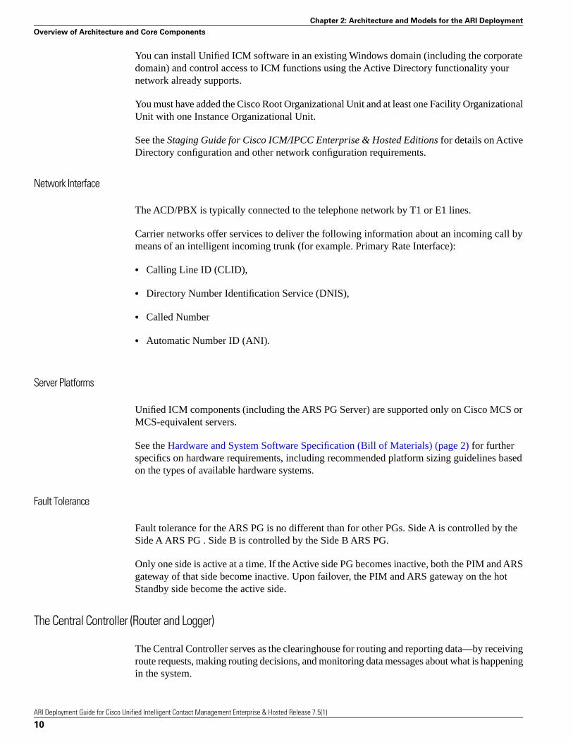
Fault tolerance for the ARS PG is no different than for other PGs. Side A is controlled by theSide A ARS PG . Side B is controlled by the Side B ARS PG.
Only one side is active at a time. If the Active side PG becomes inactive, both the PIM and ARSgateway of that side become inactive. Upon failover, the PIM and ARS gateway on the hotStandby side become the active side.
The Central Controller (Router and Logger)
The Central Controller serves as the clearinghouse for routing and reporting data—by receivingroute requests, making routing decisions, and monitoring data messages about what is happeningin the system.
ARI Deployment Guide for Cisco Unified Intelligent Contact Management Enterprise & Hosted Release 7.5(1)
10
Chapter 2: Architecture and Models for the ARI Deployment
Overview of Architecture and Core Components

The Central Controller is installed on one or more servers and comprises three major components:the CallRouter (Router), the Logger, and the Central Database.
• CallRouter (Router)
The Router receives notification from a Routing Client, such as a Network Interface Controlleror a Peripheral Gateways (PGs) (page 11), that a call is in need of some form of routing. Itthen executes a user-defined script that specifies how the Routing Client is to handle the call.
The Router also receives messages from the PGs about agent and system status events in thenetwork. Awareness of the current status of these resources is essential to the routing scripts.
The Router immediately forwards this data directly to the Admin Workstations so that it isavailable to appear in reports. The Router also writes records to the Central Database on theLogger.
• Logger and Central Database
The Logger receives data from the Router (such as detail messages about calls and summarymessages that have been computed by the Peripheral Gateways) and serves as the interfacebetween the Router and the SQL Server database manager.
The Central Database serves as a buffer where data is committed to quickly support theperformance of the Router. The Central Database stores configuration data, as entered andchanged on the Admin Workstation; routing scripts, also as entered and changed on theAdmin Workstation; summary historical data passed from the Router; and call detail data.
FOR AN ARI DEPLOYMENT, the role of the Central Controller remains exactly as for atraditional Unified ICME environment.
The Peripheral Gateway (PG)
A peripheral is a device—such as an ACD—that receives calls that have been routed by theUnified ICM Central Controller.
Agents are grouped by peripheral for reporting, call handling, and other administrative purposes.
A Peripheral Gateway (PG) is a monitoring node through which the Unified ICM CentralController communicates directly with a peripheral. The PG monitors status information fromthe peripheral and forwards that information to the Central Controller. The PG sends routingrequests to the Central Controller and receives routing information in return. The term PG refersto both a physical hardware platform (server) and the logical software processes that run on it.
Unified ICM software has unique PGs for each device it supports, including switch-specificTDM PGs that connect to ACDs. For example, the Aspect PG and the Alcatel 4400 PG connectto an Aspect and Alcatel 4400 ACD, respectively.
A PG operates through the interaction of several processes, including:
ARI Deployment Guide for Cisco Unified Intelligent Contact Management Enterprise & Hosted Release 7.5(1)
11
Chapter 2: Architecture and Models for the ARI Deployment
Overview of Architecture and Core Components

• The Peripheral Interface Manager (PIM), which manages communication between thePG and the peripherals. The PIM’s main function is to convert peripheral-specific events andrequests to an ICM-compatible peripheral data stream. Specifically, the PIM supplies theOpen Peripheral Controller (OPC) with CSTA call event reporting messages. These messagesform the basis of ICM real-time monitoring and historical reporting. The OPC process receivesthe CSTA messages from the PIM and uses them to construct the actual ICM real-time andhistorical routing and reporting data. (OPC is described in one of the following sections.)
• The Open Peripheral Controller (OPC), which is the process that takes real-time data andevents from the PIM and presents these data to the CallRouter. The OPC process forms thedatabase objects the CallRouter needs to route calls and monitor real-time activity on theperipheral.
FOR AN ARI DEPLOYMENT, the role of the PG is modified for the ARS PG, as explainedin the topic that follows.
The ARS PG
The ARS PG must be installed on a separate, dedicated server, co-located with CTI Server andCTI OS. See also About the ARS PG Server Machine (page 21).
A Unified ICM system can support an ARS PG plus one or more of the following:
• TDM PG
• Generic PG
• IPCC Gateway PG
• VRU PG
• ARS PG2
Processes on the ARS PG are described below.
PIM
With the ARS PG, the role of the PIM changes as follows:
• to perform the following operations: dial plan address translation, telephony device reporting,telephony device call control, and agent state transition validation.
• to receive new configuration objects, such as for DeviceTargets and AgentDeskTopSettings,as well as an updated version of the agent object.
• to validate agent state transitions.
2) Each ARS PG must be on a dedicated server.
ARI Deployment Guide for Cisco Unified Intelligent Contact Management Enterprise & Hosted Release 7.5(1)
12
Chapter 2: Architecture and Models for the ARI Deployment
Overview of Architecture and Core Components

OPC
With the ARS PG, the role of the OPC is enhanced as follows:
• to include support for the Agent Routing Service peripheral type.
• to provide support for delivering calls and call context to agents on the ACD/PBX.
• to synchronize agent availability as seen on the ACD/PBX with the state used by the UnifiedICM when routing calls.
ARS PG Gateway
A new process, the ARS Gateway (see the topic that follows), runs co-resident with the PIMand the OPC on the ARS PG.
The ARS Gateway
The ARS Gateway is the process that transfers the traditional ACD functions to the UnifiedICM.
The ARS Gateway maintains the heartbeat and connection between the ARS PIM and theACD/PBX.
It communicates with the ACD/PBX via the PBX’s proprietary interface and translates (thatis, acts as a protocol converter for) call control, call events, device monitoring, and call routingmessages between the ARS PIM and the ACD/PBX.
Each ARS PG has a unique ARS Gateway specific to the proprietary protocol of the ACD/PBX.
In this release, the ARS PG solution supports an ARS Gateway to the Avaya CommunicationsManager 3.0 or 3.1.2 with AES Server. For the Avaya, the protocol is ASAI 3.0 (Adjunct SwitchApplication Interface).
• The ARS Gateway communicates with the ACD/PBX by the ACD/PBX's proprietary interface.
See the appropriate System Manager Guide Supplement for details on the interface.
• The ARS Gateway communicates to Unified ICM via the PIM by the ISAGI (ICM SoftACDGateway Interface) protocol.
ISAGI allows the ARS PIM via the ARS Gateway to monitor and manage agent and callactivity, to support queuing and call treatment, and to perform supervisor functionality.
ARI Deployment Guide for Cisco Unified Intelligent Contact Management Enterprise & Hosted Release 7.5(1)
13
Chapter 2: Architecture and Models for the ARI Deployment
Overview of Architecture and Core Components

Figure 1: The ARS Gateway
The Admin Workstation (AW)
An Admin Workstation (AW) is a control console with tools and resources for monitoring theactivity of the system and for managing the Unified ICM software. Two of these tools are theConfiguration Manager and the Script Editor.
The Unified ICM software can support multiple AWs. An AW can be located at the CentralController site, at call center sites, or both.
FOR AN ARI DEPLOYMENT, the role of the AW remains exactly as for a traditional UnifiedICME environment. It is from an AW that you will configure (page 32) the ARI deployment.
The CTI Server
The CTI Server is the interface between Unified ICM and client CTI applications such as agentdesktops.
CTI Server reports call events and agent work state changes to the application as they occurthrough each stage of the call flow—from the moment a call arrives at the answering resource(the ACD/PBX) until the caller hangs up.
The CTI interface uses a CSTA message model for unsolicited call and agent state transitionevents. In addition to providing an unsolicited event feed, the CTI server provides the abilityto perform call control functions from the desktop.
FOR AN ARI DEPLOYMENT, the CTI Server is required to support desktop functionality.(In a Unified ICM environment with no ARS PG, the CTI Server is optional.)
The CTI Server is installed as a component on the ARS PG server (page 22).
ARI Deployment Guide for Cisco Unified Intelligent Contact Management Enterprise & Hosted Release 7.5(1)
14
Chapter 2: Architecture and Models for the ARI Deployment
Overview of Architecture and Core Components

CTI OS
The CTI OS Server handles the bulk of the event and request processing and enables thedeployment of the agent and supervisor desktops.
CTI OS Server is responsible for the following aspects of the CTI integration: updating callcontext information, determining which buttons to enable on softphones, providing easy accessto supervisor features, and automatically recovering from failover scenarios.
FOR AN ARI DEPLOYMENT, the CTI OS must be installed (page 29) on the same serveras the ARS PG.
The ACD/PBX
The ACD/PBX provides the following:
• Connections for agent phones. The ARI deployment supports only one line appearance peragent telephone. The configuration of the phone used by the ACD/PBX must match theequivalent of the one line appearance. Refer to the System Management Supplement Guidefor details.
• Executing of virtual VRU scripts, as requested by a Unified ICM script (if required).
• Connection to the telephone network, typically by T1 or E1 lines.
• Internal Port Switching Matrix. The ACD/PBX performs the basic switching activities andnotifies the Unified ICM via the PBX’s proprietary interface.
The Voice Response Unit (VRU)
IN AN ARI DEPLOYMENT, call treatment and queuing are handled by a Voice ResponseUnit (VRU).
VRUs are computers that run Interactive Voice Response (IVR) telephony applications such asprompting for information, providing self-service features, and playing music or announcements.
Queued calls are held at a VRU until an agent is available. The VRU can also be used to handleall calls initially.
For the ARS deployment, the VRU must support the Service Control Interface (page 51). SCIprovides the ability to prompt and collect from callers and to route parked calls out of the queueto another destination.
An ARI deployment might include either or both of these methods for call queuing and calltreatment:
• An external (network) VRU within the carrier network or at the enterprise level
ARI Deployment Guide for Cisco Unified Intelligent Contact Management Enterprise & Hosted Release 7.5(1)
15
Chapter 2: Architecture and Models for the ARI Deployment
Overview of Architecture and Core Components

• A 'Virtual' VRU that is embedded within the ACD/PBX, if that functionality is supported bythe ACD/PBX
The following illustration shows an external, network VRU. Both the VRU PG and the ARSPG connect to the Central Controller. Translation routes move the calls between the peripherals.
Figure 2: External (Network) VRU
The following illustration shows a Virtual VRU embedded within the ACD/PBX.
ARI Deployment Guide for Cisco Unified Intelligent Contact Management Enterprise & Hosted Release 7.5(1)
16
Chapter 2: Architecture and Models for the ARI Deployment
Overview of Architecture and Core Components

Figure 3: Virtual (embedded) VRU
See also Queuing (page 51).
About the Virtual VRU
An ACD/PBX that supports Virtual VRU (VVRU) functionality can run Virtual VRU scriptsas directed by ICM routing scripts. This is the case for the Avaya.
Virtual VRU functionality is controlled by the Service Control Interface (SCI) of the ISAGIprotocol. Through the ARS PG and the SCI protocol, the Avaya ACD/PBX can emulate a VRUto queue calls and run VRU scripts. Since the scripts that are executed are not on a separate,physical VRU, they are referred to as Virtual VRU (VVRU) scripts.
When calls are queued to the Virtual VRU on the ACD/PBX, the ARS PG and the SCI interface“park” the calls on a Definity Vector Directory Number (VDN).
A VVRU script is a specially configured Vector Directory Number (VDN) on Avaya ACD/PBX that runs a vector to offer call treatment to the caller. The vectors might play announcementsusing announcement boards and play music-on-hold. When the VVRU script completes, anotherVDN is called that returns the result to the ICM script that executed the VVRU script.
Although VVRU scripts are not as robust as IVR scripts on a VRU, they enable basic callqueuing and caller treatment. A VVRU can route internal transfers to the best resource in theenterprise. It can also distribute incoming calls in a Site ICM environment. For more extensivecall treatment, you must use an external VRU.
If the Virtual VRU is used (via the SCI interface), an ASAI link is dedicated to passing routingmessages between the ARS Gateway and the switch. The ASAI link is configured by the "/route"
ARI Deployment Guide for Cisco Unified Intelligent Contact Management Enterprise & Hosted Release 7.5(1)
17
Chapter 2: Architecture and Models for the ARI Deployment
Overview of Architecture and Core Components
argument in the PBX Host Port Number field on the ARS PIM configuration dialog box (page26).
The existence of one or more network (external) VRUs does not negate the use of the VirtualVRU as a queue point.
Note: Regardless of whether you use a network VRU or a Virtual VRU, you must configure aNetwork VRU (page 33) for the ARS peripheral to support ICM-controlled queued calls usingthe SCI interface.
See the System Manager Guide Supplement for details about Virtual VRU scripts.
Examples of Deployment Models for the ARI Solution
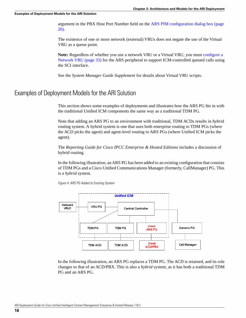
This section shows some examples of deployments and illustrates how the ARS PG fits in withthe traditional Unified ICM components the same way as a traditional TDM PG.
Note that adding an ARS PG to an environment with traditional, TDM ACDs results in hybridrouting system. A hybrid system is one that uses both enterprise routing to TDM PGs (wherethe ACD picks the agent) and agent-level routing to ARS PGs (where Unified ICM picks theagent).
The Reporting Guide for Cisco IPCC Enterprise & Hosted Editions includes a discussion ofhybrid routing.
In the following illustration, an ARS PG has been added to an existing configuration that consistsof TDM PGs and a Cisco Unified Communications Manager (formerly, CallManager) PG. Thisis a hybrid system.
Figure 4: ARS PG Added to Existing System
In the following illustration, an ARS PG replaces a TDM PG. The ACD is retained, and its rolechanges to that of an ACD/PBX. This is also a hybrid system, as it has both a traditional TDMPG and an ARS PG.
ARI Deployment Guide for Cisco Unified Intelligent Contact Management Enterprise & Hosted Release 7.5(1)
18
Chapter 2: Architecture and Models for the ARI Deployment
Examples of Deployment Models for the ARI Solution

Figure 5: ARS PG Replaces TDM PG
This next illustration shows a Unified ICM which includes only ARS PGs. This is not a hybridsystem. All routing is agent-level.
Figure 6: New Deployment with all ARS PGs
ARI Deployment Guide for Cisco Unified Intelligent Contact Management Enterprise & Hosted Release 7.5(1)
19
Chapter 2: Architecture and Models for the ARI Deployment
Examples of Deployment Models for the ARI Solution

ARI Deployment Guide for Cisco Unified Intelligent Contact Management Enterprise & Hosted Release 7.5(1)
20
Chapter 2: Architecture and Models for the ARI Deployment
Examples of Deployment Models for the ARI Solution
Installation and Configuration for the ARIDeploymentThis chapter explains how to perform installation for an ARI Deployment and what parametersto set for ARI in Configuration Manager. It concentrates on those tasks that are specific to, orare different for, ARI.
For complete instructions on installation and configuration, see the IPCC Installation andConfiguration Guide for Cisco IPCC Enterprise Edition and the ICM Installation Guide forCisco ICM Enterprise Edition.
Note that the values you enter during installation are 'machine' configurations and are reflectedin the Registry. Values that you enter in Configuration Manager are 'database' configurationsand must be in place before you can run the ARS PG.
This chapter contains the following topics:
• Installation, page 21• Configuration, page 31
Installation
The pages that follow explain the installation procedure and sequence.
About the Server Where You Install ARS PG
The ARS PG must be installed on a separate, dedicated server. Both CTI Server and CTI OSmust be co-located on that server. A VRU PG can also be installed on the ARS PG server.
Note: If your enterprise requires multiple ARS PGs, each must be on a unique server whereCTI Server and CTI OS are also installed.
ARI Deployment Guide for Cisco Unified Intelligent Contact Management Enterprise & Hosted Release 7.5(1)
21
Chapter 3

The following illustration represents an ARS PG Server on which the three components havebeen installed. Note that the OPC, PIM, and ARS Gateway are processes installed with the ARSPG.
Figure 7: Server for the ARS PG
Preparing a Server for the ARS PG
The first release in which the ARS PG is offered is Minor Release 7.2(1).
Release 7.2(1) is a Minor Release and cannot be installed directly. The dedicated server whereyou intend to install the ARS PG must first be installed with the base Release and then upgradedto Release 7.2(1).
(1) Bring the Server to the Base Release
For a server that is not at Release 7.0(0), use the Release 7.0(0) Media Setup to install thebase release with an ICM instance.
Note: An instance is a single installation of Unified ICM software and typically consists ofseveral components. On this ARS PG server, however, you will add only one component: CTIServer.
For a server that is already at Release 7.1(x), add the CTI Server component from Release7.1 Local Setup.
If you repurpose a Release 7.1(x) server to install the ARS PG, you might need to removecomponents that cannot co-reside with the ARS PG. See About the Server Where You Installthe ARS PG (page 21).
Why CTI Server is Added First
Adding the CTI Server component serves two purposes:
ARI Deployment Guide for Cisco Unified Intelligent Contact Management Enterprise & Hosted Release 7.5(1)
22
Chapter 3: Installation and Configuration for the ARI Deployment
Installation

1. Identifies the server as a PG node. This is necessary for the Release 7.2 installer you mustrun subsequently.
2. Fulfills the requirement that the CTI Server be located on the same server as the ARS PG.
For installation information, see the following:
• The chapter on CTI Server Setup in the ICM Installation Guide for Cisco ICM EnterpriseEdition Release 7.0(0).
• Installation Guide Cisco ICM/IPCC Enterprise & Hosted Editions Release 7.1(1).
Now: You now have a Release 7.0 or 7.1(x) server with only one component—CTI Server.
Next: Your next step is to upgrade this server to 7.2(1).
(2) Upgrade to 7.2(1)
Bring your CTI Server machine to Unified ICM Release 7.2(1).
The Router, Logger, and AW must also be upgraded to Release 7.2(1) before you add the ARSPG to the server. See the Installation Guide Cisco ICM/IPCC Enterprise & Hosted EditionsRelease 7.2(1).
Now: You now have a server at Minor Release 7.2(1).
Next: Your next step is to add the ARS PG in Configuration Manager. You do this at an AdminWorkstation. This initial configuration is necessary to obtain values for the Logical ControllerID and Physical Controller ID which you will enter on the PG installation screens.
(3) Add the ARS PG in Configuration Manager
Adding and saving the ARS PG in Configuration Manager gives you the Logical Controller IDand the Peripheral ID required on the installation screens. Perform this minimal configurationto acquire these two numbers. You will complete the ARS PG configuration after the installation.
Step 1 To access the Configuration Manager, at an Admin Workstation, select Start > Programs >ICM > Admin Workstation > Configuration Manager.
Step 2 In the ICM Configuration Manager, select Configure ICM > Peripherals > Peripheral > PGExplorer.
Step 3 Click Retrieve.
Step 4 Click Add.
The Logical Controller tab displays at the top right side of the panel.
ARI Deployment Guide for Cisco Unified Intelligent Contact Management Enterprise & Hosted Release 7.5(1)
23
Chapter 3: Installation and Configuration for the ARI Deployment
Installation
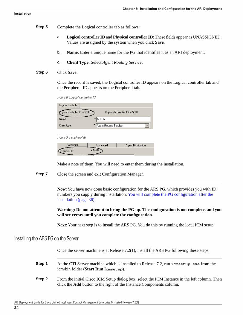
Step 5 Complete the Logical controller tab as follows:
a. Logical controller ID and Physical controller ID: These fields appear as UNASSIGNED.Values are assigned by the system when you click Save.
b. Name: Enter a unique name for the PG that identifies it as an ARI deployment.
c. Client Type: Select Agent Routing Service.
Step 6 Click Save.
Once the record is saved, the Logical controller ID appears on the Logical controller tab andthe Peripheral ID appears on the Peripheral tab.
Figure 8: Logical Controller ID
Figure 9: Peripheral ID
Make a note of them. You will need to enter them during the installation.
Step 7 Close the screen and exit Configuration Manager.
Now: You have now done basic configuration for the ARS PG, which provides you with IDnumbers you supply during installation. You will complete the PG configuration after theinstallation (page 36).
Warning: Do not attempt to bring the PG up. The configuration is not complete, and youwill see errors until you complete the configuration.
Next: Your next step is to install the ARS PG. You do this by running the local ICM setup.
Installing the ARS PG on the Server
Once the server machine is at Release 7.2(1), install the ARS PG following these steps.
Step 1 At the CTI Server machine which is installed to Release 7.2, run icmsetup.exe from theicm\bin folder (Start Run Icmsetup).
Step 2 From the initial Cisco ICM Setup dialog box, select the ICM Instance in the left column. Thenclick the Add button to the right of the Instance Components column.
ARI Deployment Guide for Cisco Unified Intelligent Contact Management Enterprise & Hosted Release 7.5(1)
24
Chapter 3: Installation and Configuration for the ARI Deployment
Installation

This opens the ICM Component Selection dialog box.
Step 3 At the ICM Component Selection dialog box, select Peripheral Gateway.
Figure 10: Setup: Select PG Component
This opens the Peripheral Gateway Properties screen.
Step 4 At the Peripheral Gateway Properties screen, locate Agent Routing Services in the Client TypeSelection column. Click Add >> to move it to the Selected Types column.
Figure 11: Setup: Select ARS Client Type
Note: No Client Type other than the Agent Routing Services Client Type can be added to thePG.
Step 5 Click Next to open the Peripheral Gateway Component Properties screen.
ARI Deployment Guide for Cisco Unified Intelligent Contact Management Enterprise & Hosted Release 7.5(1)
25
Chapter 3: Installation and Configuration for the ARI Deployment
Installation

Figure 12: Peripheral Gateway Component Properties
Step 6 Click Add to open the Add PIM popup and then click OK.
Figure 13: Setup: Add PIM popup
This opens the ARS PIM Configuration dialog box.
Step 7 Complete the ARS PIM Configuration dialog box as follows:
ARI Deployment Guide for Cisco Unified Intelligent Contact Management Enterprise & Hosted Release 7.5(1)
26
Chapter 3: Installation and Configuration for the ARI Deployment
Installation

Figure 14: Setup: ARS PIM Configuration dialog box
a. Check the Enable checkbox. The ARS PIM will not run if this box is unchecked.
b. The Peripheral Name defaults.
c. Peripheral ID: enter the ID for the peripheral. This ID value was created when you addedthe ARS PG in Configuration Manager. (page 24)
d. Gateway Provider defaults to Cisco.
e. Cisco Gateway Type defaults to Avaya.
f. PBX Host Name: Enter the Host name or IP address of the Server where the gateway willconnect via ASAI links. Valid numbers are from 1 to 8.
g. PBX Host Port Number: Enter the ASAI link number(s) used for event and routingcommunications. Examples of valid values for this field are /event 1 and /event 1,2/route 3
• The /event tag is used to indicate one or more ASAI links used for event notification and callcontrol. Use commas to delimit multiple link numbers (/event 1,3,5). Use a dash to indicatea range (/event 1-4)
• The /route tag is used to indicate the ASAI link used for SCI support via routing. Valid valuesinclude a single number from 1 to 8.
h. The Gateway Host Name defaults to the Local Host Name and is greyed out.
i. The Gateway Host Port Number defaults to 6101. You can change it if this port is usedby another application.
Step 8 Click OK.
ARI Deployment Guide for Cisco Unified Intelligent Contact Management Enterprise & Hosted Release 7.5(1)
27
Chapter 3: Installation and Configuration for the ARI Deployment
Installation
This closes the ARS PIM Configuration screen and returns you to the Peripheral GatewayComponent Properties screen.
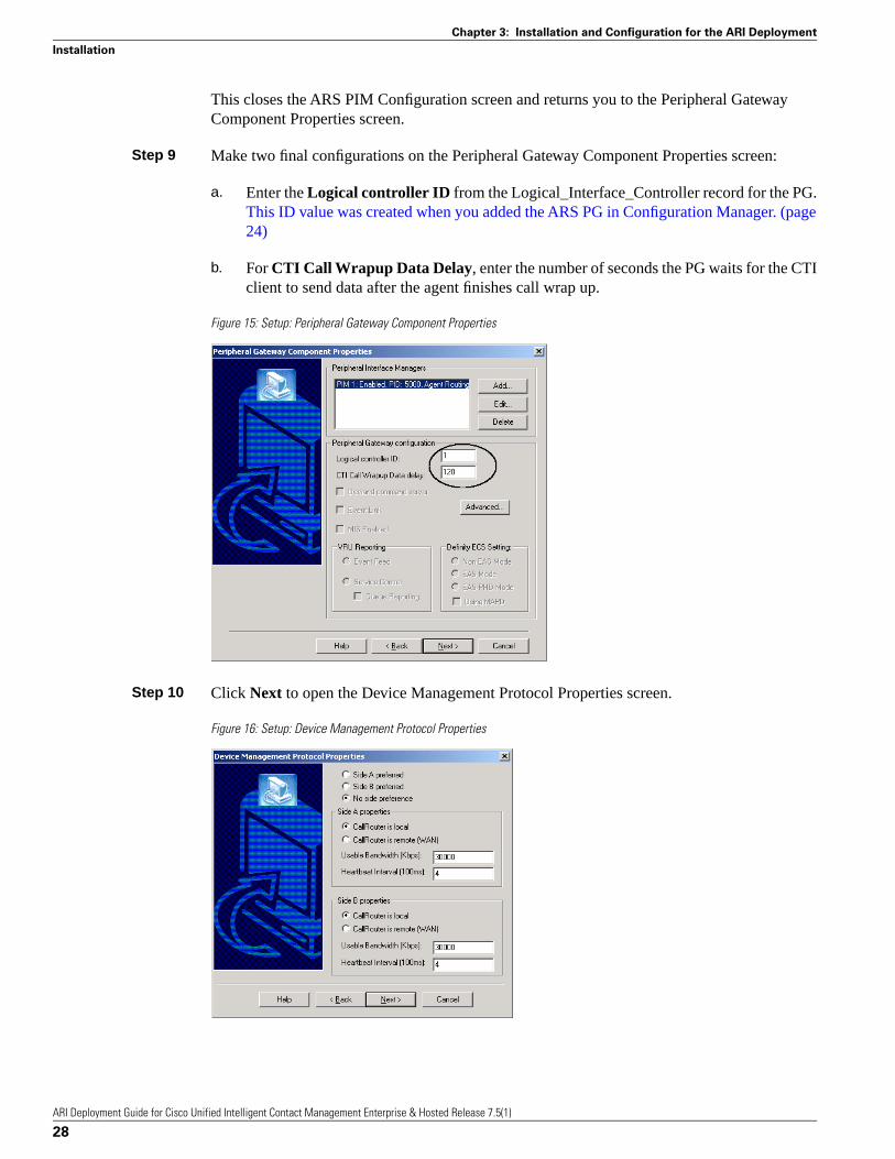
Step 9 Make two final configurations on the Peripheral Gateway Component Properties screen:
a. Enter the Logical controller ID from the Logical_Interface_Controller record for the PG.This ID value was created when you added the ARS PG in Configuration Manager. (page24)
b. For CTI Call Wrapup Data Delay, enter the number of seconds the PG waits for the CTIclient to send data after the agent finishes call wrap up.
Figure 15: Setup: Peripheral Gateway Component Properties
Step 10 Click Next to open the Device Management Protocol Properties screen.
Figure 16: Setup: Device Management Protocol Properties
ARI Deployment Guide for Cisco Unified Intelligent Contact Management Enterprise & Hosted Release 7.5(1)
28
Chapter 3: Installation and Configuration for the ARI Deployment
Installation

Accept the defaults, or change the configuration if necessary. Refer to the Help for fielddescriptions.
Step 11 Click Next to open the Peripheral Gateway Network Interfaces screen.
Figure 17: Setup: Peripheral Gateway Network Interfaces
Accept the defaults, or change the configuration if necessary. Refer to the Help for fielddescriptions.
Step 12 Click Next to open the Check Setup Information screen.
Figure 18: Setup: Check Setup Information
Step 13 Review your selections. Click Back to make revisions, or click Next to complete the PGconfiguration
Installing CTI OS Server on the ARS PG Server Machine
Install CTI OS Server co-resident with the ARS PG.
ARI Deployment Guide for Cisco Unified Intelligent Contact Management Enterprise & Hosted Release 7.5(1)
29
Chapter 3: Installation and Configuration for the ARI Deployment
Installation
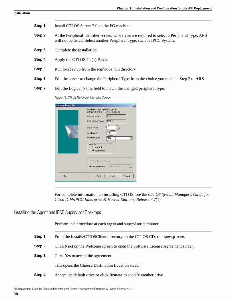
Step 1 Install CTI OS Server 7.0 on the PG machine.
Step 2 At the Peripheral Identifier screen, where you are required to select a Peripheral Type, ARSwill not be listed. Select another Peripheral Type, such as IPCC System.
Step 3 Complete the installation.
Step 4 Apply the CTI OS 7.2(1) Patch.
Step 5 Run local setup from the icm\ctios_bin directory.
Step 6 Edit the server to change the Peripheral Type from the choice you made in Step 2 to ARS.
Step 7 Edit the Logical Name field to match the changed peripheral type.
Figure 19: CTI OS Peripheral Identifier Screen
For complete information on installing CTI OS, see the CTI OS System Manager's Guide forCisco ICM/IPCC Enterprise & Hosted Editions, Release 7.2(1).
Installing the Agent and IPCC Supervisor Desktops
Perform this procedure at each agent and supervisor computer.
Step 1 From the Installs\CTIOSClient directory on the CTI OS CD, run Setup.exe.
Step 2 Click Next on the Welcome screen to open the Software License Agreement screen.
Step 3 Click Yes to accept the agreement.
This opens the Choose Destination Location screen.
Step 4 Accept the default drive or click Browse to specify another drive.
ARI Deployment Guide for Cisco Unified Intelligent Contact Management Enterprise & Hosted Release 7.5(1)
30
Chapter 3: Installation and Configuration for the ARI Deployment
Installation

Step 5 Click Next to open the Select Components screen.
Step 6 Select (check) the CTI Toolkit Desktop Client component that you want to install: Agent Desktopor IPCC Supervisor Desktop.
Step 7 Click Next to open the CTI OS Server Information screen.
Step 8 Enter the Name or IP Address and the Port Number for your CTI OS systems.
Step 9 Click Next open the Start Copying Files screen.
Step 10 Click Next to begin the installation.
When installation is complete, you are prompted to install the Security feature.
Step 11 Click OK to configure CTI OS security.
Step 12 At the Setup Complete screen, specify whether or not you want to restart your computer. Thenclick Finish to exit Setup.
For complete information on installing CTI OS, see the CTI OS System Manager's Guide forCisco ICM/IPCC Enterprise & Hosted Editions, Release 7.2(1).
Configuration
Special configuration is required in both ICM Configuration Manager and on the ACD/PBX tosupport ARI functionality.
This guide explains configuration that you define in Unified ICM Configuration Manager (page32).
In order for Unified ICM to route calls to the ACD/PBX, you must complete the followingconfiguration:
• Configure a Network VRU for the ARS PG. (page 33)
• Configure Agent Desk Settings for agents associated with the ARS PG. (page 34)
• Configure the ARS PG (page 36)
• Configure the ARS PG Peripheral. (page 37)
• Configure Agent Targeting Rules. (page 44) if you will use them.
• Configuring for Reporting (page 45)
• Other Configurations
– Agents (page 46)
ARI Deployment Guide for Cisco Unified Intelligent Contact Management Enterprise & Hosted Release 7.5(1)
31
Chapter 3: Installation and Configuration for the ARI Deployment
Configuration

– Skill Groups (page 47)
– Services (page 48)
– Network Trunk Groups and Trunk Groups (page 49)
– Dialed Numbers (page 49)
– Device Targets (page 49)
– Translation Routes (page 50)
About ACD/PBX Configuration
The configuration on the ACD/PBX varies per ACD/PBX. For the Avaya, it includesconfiguration of:
• One or more ASAI links
• Agent devices (stations)
• One and only one agent skill group that all agents log in to
• Feature access codes for the hard phones, if used
• VDN and vectors used for the Service Control Interface: call treatment, post-routing, queuing,and other processing of calls
It is important to keep your ICM configuration aligned with your ACD/PBX configuration.Changes and additions, such as those to agents and agent telephones, need to match.
See the appropriate System Manager Guide Supplement for details on ACD/PBX configuration.
About Configuration Manager
Configuration that you perform for Unified ICM is done from Configuration Manager.Configuration Manager is a utility on all Admin Workstations that you use to add, save, andedit configuration settings.
To access the Configuration Manager, at an Admin Workstation, select Start > Programs >ICM > Admin Workstation > Configuration Manager.
ARI Deployment Guide for Cisco Unified Intelligent Contact Management Enterprise & Hosted Release 7.5(1)
32
Chapter 3: Installation and Configuration for the ARI Deployment
Configuration

Figure 20: Configuration Manager
Configuring a Network VRU
You must configure a Network VRU before you can configure and save the ARS Peripheral.
For an ARI deployment, configure a Type 9 VRU whether you will use an external VRU orVirtual VRU scripts. If you do not configure a Type 9 network VRU, post-routed andtranslation-routed calls will fail.
When you configure the ARS PG Peripheral, you will specify the Type 9 Network VRU at theAdvanced tab (page 39).
Step 1 In the Configuration Manager, select Configure ICM > Targets > Network VRU > NetworkVRU Explorer. The Network VRU Explorer dialog box opens.
Step 2 Click Retrieve.
Step 3 Click Add.
Step 4 Complete the Network VRU tab:
a. For Name, enter a suitable name.
b. For Type, choose Type 9.
Note: The Network VRU must be “Type 9”. No other Network VRU Type is accepted.
c. Refer to the online help for other field explanations.
Step 5 Click Save and then click Close.
ARI Deployment Guide for Cisco Unified Intelligent Contact Management Enterprise & Hosted Release 7.5(1)
33
Chapter 3: Installation and Configuration for the ARI Deployment
Configuration
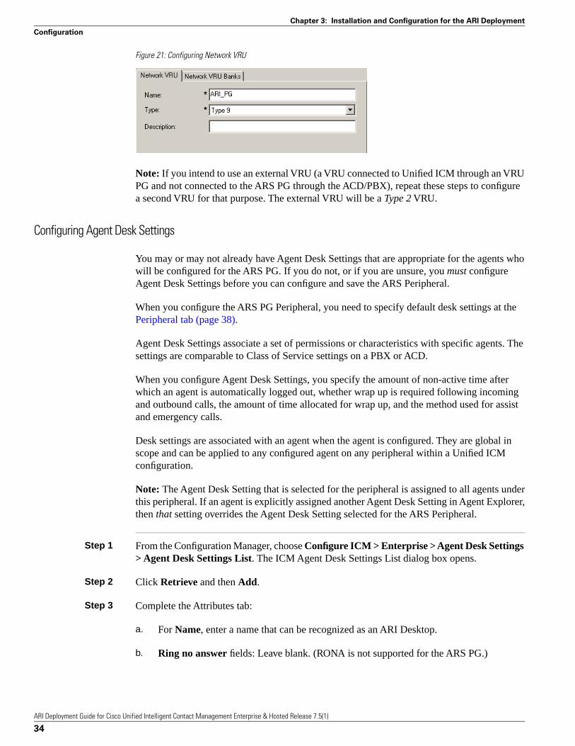
Figure 21: Configuring Network VRU
Note: If you intend to use an external VRU (a VRU connected to Unified ICM through an VRUPG and not connected to the ARS PG through the ACD/PBX), repeat these steps to configurea second VRU for that purpose. The external VRU will be a Type 2 VRU.
Configuring Agent Desk Settings
You may or may not already have Agent Desk Settings that are appropriate for the agents whowill be configured for the ARS PG. If you do not, or if you are unsure, you must configureAgent Desk Settings before you can configure and save the ARS Peripheral.
When you configure the ARS PG Peripheral, you need to specify default desk settings at thePeripheral tab (page 38).
Agent Desk Settings associate a set of permissions or characteristics with specific agents. Thesettings are comparable to Class of Service settings on a PBX or ACD.
When you configure Agent Desk Settings, you specify the amount of non-active time afterwhich an agent is automatically logged out, whether wrap up is required following incomingand outbound calls, the amount of time allocated for wrap up, and the method used for assistand emergency calls.
Desk settings are associated with an agent when the agent is configured. They are global inscope and can be applied to any configured agent on any peripheral within a Unified ICMconfiguration.
Note: The Agent Desk Setting that is selected for the peripheral is assigned to all agents underthis peripheral. If an agent is explicitly assigned another Agent Desk Setting in Agent Explorer,then that setting overrides the Agent Desk Setting selected for the ARS Peripheral.
Step 1 From the Configuration Manager, choose Configure ICM > Enterprise > Agent Desk Settings> Agent Desk Settings List. The ICM Agent Desk Settings List dialog box opens.
Step 2 Click Retrieve and then Add.
Step 3 Complete the Attributes tab:
a. For Name, enter a name that can be recognized as an ARI Desktop.
b. Ring no answer fields: Leave blank. (RONA is not supported for the ARS PG.)
ARI Deployment Guide for Cisco Unified Intelligent Contact Management Enterprise & Hosted Release 7.5(1)
34
Chapter 3: Installation and Configuration for the ARI Deployment
Configuration

c. Logout non-activity Time: Enter the number of seconds (between 10 and 7200) in whichthe agent can be in a not ready state before the Unified ICM automatically logs out theagent.
d. Work Mode on Incoming. Indicates whether wrap up is required or possible followingan incoming call. Select Required, Optional, Not Allowed, or Required from the drop-downlist.
e. Work Mode on Outgoing: Select one of the three options: Optional, Not Allowed, orRequired.
f. Wrap Up Time. Enter the number of seconds allowed for the agent to wrap up the call.
g. Assist Call Method. Select consultive call or blind conference from the drop-down listto indicate whether the ARS PG will create a consultive call or a blind conference call forthe supervisor assistance request.
h. Emergency Alert Method. Select consultive call or blind conference from the drop-downlist to indicate whether the ARS PG will create a consultive call or a blind conference callfor the emergency call request.
i. Description. Enter additional optional information about the agent desk settings.
j. Miscellaneous
Use the following boxes to select or de-select miscellaneous settings for an agent. Click on thebox to enable/disable the setting.
• Auto-answer. Indicates whether calls to the agent will be answered automatically. The agentis not required to take any action to answer the call.
• Idle reason required. Indicates whether an agent is required to enter a reason before enteringthe Idle state.
• Logout Reason Required. Indicate whether the agent is required to enter a reason beforelogging out.
• AutoRecord on Emergency. Not supported for ARI.
k. Outbound Access: Not supported for ARI.
Step 4 Click Save and then click Close.
Note that the Cisco Unified Mobile Agent field is not applicable for an ARI deployment. LeaveEnable Cisco Unified Mobile Agent unchecked.
ARI Deployment Guide for Cisco Unified Intelligent Contact Management Enterprise & Hosted Release 7.5(1)
35
Chapter 3: Installation and Configuration for the ARI Deployment
Configuration

Figure 22: Configuring Agent Desk Settings
Configuring the ARS PG
You added and saved the ARS PG before the installation to obtain the IDs required on theinstallation screens. In this step, you complete the configuration screens for the ARS PG andthe ARS Peripheral.
Step 1 In the ICM Configuration Manager, select Configure ICM > Peripherals > Peripheral > PGExplorer.
Step 2 Click Retrieve.
Step 3 Select the ARS PG you created before the installation. (page 23)
The Logical Controller tab displays at the top right side of the panel.
Step 4 Complete the Logical controller tab as follows:
a. Logical controller ID and Physical controller ID: These fields were assigned by thesystem when added the PG.
b. Name: Enter a unique name for the PG that identifies it as an ARI deployment.
c. Client Type: Select Agent Routing Service.
d. Configuration parameters: Leave blank.
e. Description and Physical controller description: Enter information to describe the PGand the physical controller.
ARI Deployment Guide for Cisco Unified Intelligent Contact Management Enterprise & Hosted Release 7.5(1)
36
Chapter 3: Installation and Configuration for the ARI Deployment
Configuration

f. Primary CTI address in either dotted numeric or name format. As the CTI server isinstalled at the PG, enter the PG address.
g. Secondary CTI address: The secondary CTI address is needed if a CTI server is installedat the PG and the ICM system is duplexed.
Figure 23: Configuring the PG
Configuring the ARS PG Peripheral: Peripheral Tab
Agents are grouped by assigning them to a peripheral, independent of their physical location.Unified ICM uses the peripheral assignment for call handling and administrative purposes.
You need to configure the ARS PG Peripheral so that you can associate agents, skill groups,and services with it.
Step 1 In the ICM Configuration Manager, select Configure ICM > Peripherals > Peripheral > PGExplorer.
Step 2 Click Retrieve.
Step 3 Highlight the ARS PG icon in the tree hierarchy in the left panel.
Step 4 Click Add Peripheral (lower left side of the dialog box).
Figure 24: Configuring the PG Peripheral
This displays a panel with seven tabs at the lower right of the dialog box, beneath the LogicalController tab.
ARI Deployment Guide for Cisco Unified Intelligent Contact Management Enterprise & Hosted Release 7.5(1)
37
Chapter 3: Installation and Configuration for the ARI Deployment
Configuration

At the Peripheral tab, enter values as follows:
Figure 25: Configuring the PG Peripheral: Peripheral Tab
Step 5 Name. An enterprise name for this peripheral. The name must be unique among all peripheralsin the enterprise.
Step 6 Peripheral name. The name of the peripheral as it is known at the site. Unlike the EnterpriseName field, the value of this field does not have to be unique.
Step 7 Client type. The type of the peripheral. The value for this field (Agent Routing Services) defaultsfrom the default from values you entered when you configured the PG. Do not change to anotherclient type - client type must be Agent Routing Services.
Step 8 Location. The peripheral's location. For example: the name of a city, building, or department.
Step 9 Abandoned call wait time. Minimum time in seconds an incoming call must be queued beforebeing considered an abandoned call if the caller hangs up.
Step 10 Configuration parameters. A string containing any parameters that must be sent to the deviceto initialize it. Refer to the instructions in the specific PBX supplement for instructions oncompleting this field.
Step 11 Call Control Variable Map. Leave blank.
Step 12 Description. Additional information about the peripheral.
Step 13 Default desk settings. select the Agent Desk Setting you have configured (page 34).
Step 14 Peripheral service level type. This is greyed out and cannot be selected.
Step 15 Service level type. This field is not available.
Step 16 Service level threshold. This field is not available.
Step 17 Enable post routing. This must be enabled (checked).
ARI Deployment Guide for Cisco Unified Intelligent Contact Management Enterprise & Hosted Release 7.5(1)
38
Chapter 3: Installation and Configuration for the ARI Deployment
Configuration

Complete the remaining tabs as explained in the following sections.
Caution: You can configure only one peripheral for each ARS PG. To configure a secondperipheral, you need to install a second ARS PG.
Configuring the ARS PG Peripheral: Advanced Tab
At the Advanced tab:
Figure 26: Configuring the PG Peripheral: Advanced Tab
Step 1 Available holdoff delay: Set this field to 0.
Step 2 Answered short calls threshold: Maximum duration, in seconds, for a short call. Any callswith a duration under the threshold are considered short. This field will track agents who hangup on callers.
Step 3 For Network VRU, select the Type 9 Network VRU you have configured (page 33).
Note: It is important to select the Type 9 Network VRU. You can save the ARS PG withoutselecting a Network VRU, but call routing fails without this Network VRU configuration, ifthe request is originated from the ARS Peripheral.
Step 4 Do not check Internal IPTA Only.
Step 5 For Agent targeting mode, options are as follows:
a. Device Target Preferred
The existing device target selection is used to determine the label. This is the default for systemsupgraded from an earlier release. Device targets are used to find labels, just as in earlier releases.Rules can be configured, as part of a strategy to switch over to them, but they are ignored.
If you make this selection, you must configure Device Targets (page 49).
b. Rule Preferred
This is the default option for newly-created periperals. If you retain this selection, you musthave configured Agent Targeting Rules (page 44).
ARI Deployment Guide for Cisco Unified Intelligent Contact Management Enterprise & Hosted Release 7.5(1)
39
Chapter 3: Installation and Configuration for the ARI Deployment
Configuration

The rules are used to create the label. The CallRouter uses the Agent Targeting Rule if oneexists. If no rule exists, the CallRouter then determines if a device target has been configured.If there is no Agent Targeting Rule and a device target has been configured, the CallRouter usesthe device target for routing the call. If no device target has been configured and no rule exists,the routing of the call fails.
c. Rules compare to existing Device Target
This option is available to assist customer testing of newly created rules for a peripheral thatpreviously used device targers.
Step 6 Refer to the online help to complete the other fields on this tab.
Configuring the ARS PG Peripheral: Agent Distribution and Skill Group Mask Tabs
At the Agent Distribution tab:
Figure 27: Configuring the PG Peripheral: Agent Distribution Tab
Step 1 Check Enable agent reporting.
Step 2 Check Agent event detail
Step 3 Distributor Site Name: Click New and enter the site name of the Admin Workstation to whichthe Unified ICM router and logger should send agent information. Note that the site name ofthe AW distributor is the same name that is entered during AW distributor set up. If nothing isentered for the site name during installation, this defaults to the host name.
Step 4 At the Skill Group Mask tab, no configuration is required for the ARI Deployment. Sub-skillgroups are not supported for ARI.
Configuring the ARS PG Peripheral: Routing Client Tab
At the Routing Client tab:
ARI Deployment Guide for Cisco Unified Intelligent Contact Management Enterprise & Hosted Release 7.5(1)
40
Chapter 3: Installation and Configuration for the ARI Deployment
Configuration

Figure 28: Configuring the PG Peripheral: Routing Client Tab
Step 1 Name: An enterprise name for this routing client. The name must be unique among all routingclients in the enterprise.
Step 2 Timeout Threshold: The maximum time, in milliseconds, the routing client can wait for aresponse to a routing request. The NIC sends a default response slightly before this threshold.
Step 3 Late Threshold: The threshold value, in milliseconds, for classifying responses as late. Anyresponse that exceeds this threshold is considered late even if it does not exceed theTimeoutThreshold.
Step 4 Timeout Limit: The maximum time, in seconds, for which the routing client waits for a response.If the routing client receives no responses within this limit, it terminates routing operation.
Step 5 For Default media routing domain, select None or Cisco_Voice.
Step 6 For Default call type, select the call type used for routing a call from this routing client in theevent the call cannot be categorized into any other Call Type defined in the system.
Step 7 Be sure Client Type is Agent Routing Service.
Step 8 Optionally, select (check) Network transfer preferred.
Configuring the ARS PG Peripheral: Default Route Tab
At the Default Route tab:
ARI Deployment Guide for Cisco Unified Intelligent Contact Management Enterprise & Hosted Release 7.5(1)
41
Chapter 3: Installation and Configuration for the ARI Deployment
Configuration

Figure 29: Configuring the PG Peripheral: Default Route Tab
Step 1 The Media routing domain, defaults to Cisco_Voice.
Step 2 For Route, no default route selected. Route selection is not mandatory.
Configuring the ARS PG Peripheral: Peripheral Monitor Tab
A peripheral monitor entity is defined as a physical resource that exists in the ACD/PBX to bemonitored by Unified ICM.
Peripheral Monitors are used to designate three classes of objects for the ARS Gateway.Depending on your requirements, you might need to configure some or all of these classes ofobjects, which are:
1. The skill group/hunt group defined on the Avaya ACD/PBX that agents can log into for hard phone support.
This extension is configured as a method to inform the ARS PG at startup that theACD/PBX skill group should be monitored to detect when agents log in or log off viatheir hard phones.
Each agent configured on the ACD/PBX must be assigned to one and only one ACD/PBXskill group/hunt group.
This skill is monitored by Unified ICM by the peripheral monitor configuration: type=station, extension = split extension, parameter = VDN_SKILL.
Enter only one VDN_SKILL in the Peripheral Monitor tab.
2. The Avaya VDNs that are used for routing. This includes the Virtual VRU script VDN.The extensions of these objects require an appropriately configured VDN on the ACD/PBX.
A VDN is an extension on the switch that does not terminate at an actual device. It is aninternal end-point that can take a call and perform programmable actions with the call.
3. The hard phone extensions, required when Agent Targeting Rules are used for routing.
ARI Deployment Guide for Cisco Unified Intelligent Contact Management Enterprise & Hosted Release 7.5(1)
42
Chapter 3: Installation and Configuration for the ARI Deployment
Configuration

Extensions are monitored at startup and are reported to the PIM by the ARS Gateway todetect when agents log in or log off via their hard phones. Having the extension in thePeripheral Monitor tab enables the synchronization of the hard phones and the softphones.
For Agent Targeting Rules functionality, entering the range of extensions on this tab takesthe place of configuring individual Device Targets for hard-phone monitoring.
Note: DO NOT configure extensions in both the Peripheral Monitor tab and asDeviceTargets. Extensions configured in the Peripheral Monitor tab can be used only foragent targeting rule routing. They will not work for regular Unified ICM routing to agents.
To configure the extensions:
– Specify a contiguous range by providing a high and low values separated by a space.
Non-contiguous ranges must be specified by entering distinct peripheral monitor tabvalues.
– The configuration string is /RANGE <lowExtension> <highExtension> /MONITOR y/HARDPHONE 2
Hardphone Level 2 is required to ensure synchronization between the agent’ssoftphone and the agent’s teleset device.
To configure only one extension, enter the same parameter for the <lowExtension>and <highExtension>.
Note: In the above Peripheral Configuration string, the parameters "/MONITOR"can be replaced by "/MON or /M" and "/HARDPHONE" can be replaced by "/HARDor /H".
For Example: The Peripheral Configuration string can be configured as:
/RANGE <lowExtension> <highExtension> /MON y/HARD 2
or
/RANGE <lowExtension> <highExtension> /M y/H 2
Figure 30: Configuring the PG Peripheral: Peripheral Monitor Tab
ARI Deployment Guide for Cisco Unified Intelligent Contact Management Enterprise & Hosted Release 7.5(1)
43
Chapter 3: Installation and Configuration for the ARI Deployment
Configuration

Configuring Agent Targeting Rules
Once the ARS Peripheral is saved, you can configure Agent Targeting Rules. You need to dothis if you specified you specify agent targeting mode at the Advanced tab (page 39) duringthe ARS PG configuration.
Note: You can configure Agent Targeting Rules only after the ARS PG is saved.
When you configure the ARS PG, you specify agent targeting mode at the Advanced tab (page39).
Options are Device Targets Preferred, Rules Preferred, and Rules compare to existing DeviceTarget.
If you selected Rules Preferred (which is the default for newly-created peripherals), then youmight need to configure Agent Targeting Rules if you have not already done so.
Agent Targeting Rules allow you to configure ICM call routing by specifying the agent extensionrange, instead of configuring device targets and labels for every phone and for every routingclient.
Although it is also possible to target agents using device targets, you might prefer to use agenttargeting rules, as this method simplifies the call routing configuration.
Step 1 In the Configuration Manager, select Configure ICM > Targets > Device Target > AgentTargeting Rule.
Step 2 Click Retrieve. Then click Add to display the Attributes tab.
This tab has three sections.
Step 3 For Name, enter a name for the rule.
Step 4 For Peripheral, select the peripheral with which the rule is associated.
Step 5 For Rule type, select one of the three options:
• Agent Extension Rule - for routing calls to a peripheral from a routing client which doesnot need any prefix.
Substitute Agent Extension Rule - for routing calls from a routing client that requires aprefix. Requires creating DID numbers for each agent logged in.
Translation Route Rule - for routing calls from a routing client to a peripheral that involvesa Translation Route. The Router creates a label consisting of a DID number that is shared toall calls and that ICM translates to an agent extension using the translation route feature. Thisfixed set of DIDs, shared among agents, reduces cost. Requires the configuration of atranslation route (page 50) between the origin and the destination.
ARI Deployment Guide for Cisco Unified Intelligent Contact Management Enterprise & Hosted Release 7.5(1)
44
Chapter 3: Installation and Configuration for the ARI Deployment
Configuration
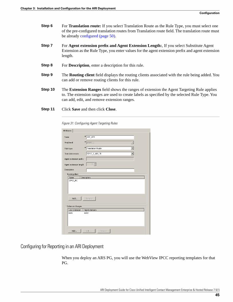
Step 6 For Translation route: If you select Translation Route as the Rule Type, you must select oneof the pre-configured translation routes from Translation route field. The translation route mustbe already configured (page 50).
Step 7 For Agent extension prefix and Agent Extension Length:, If you select Substitute AgentExtension as the Rule Type, you enter values for the agent extension prefix and agent extensionlength.
Step 8 For Description, enter a description for this rule.
Step 9 The Routing client field displays the routing clients associated with the rule being added. Youcan add or remove routing clients for this rule.
Step 10 The Extension Ranges field shows the ranges of extension the Agent Targeting Rule appliesto. The extension ranges are used to create labels as specified by the selected Rule Type. Youcan add, edit, and remove extension ranges.
Step 11 Click Save and then click Close.
Figure 31: Configuring Agent Targeting Rules
Configuring for Reporting in an ARI Deployment
When you deploy an ARS PG, you will use the WebView IPCC reporting templates for thatPG.
ARI Deployment Guide for Cisco Unified Intelligent Contact Management Enterprise & Hosted Release 7.5(1)
45
Chapter 3: Installation and Configuration for the ARI Deployment
Configuration

If you are familiar with configuring reporting for a Unified ICM environment, know that, forthe most part, configuration for ICM reports and IPCC reports is identical.
The Reporting Guide for Cisco IPCC Enterprise & Hosted Editions has detailed informationon Unified Contact Center (IPCC) reporting.
There is one configuration that affects certain IPCC Call Type reports and which is not used inICM. This configuration is for bucket intervals. Bucket intervals are associated with Call Typesand allow you to track data for calls abandoned or answered within specific time increments.
You can find the procedure to configure bucket intervals in the IPCC Installation andConfiguration Guide for Cisco IPCC Enterprise Edition
Notes on Other Configuration
Other configuration you might need to perform or modify when you set up the ARS PG includes:
• Agents (page 46)
• Skill Groups (page 47)
• Network Trunk Groups and Trunk Groups (page 49)
• Dialed Numbers (page 49)
• Device Targets (page 49)
• Translation Routes (page 50)
These configurations are explained in the IPCC Installation and Configuration Guide for CiscoIPCC Enterprise Edition and the Reporting Guide for Cisco IPCC Enterprise & Hosted Editions.
The information that follows notes any configuration parameters to be aware of for ARI.
As you perform standard configuration, be sure to select the ARS Peripheral or Routing Clientwhen you retrieve and add items to configure:
Figure 32: Select the ARS PG when Configuring
ARI Deployment Guide for Cisco Unified Intelligent Contact Management Enterprise & Hosted Release 7.5(1)
46
Chapter 3: Installation and Configuration for the ARI Deployment
Configuration

Agents
In a traditional Unified ICM configuration, agents associated with an ACD are dynamicallyconfigured by the TDM PG.
For an ARI Deployment, agents must be statically configured in the ICM database. The staticconfiguration defines the characteristics of an agent, as well as the address of the agent for calldelivery.
You also need to set up agents on the ACD/PBX for hard phone support and all agents configuredin the ACD/PBX configuration must be added to one and only one skill group.
To configure an agent, from Configuration Manager, click Configure ICM > Peripherals >Agent > Agent Explorer. Click Retrieve and then Add.
Complete the fields, referring to the online help.
Note:
• Auto-configuration of agents in not supported for an ARS peripheral. It is greyed out on theAdvanced tab (page 39).
• On the Advanced tab, enabling the agent state trace option can have a substantial performanceimpact on your system.
Skill Groups
In Unified ICM, a skill group is a collection of agents who share a common set of skills.
Skill groups are created in the Configuration Manager, and agents are assigned to them, also inthe Configuration Manager.
For an ARI Deployment, you must create at least one skill group for the ARS PG. Each agentconnected to the ACD/PCX must be a member an ICM skill group to be able to log in. This istrue whether or not the installation includes hard phone support.
You can configure additional skill groups as required.
If hard phone support is used, you also need to configure a skill group on the ACD/PBX forhard phone support and to add all agents on the ACD/PBX to this skill group. The skill groupextension configured on the ACD/PBX must match the skill group ID configured in UnifiedICM. This ACD/PBX skill group is entered on the Peripheral Monitor tab (page 43) duringARS PG Configuration.
To configure a Skill Group:
1. From Configuration Manager, select Configure ICM > Peripherals > Skill Group >Skill Group Explorer.
ARI Deployment Guide for Cisco Unified Intelligent Contact Management Enterprise & Hosted Release 7.5(1)
47
Chapter 3: Installation and Configuration for the ARI Deployment
Configuration

2. When the Skill Group Explorer window appears, click Add to create a new Skill Group,or click Retrieve and select an existing Skill Group.
For an ARI Deployment, be sure to check ICM picks the agent when configuring SkillGroups:
Figure 33: Selection when Configuring Skill Groups
“ICM picks the agent” (IPTA) means that the Central Controller is responsible for selectingthe actual agent who will handle a request, not just the Service or Skill Group.
In traditional Unified ICME deployments, the Central Controller determines whichAutomated Call Distributor (ACD) has the appropriate service or skill group to handle arequest and the ACD selects the actual agent to handle the call. The Central Controllerpre-routes calls by targeting an ACD, and the ACD post-routes calls by selecting the agent.
In an ARI environment, the ICM Central Controller handles the post-routing of requeststo agents. Choose the “ICM picks the agent” option for all skill groups that you configurefor the ARS PG.
3. Complete the configuration fields on all tabs.
4. After entering the Skill Group, you can assign agents to it as Skill Group Members.
Note: Sub-skill groups are not supported for the ARS PG.
Services
A service is a type of caller need, such as Billing or Technical Support. In a traditional TDMPG environment, Services and Service Members are configured to map to applications on theACD (such as VDN on the Avaya or Applications on the Aspect) so that the Unified ICM canreport on call treatment at the ACD.
Service and Service Members are not required for ARI deployments using the ARS PG.
In an ARI deployment, Call Types with the associated script provide call treatment. WebViewPeripheral Service reports are not supported. Use Call Type reports instead.
Refer to the Reporting Guide for Cisco IPCC Enterprise & Hosted Editions for information onplanning for VRU Application Reporting.
ARI Deployment Guide for Cisco Unified Intelligent Contact Management Enterprise & Hosted Release 7.5(1)
48
Chapter 3: Installation and Configuration for the ARI Deployment
Configuration
Network Trunk Groups and Trunk Groups
For an ARI Deployment, Network trunk groups and trunk groups are not required for agentrouting.
However, they need to be defined to support using Translation Routes to move the call to theARS PG, specifically:
• for translation routing to route points within the ACD/PBX used as an IVR, and
• where the Translation Route Rule Type is used for Agent Targeting Rules
Using the Translation Route to VRU node in the Script Editor requires you to define a networktrunk group and trunk group.
Configuring network trunk groups and trunk groups for the ARS PG is the same as for any otherPG.
In an ARI deployment, WebView Trunk and Trunk Group reports are not supported.
Dialed Numbers
The dialed number is the number that the caller dials to initiate the call and identifies the UnifiedICM routing script that should be run. Dialed numbers also need to be set up for ring on noanswer, dialed number plan entries, and for Supervisor/emergency calls.
Dialed numbers are used to represent entry points on the ACD/PBX related to new calls.
Ultimately, dialed numbers equate to a VDN on the Avaya ACD/PBX. Dialed numbers areconfigured for the VDN(s) on the Avaya ACD/PBX that will cause a New Call message to besent to the PIM. The Dialed Number associated with a new call will cause ICM to run a particularrouting script.
The Dialed Number configured in ICM must match the VDN configured on the Avaya ACD/PBXthat is responsible for handling new calls.
Device Targets
Configure Device Targets for an ARS PG as you do for IPCC.
For an ARI Deployment, if you use Agent Targeting Rules, there is no need to configure DeviceTargets.
If you do not use Agent Targeting Rules, you need to define Device Targets for the hard phonesso that Unified ICM can route calls to agent.
ARI Deployment Guide for Cisco Unified Intelligent Contact Management Enterprise & Hosted Release 7.5(1)
49
Chapter 3: Installation and Configuration for the ARI Deployment
Configuration

If you define Device Targets for an ARS PG, for the configuration parameter, enter /devTypeCiscoPhone /dn xxxx /monitor <peripheral id of ARS Peripheral> /
hardPhone 2
For example: /DEVTYPE CiscoPhone /DN 1000 /EXT 1000 /MONITOR 5000 /HARDPHONE 2
If you do not require hard phone synchronization, enter /DEVTYPE CiscoPhone /DN 1000/EXT 1000 /MONITOR 5000
Translation Routes
Configure Translation Routes if you have selected Rules Method and if you have selectedTranslation Route as the Rules Type.
Translation routes are also necessary for moving calls to and from the ACD/PBX and anotherPG.
How ECC variables are delivered to the ARS PG with the call.
In traditional Unified ICM, customers required a "Translation Route" to deliver all the CallContext Data (ECC variables included) to the TDM PG.
With the introduction of an ARS PG, there is no need to do this. The Call Context is alwaysavailable at the ARS PG when the call is delivered to the Agent.
However, if a call is queued at an external VRU that is connected to Unified ICM through aVRU PG, a Translation Route is needed to move the call from ARS PG to the VRU PG. Thisassures that the call context variables are available on the Agent Desktop when the call isdelivered to the Agent.
Configure Translation Routes for an ARS PG as you do for IPCC.
ARI Deployment Guide for Cisco Unified Intelligent Contact Management Enterprise & Hosted Release 7.5(1)
50
Chapter 3: Installation and Configuration for the ARI Deployment
Configuration
Queuing, Routing, and Reporting with an ARIDeployment
Queuing
Queued calls are calls that are being held at Queue Points at a Voice Response Unit (VRU)until an agent is available.
Queue Points allow the Unified ICM Router to direct calls to a VRU for call treatment prior toselecting a resource, or while waiting for a resource to become available.
The absence of an ACD makes Queue Points a necessity in an ARI configuration—there is noACD to queue the calls. Queue Point functionality replaces the queuing and call treatmentcapability provided by an ACD.
All queues are Enterprise Queues to a Queue Point VRU, controlled by Unified ICM using theService Control Interface (SCI).
The Service Control Interface (SCI):
• allows the Unified ICM Router to send call treatment instructions to the VRU under thecontrol of an ICM Routing Script
(For example, the ICM Script instructs the VRU to play announcements, play music, collectdigits, and eventually redirect the call to a location selected by the Router.
• allows the VRU to make use of the ICM’s call routing function to select the target for a callbeing transferred.
• allows the PG to collect data from a VRU for use in call routing, real time monitoring, andhistorical reporting.
ARI Deployment Guide for Cisco Unified Intelligent Contact Management Enterprise & Hosted Release 7.5(1)
51
Chapter 4

The Queue Point VRU (that is, a VRU serving as a Queue Point) may reside within the telephonenetwork. If supported by the ACD/PBX, the Queue Point can also be local to the PBX/ACDas a Virtual VRU (page 17)
• Network Queuing:the call is queued at a VRU that is connected to Unified ICM through aPG other than the ARS PG; for example, it is queued at a VRU that is connected to UnifiedICM by a VRU PG.
A call queued at a network queue point has an established SCI dialog with ICM. ICMeventually redirects the call to an available agent. ICM has control of the call while in thenetwork queue.
• Local Queuing: the call is queued at Virtual VRU that resides within the ACD/PBX.
Although traditional TDM ACD queuing methods do not allow the call to be externallycontrolled, the ARS PG employs a methodology that 'parks' the call on the Virtual VRU atthe ACD/PBX and uses post routing with extended wait times.
This 'Media Parking' queuing functionality is incorporated into the ARS PG and is alsocontrolled by the Cisco Service Control Interface (SCI) model.
Even when you intend to use only network queuing, you need to configure a Network VRUfor the ARI peripheral (page 33).
In an ARI deployment, therefore, ICM retains control of the call with both Network and Localqueuing. This ICM control is made possible by the Service Control Interface (SCI) protocol.
See Also
The Voice Response Unit (VRU) on page 15
Routing
The Unified ICM Router is notified by the network (pre-route case) or the ARS PG (post-routecase) that an incoming call has arrived.
Just as for a TDM PG, the ARS PG reports to the Unified ICM Router the current state of theagents assigned to the ACD/PBX peripheral. Based on this data, the Router invokes the routingscript (page 55) based on the Dialed Number, Caller Entered Digits and Calling Line ID.
These three parameters classify a call into a particular "Call Type" which in turn enables theRouter to run a scheduled ICM script corresponding to the Call type. The Agent is picked bythe Unified ICM Router based on the availability of the agent, the data for which is sent fromthe ARS PG to the Router.
Scripts are user-defined and must be configured prior to routing.
In the event an agent resource is not available, or if the customer must be prompted to determinewhere to send the call, the Script sends the call to a Queue Point.
ARI Deployment Guide for Cisco Unified Intelligent Contact Management Enterprise & Hosted Release 7.5(1)
52
Chapter 4: Queuing, Routing, and Reporting with an ARI Deployment
Routing

Pre-routing, post-routing, and translation routing are supported for the ARI deployment in thesame manner as they are supported in a traditional deployment.
For traditional ACDs, Unified ICM routes are a collection of peripheral targets.
In an ARI environment, calls can be routed to device targets and to peripheral targets. Devicetargets indicate individual agents to whom calls can be routed. Peripheral targets are used forTranslation Routing and for post-route points.
In an ARI environment, calls can be routed:
• directly to an agent phone, using Device Targets or Agent Targeting Rules
• to a Queue Point on a Virtual VRU and then to an agent
• to a network VRU and then to an agent
Device Targets and Agent Targeting Rules
For Unified ICM to send calls to agents on the ACD/PBX, you must configure routes to routedirectly to the agent phones.
There are two ways to do this. One is to use Device Targets and the other is to use AgentTargeting Rules.
The method you use depends on the Agent Targeting Mode indicated in the Advanced tab ofthe PG Configuration (page 39):
• If you selected Device Targets Preferred for the Agent Targeting Mode, you must configureDevice Targets.
• If you selected Rules Preferred for the Agent Targeting Mode, you must configure AgentTargeting Rules.
Device Targets
Device targets are configured to identify devices that can be targeted by the ICM Router todeliver a call to agent at the ACD/PBX. An agent is dynamically associated to the device targetat the time the he or she logs in.
A Device Target is a separately addressable device. It is not exclusively owned by a particularagent or associated with a particular peripheral. Device Targets are dynamically associated withagents for the duration of a given log-on session.
You must configure a Device Target for each independently addressable telephony device. Thiscan be a long process requiring hundreds of unique configurations.
See also the section on configuring Device Targets (page 49).
Agent Targeting Rules
ARI Deployment Guide for Cisco Unified Intelligent Contact Management Enterprise & Hosted Release 7.5(1)
53
Chapter 4: Queuing, Routing, and Reporting with an ARI Deployment
Routing

To target agents directly without configuring DeviceTargets, you need to create TranslationRoutes and Agent Targeting Rules.
Agent Targeting Rules eliminate the need to create hundreds of device targets.
When Agent Targeting Rules are used, agent extensions are in the Peripheral Monitor tab inthe ARS Peripheral.
Caution: In this case, do not configure Device Targets for these extensions. Extenstionsmust be configured either as Device Targets or as an entry on the Peripheral Monitorscreen, but not in both places.
See also the sections on the Peripheral Monitor tab (page 42) and on Configuring Agent TargetingRules (page 44)
Pre-Routing
Pre-routing enables call routing decisions to be made prior to a call being terminated at a callcenter.
In an ARI deployment, calls are routed directly to an agent or routed to a queue point if an agentis not available.
Pre-routing calls directly to agents requires that routes have been configured to agent phones,See Device Targets and Agent Targeting Rules (page 53).
Post Routing
The Post Routing feature allows the ACD/PBX to request a route to a new destination from theRouter.
The Router then makes a routing decision based on real-time enterprise wide resource availability.This allows previously terminated calls to be redirected to a new optimal location.
The new location could be on the same ACD/PBX, or the call could be sent to an alternatelocation.
Translation Routing
Translation routing ensures that the association between a call and its related data is maintainedthroughout the life of the call.
With traditional ACDs, translation routes allow the Unified ICM to pass data along with a calleven when the call is delivered to a generic resource at an ACD, such as a queue or an application.
In an ARI deployment, translation routing is used to route calls that are
• sent to an application on the ARS PG or queued at the ARS PG using the Virtual VRUfunctionality from another PG or Routing Client
ARI Deployment Guide for Cisco Unified Intelligent Contact Management Enterprise & Hosted Release 7.5(1)
54
Chapter 4: Queuing, Routing, and Reporting with an ARI Deployment
Routing

• sent from the ARS PG to another ICM PG.
• routed by Agent Targeting Rules where the Rule Type is Translation Route
Translation routes are not required when a call is transferred between agents within the sameACD/PBX.
See the Cisco White Paper on Working with Translation Routes (http://www.cisco.com/en/US/partner/products/sw/custcosw/ps1001/prod_technical_reference09186a0080134922.html).
Scripting
Unified ICM software uses routing scripts to determine the best destination for a call by assessingthe current information extracted by the PGs regarding call center activity.
When notified by the network (pre-route case) or the ARS PG (post-route case) that an incomingcall has arrived, the Router invokes the appropriate routing script to select a destination agent,based on the real-time data provided by the ARS PG.
Once an agent has been selected, the ICM Router instructs the network to deliver the call to theselected agent and notifies the target ARS PG that a call is on the way.
The ARS PG instructs the CTI Server to notify the agent desktop of the incoming call, whichallows an appropriate screen pop.
The PIM process running on the target ARS PG detects the arrival of the routed call. This eventis communicated by the PIM to the OPC process, which provides feedback to the Router viaan agent state update, as well as notification to the CTI Server.
Routing scripts are a representation of your business rules.
• You can create a specific set of scripts to be executed for each Call Type, such as Sales orSupport. For more granular reports, you might want to create multiple scripts; for example,you might create a script for initial call classification and also create scripts that route callsthat are sent to particular services or skill groups on different ACDs.
• You can schedule different scripts to be used at different times of day or different days ofthe week and year for each Call Type.
• Use ICM dialed numbers to direct calls to scripts that handle transfers.
• The Unified ICM Router scripting language provides a scriptwriter with much more powerthan is typically afforded a scriptwriter on an ACD. The customer can change the agentselection algorithm simply by modifying the Unified ICM Script associated with the givenCall Type.
• Translation routing scripts are used to route calls to the ARS PG by another PG.
ARI Deployment Guide for Cisco Unified Intelligent Contact Management Enterprise & Hosted Release 7.5(1)
55
Chapter 4: Queuing, Routing, and Reporting with an ARI Deployment
Scripting

In an ARI deployment, scripting on the PBX/ACD is limited to scripts for the Virtual VRU.See the System Manager Guide Supplement for Avaya ARS PG.
See the ICM Scripting and Media Routing Guide for Cisco ICM/IPCC Enterprise & HostedEditions for full details on scripting.
Using WebView with your ARI Deployment
The reporting statistics gathered for Unified ICM deployments with ARI are similar to thestatistics gather from Unified Contact Center (IPCC).
When you generate reports for the ARS PG and for the agents, skill groups, and other entitiesassociated with it, you need to select the IPCC report templates.
Figure 34: WebView Template Selection
IPCC reporting templates are supported for an ARI delployment, with the exception of thePeripheral Service and the Trunk and Network Trunk Group templates.
If you are familiar with a traditional ICM environment and with using the WebView ICM reporttemplates, you might benefit from familiarizing yourself with IPCC reporting.
See the Reporting Guide for Cisco IPCC Enterprise & Hosted Editions for details on IPCCReporting.
The Reporting Guide for Cisco IPCC Enterprise & Hosted Editions includes a discussion ofreporting in a hybrid deployment.
See also the section Configuring for Reporting in an ARI Deployment (page 45).
ARI Deployment Guide for Cisco Unified Intelligent Contact Management Enterprise & Hosted Release 7.5(1)
56
Chapter 4: Queuing, Routing, and Reporting with an ARI Deployment
Using WebView with your ARI Deployment
Desktops and Call Control
About Computer Telephony Integration
The ARS PG relays information to Unified ICM about the agent desktop—such as telephonyoperations and agent state—by way of a CTI link.
This CTI link is made available by the ICM CTI Object Server process, which is a server-basedsolution for deploying CTI applications. The CTI Server and CTI OS are installed on the ARSPG server, co-located with the ARS PG.
The CTI interface provides a CSTA message model that allows desktop clients and businessapplications to receive unsolicited call and agent state transition events. In addition to providingan unsolicited event feed, the CTI Server provides the ability to perform call control functions(such as transfers) from the agent and supervisor desktop.
In a direct desktop application environment, call event information is delivered to the targeteddesktop when the call is delivered. CTI Server reports call events and agent work state changesto the application as they occur through each stage of the call flow—from the moment a callarrives at the answering resource (the ACD/PBX) until the caller hangs up.
Agent Phones
Agents can log in and perform call control using the desktop softphones included with the CTI
OS3 and also by using "hard phones" (the standard agent handsets supported by the ACD/PBX).
3) CTI OS also provides CTI OS Active X Controls that allow you to design a user interface that will closely resemble the appearance of an ACD telephone set.
ARI Deployment Guide for Cisco Unified Intelligent Contact Management Enterprise & Hosted Release 7.5(1)
57
Chapter 5

Softphone
Although calls can be placed by either the hard phone or softphone, placing calls by the softphonehas the advantage of allowing Unified ICM routing scripts to be used to determine the bestdestination of the call based on the current condition of the Enterprise call center.
Softphones may be preferred or even required; for example, when reason codes are mandatedby the Agent Desktop settings.
The agent and supervisor desktops include a fully-functional softphones that enables telephonyfunctions from the desktop.
Buttons on the softphones for state and call control are similar on both agent and supervisordesktop softphones.
Note: For more information on Softphones Controls, Softphones, and Agent state, see the CTIOS Developer's Guide.
Hard Phones
The ARI deployment supports function keys on hard phones as backup in situations of serveror network failure.
For this release, supported "hardphones" are Avaya phones connected to the Avaya switch.
Using the hard phone, an agent can answer a call, place a caller on Hold, retrieve the call, transferand conference the call, and end the call.
Since all calls are routed by Unified ICM, the agent state changes supported on the hard phoneare the keys for Login, Logout, Auto In, and Aux In.
Note: The access codes must be programmed into the programmable buttons on the hard phones.DO NOT enter the codes manually. Manual entry is not supported.
When agents press the buttons for Log In, Log Out, Auto In, and Aux In, those states are reflectedin WebView reports and on the softphone.
Note: The exception to this is Log In. It is reflected in the reports but not on the softphone.
Call control is also synchronized between the hard phone and the softphone.
The Agent State changes recorded and synchronized from the hardphone functions are as follows:
• Unknown to Not Ready at Login
• Ready at Auto In
• Not Ready at Aux In
• Logged Out at Logout
ARI Deployment Guide for Cisco Unified Intelligent Contact Management Enterprise & Hosted Release 7.5(1)
58
Chapter 5: Desktops and Call Control
Agent Phones

An agent skill group/hunt group must be set up on the ACD/PBX so agents can log in usingtheir hard phone. Agents also need to be defined on the ACD/PBX to have the same agent IDas those used in the ICM configuration. These agents are then assigned to the ACD/PBX skillgroup.
If hard phone support is required, there might be ARS-specific requirements for agent ID andpassword at login. Refer to the appropriateSystem Manager Guide Supplement.
Synchronization
When the hard phone and softphone are synchronized, they look like a single device to UnifiedICM and the user.
Agents must log in using their softphone, even after logging in through their hard phone. Thisis required so that the softphone reflects the Agent States and Call control. There is no way toknow which Client (or SoftPhone) machine is being used by the Agent through a hardphone"log in". So the Softphone cannot show agent as logged in automatically.
Synchronization is performed for agent state activities and for call related actions. Agent stateactivities include logging in, changing state, and logging out. Call related actions includeanswering, transferring, conferencing, holding, and releasing calls.
Hard phone/softphone synchronization is performed through special configuration in bothUnified ICM and the ACD/PBX. ICM needs to know which hard phone devices need to besynchronized.
This is done with a configuration parameter in either the Peripheral Monitor tab or the DeviceTarget configuration.
• If you use Agent Targeting Rules (page 44), you must configure the Peripheral Monitor tab(page 42) for Hardphone Support Level 2 to ensure synchronization between the agent’ssoftphone and the agent’s teleset device.
• If you are not using Agent Targeting Rules, you must add each hard phone device in theDevice Target (page 49) configuration: /monitor [peripheral ID] /HARDPHONE 2.
Desktops and Call Control
Topics in this section include:
• The Agent Desktop (page 60)
• The Supervisor Desktop (page 60)
• Desktop Differences (page 61)
ARI Deployment Guide for Cisco Unified Intelligent Contact Management Enterprise & Hosted Release 7.5(1)
59
Chapter 5: Desktops and Call Control
Desktops and Call Control

The Agent Desktop
An Agent Desktop is a Windows-based desktop application that provides an interface to enablethe agent to perform agent state control and call control.
Agent Desktops are a required component of an ARI deployment.
The following agent desktop functionality is supported for the ARI Deployment:
• Login
• Logout
• Make calls
• Answer calls
• Transfer calls to another agent or to the Supervisor
• Place calls on Hold
• Conference calls to other agent(s)
• Conference the Supervisor into the call
• Request Supervisor assistance
• Reconnect back to the caller after receiving Supervisor assistance
• Release (hang up) a call.
The Supervisor Desktop
The Supervisor Desktop provides all of the functionality of the Softphone, with additionalfunctions for monitoring and managing Agent Team members.
In addition to the softphone, the supervisor desktop also has:
• A Team Real-Time Status window that provides supervisors with information about thecurrent state of agents who are part of their team.
• A CTI Statistics that displays individual statistics for the agent logged onto the phone, aswell as statistics for the supervisor who is currently logged on and for the skill groups towhich the supervisor and the supervisor's team belongs.
Note: Silent Monitoring is not supported.
ARI Deployment Guide for Cisco Unified Intelligent Contact Management Enterprise & Hosted Release 7.5(1)
60
Chapter 5: Desktops and Call Control
Desktops and Call Control

Supervisor features include the ability to respond to an agent request for assistance, the abilityto barge in to an existing ACD call, and the ability to remove the agent from the call once hehas barged in (intercept).
The following supervisor desktop functionality is supported for the ARI Deployment:
• Change the agent state of a supervised agent to Logout and Ready
• Perform call monitoring features (barge in and intercept)
• Support emergency and supervisor assist calls.
• Allow exchange of text messages between the supervisor and one of the agent team membersor all agent team members (chat).
• Control their own states for receiving assist calls.
Desktop Differences
In an ARI deployment, the Agent Desktop behavior is that of Unified Contact Center and notof Unified ICM.
Some differences you see when moving from a TDM PG to and ARS PG are the following:
• Agents cannot make calls from their softphones when they are in the Ready state. They mustbe in Not Ready state to initiate a call
• There is no dropdoen menu to select Work Mode (Unspecified, Auto In, or Manual). Theagent's work mode is controlled by the Agent Desk Settings configuration (page 34).
If you move from a traditional PG to the ARS PG, you might need to train contact center agentson the changed agent desktop behavior.
Agent States
The agent state model determines call delivery to agents and defines the valid state transitionsan agent may initiate. The agent state model for an ARI deployment is based on the modelcreated for Unified Contact Center. Existing TDM PBXs with traditional ACD software mayhave existing Agent State Models that differ from this model.
These are the agent state values that are relayed to the Unified ICM Router by the ARS PG.
DescriptionState
The agent has logged on to the ACD/PGX. This state does notnecessarily indicate that the agent is ready to accept calls.
Login
The agent has logged out of the ACD/PBX and cannot accept anyadditional calls.
Logout
ARI Deployment Guide for Cisco Unified Intelligent Contact Management Enterprise & Hosted Release 7.5(1)
61
Chapter 5: Desktops and Call Control
Agent States

DescriptionState
The agent is unavailable for any call work.NotReady
The agent is ready to accept a call.Available
The agent is currently talking on a call.Talking
The agent is performing wrapup work and will enter NotReady statewhen the wrapup is complete.
WorkNotReady
The agent is performing wrapup work and and will enter Ready statewhen the wrapup is complete.
WorkReady
The agent is busy performing a task (is Talking, WorkReady,Reserved, or Hold state in another SkillGroup.
BusyOther
The agent is reserved for a call that will arrive at the ACD/PBXshortly.
Reserved
The agent state is currently unknown.Unknown
The agent currently has all calls on hold.Hold
Changing Agent State from the Desktop
Desktop agent state controls include:
• Login/Logout
• Ready/NotReady
Depending on the Agent Desk Setting configuration (page 34), NotReady might require aReason Code.
• Wrap up
Depending on the Agent Desk Setting configuration (page 34), wrapup might be required,optional, or not allowed. The agent state that is comunicated to Unified ICM depends on theconfiguration.
Notes on Agent State Transitions
• Login
At log in, agents are put in a “Not Ready” state and cannot receive routed calls until theyclick the Ready button.
• Ready/Available: When the agent clicks the “Ready” button, the agent enters the Availablestate and can receive routed calls
• An agent in the Available state cannot make a call (the line buttons are dimmed). The agentmust click the “Not Ready” button and become unavailable before being allowed to make acall.
ARI Deployment Guide for Cisco Unified Intelligent Contact Management Enterprise & Hosted Release 7.5(1)
62
Chapter 5: Desktops and Call Control
Agent States
An agent in the Available state cannot log out (the logout button is dimmed). The agent mustclick the “Not Ready” button and become unavailable before being allowed to logout.
• Not Ready: Agents must be in a “Not Ready” state in order to make a call.
Transitions to the Not Ready state might be disallowed if the Router has sent a call to theagent within the last 10 seconds.
• WorkReady and WorkNotReady: The difference between Work Ready and Work NotReady is that Work Ready transitions to Ready, and Work Not Ready transitions to NotReady.
While on a call, if an agent clicks on the "Make Ready" button and then clicks Wrap up, thestate transitions are as Talking -> Work Ready -> Ready.
While on a call, if an agent clicks on the "Make Not Ready" button and then clicks Wrapup,the state transitions are as Talking -> Work Not Ready -> Not Ready
• Agent states for receiving a routed call: Talking
Notes:
1. If certain options (such as Idle Reason or Logout Reason) are checked on the Agent DeskSettings, dialog boxes display prompting for a reason. Transition cannot occur until theagent enters a reason. If the agent does not enter a reason and the Work Mode timer expires,the agent is transitioned to the Ready state and the dialog closes.
2. When the agent is talking and agent state buttons are enabled, once the agent presses theReady, Not Ready, or Wrap buttons, that button becomes disabled. If the agent then pressesa subsequent agent state button, the former button becomes enabled and the most recentlypressed button becomes disabled. The last button pressed before the call ends defines thenext agent state.
ARI Deployment Guide for Cisco Unified Intelligent Contact Management Enterprise & Hosted Release 7.5(1)
63
Chapter 5: Desktops and Call Control
Agent States

ARI Deployment Guide for Cisco Unified Intelligent Contact Management Enterprise & Hosted Release 7.5(1)
64
Chapter 5: Desktops and Call Control
Agent States

Index
ACD/PBX....5, 15
agent skill groups....47
configuring....32
currently supported for ARI....6
Active Directory....9
Administrative Workstation (AW)....14, 23, 32
Advanced tab (ARS PG)....39
Agent Desk Settings....34
agent desktop....60
changing states....62
Agent Distribution tab (ARS PG)....40
agent-level routing....18
Agent Routing Integration (see ARI)....5
Agent Routing Services
client type....25
agents
configuring....47
agent states
and Agent Desk Setting configuration....34
and hard phones....58
changing at desktop....62
transitions....62
Agent Targeting Mode....39
Agent Targeting Rules....7, 53
configuring....44
ARI
deployment models....18
overview....5
reporting....6
supported features....7
unsupported features....8
ARS Gateway....13, 21
ARS PG....5, 22
ARS Gateway....13
configuring....23, 36
currently supported....6
installing....24
in the Unified ICM enviroment....12
OPC....13
ARS PG server....21
preparing for the ARS PG....22
Central Controller....11
Central Database....11
Cisco product name changes....1
Configuration Manager....31, 32
configuring
ACD/PBX....32
Agent Desk Settings....34
agents....47
Agent Targeting Rules....44
ARS PG....23, 36
ARS PG Advanced tab....39
ARS PG Agent Distribution tab ....40
ARS PG Default Route tab....41
ARS PG Peripheral Monitor tab....42
ARS PG Peripheral tab....37
ARS PG Routing Client tab....40
ARS PIM....26
Device Targets....49
hard phone extensions....43
network VRU....33
reporting....45
skill groups....47
translation Routes....50
cradle-to-grave tracking....7
CTI OS....15, 21
installing....29
ARI Deployment Guide for Cisco Unified Intelligent Contact Management Enterprise & Hosted Release 7.5(1)
Index 65
Index

CTI Server....14, 21, 22, 57
installing....22
Default Route tab (ARS PG)....41
desktops....15
agent....60
behavior in ARI deployment....61
configuring Agent Desk Settings....34
installing....30
supervisor....60
Device Targets....39, 53
Device Targets
configuring....49
dialed numbers....49
ECC variables....50
enable agent reporting....40
enterprise routing....18
fault tolerance....10
feature access codes....58
hard phone
extensions....42, 47
synchronization....59
hard phones....57
access codes....58
agent states....58
supported....58
hybrid deployment....18
installing
ARS PG....24
CTI OS....29
CTI Server....22
desktops....30
Release 7.2(1)....23
internal port switching....15
ISAGI....13, 17
IVR....15
local setup....22
Logger....11
media setup....22
Microsoft Windows....9
multi-media integration....8
Network trunk groups....49
network VRU....15, 18, 39, 52
configuring....33
OPC....12
for ARS PG....13, 21
operating system....9
Outbound Option....8
Peripheral Gateway (see PG)....11
Peripheral Monitor tab (ARS PG)....42
Peripheral tab (ARS PG)....37
PG....11
phone synchronization....43
PIM....12
for ARS, configuring....26
for ARS PG....21
post-routing....54
pre-routing....54
queue points....51, 52
queuing....6, 51
Release 7.2(1)
ARS PG....22
reporting....6, 56
configuring....45
enable agent reporting....40
templates....45
unsupported reports....8
RONA....8, 34
Router....11
routing....6, 52
agent-level....18
ARI Deployment Guide for Cisco Unified Intelligent Contact Management Enterprise & Hosted Release 7.5(1)
Index 66
Index

enterprise....18
hybrid....18
pre-routing....54
scipts....55
Routing Client tab (ARS PG)....40
SCI....17, 51
scripts....55
server platforms....10
Service Control Interface (see SCI)....15
services....48
silent monitoring....8
skill groups
ACD/PBX....42, 47
configuring....47
softphone
synchronization....59
softphones....57
sub-skill groups....8, 40, 48
supervisor desktop....60
synchronization....43
system architecture
Adminstrative Workstation....14
Central Controller....10
Logger....11
TDM ACD
retaining existing hardware....6
telephone network....10, 15
translation routes....45
translation toutes
configuring....50
Type 9 VRU....33
Virtual VRU (VVRU)
scripts....15, 17, 42
VRU....15
WebView....45, 56
ARI Deployment Guide for Cisco Unified Intelligent Contact Management Enterprise & Hosted Release 7.5(1)
Index 67
Index