Area Scanner - livingston-products.com · The ML8740A Area Scanner is a scanner for performing...
12
ML8740A Area Scanner W-CDMA: 2110 to 2170 MHz GSM: 925 to 960 MHz, 1805 to 1880 MHz For Performing Area Tests and Maintenance of W-CDMA and GSM Base Stations
Transcript of Area Scanner - livingston-products.com · The ML8740A Area Scanner is a scanner for performing...
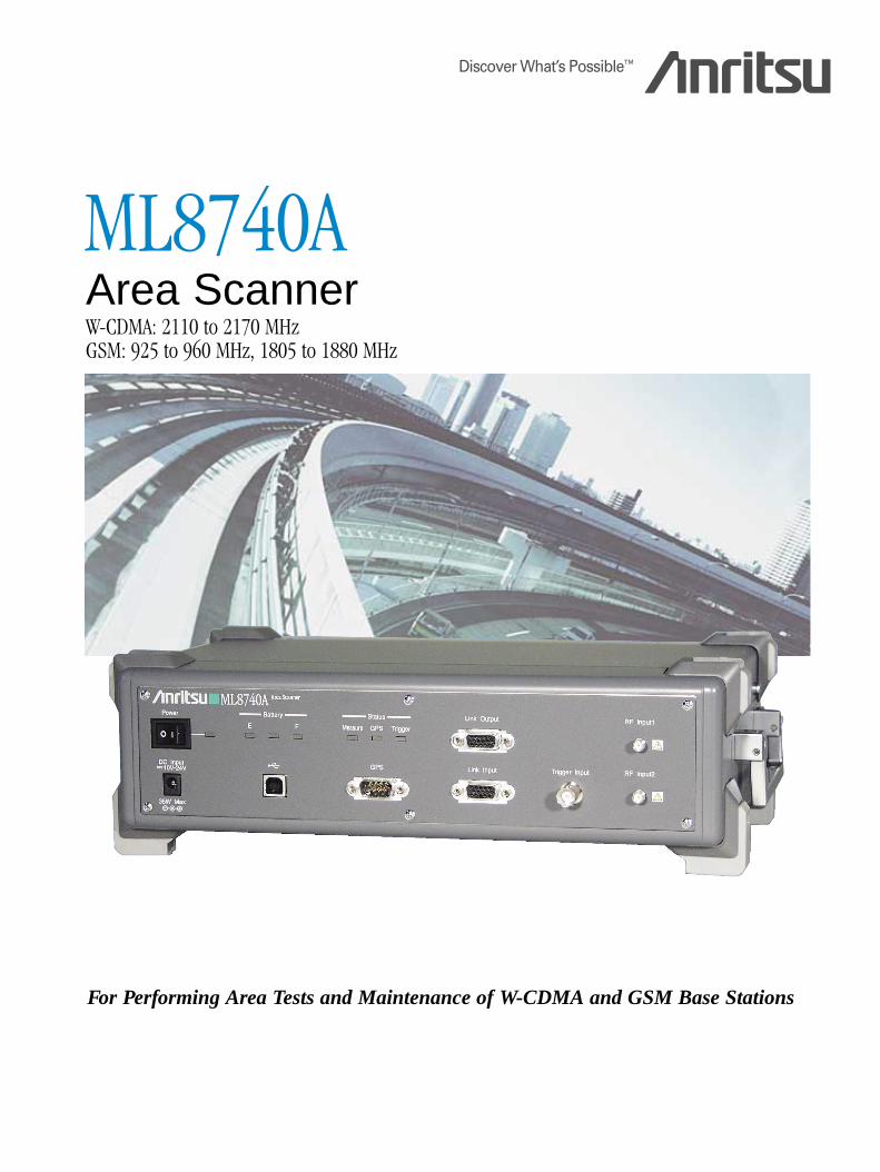
ML8740AArea ScannerW-CDMA: 2110 to 2170 MHzGSM: 925 to 960 MHz, 1805 to 1880 MHz
For Performing Area Tests and Maintenance of W-CDMA and GSM Base Stations
2
The ML8740A Area Scanner is a scanner for performing driving tests for optimizing base station service areas. Because of its excellent hardware performance, it can be used to for accurate area-coverage tests even in severe measurement environments with high interference because it can obtain radio wave carrier characteristics withhigh reliability.When used in combination with the Two Carrier Measurement Function and GSM Measurement Software options,either two W-CDMA base stations on different frequencies or a W-CDMA and GSM base station can be measuredsimultaneously. The data collection efficiency for drive testing is greatly improved compared to earlier products. Furthermore, installing the BCH Demodulation Software option permits confirmation of cell traffic data and basestation settings, offering support for discovering base stations with insufficient traffic capacity, and preventing configuration errors.
Simultaneous W-CDMA and GSM Measurement Installing the optional ML8740A-001 Two CarrierMeasurement Function and the MX874002A GSMMeasurement software enables simultaneous W-CDMA andGSM measurement. The data collection efficiency for drivetesting is greatly improved.
Simultaneous Measurement of Two CarrierFrequencies and Diversity function
By using the ML8740A-001 Two Carrier MeasurementFunction option, two carrier frequencies can be measuredsimultaneously.In addition, the W-CDMA transmission diversity formatRSCP of the CPICH can be measured by using the diversity function.
High-speed and High-accuracy Area AnalysisRSCP, Ec/No, and SIR can be measured at 30 cm intervals(using specified base station and single-channel measure-ments) while traveling at 100 km/h in a monitoring vehicleto provide fast and accurate area analysis.
High-speed Search with SCHWhen SCH search is selected in unspecified base stationmode, CPICH can be searched at high speed using thesame SCH search method as a UE. As one measurementexample, 10 channels are searched for 4 sec on averageand then the measurement is started.
Correlation with GPS Positioning DataWhen the GPS receiver is connected, measurement data isrecorded with GPS positioning data (latitude and longitude).
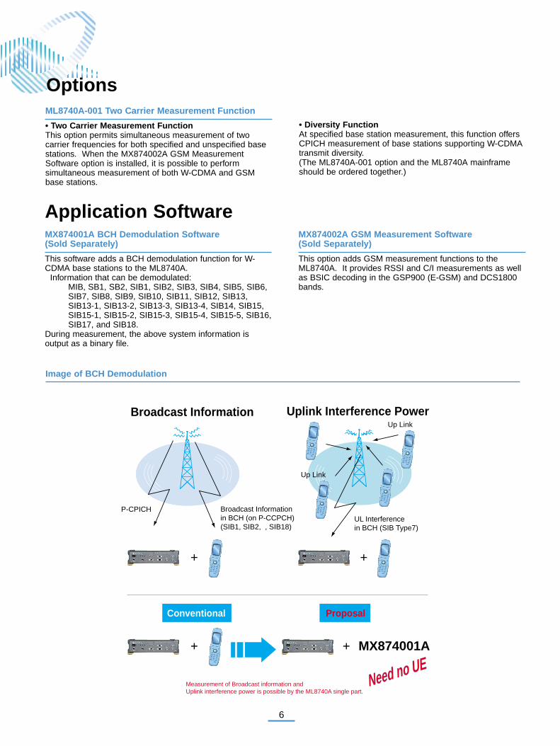
Checking broadcast information by BCH demodulation
For W-CDMA measurement, the W-CDMA base stationBCH data can be obtained via the MX874001A applicationsoftware without using the UE. Since the uplink interference power corresponding to the measured CPICHvalue is displayed in real time, cell traffic data can bechecked. And since all SIBs (System Information Blocks)are supported, it is possible to check whether the base station parameters are set as designed.
Specific distance measurement using car speedpulses
When a car speed pulse is used as an external trigger,measurements can be performed at specific distances.The measurement period can be designated by the pulsecount or distance when measuring using the external trigger.
5-hour Battery OperationIn the standard configuration, the lithium-ion battery packprovides 5 hours of operation and a spare battery packsolves even long-term measurement problems.
For Performing Area Tests and Maintenance of W-CDMA and GSM Base Stations
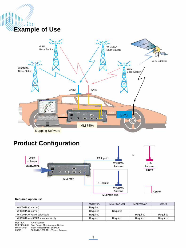
Example of Use
USBUSB
GPS
GSMBase Station
GSMBase Station
W-CDMABase Station
W-CDMABase Station
GPS Satellite
ANT2 ANT1
ML8740A
Mapping Software
Required option list
ML8740A Area ScannerML8740A-001 Two Carrier Measurement OptionMX874002A GSM Measurement SoftwareZ0779 900 MHz/1800 MHz Vehicle Antenna
ML8740A ML8740A-001 MX874002A Z0779W-CDMA (1 carrier) RequiredW-CDMA (2 carrier) Required RequiredW-CDMA or GSM selectable Required Required RequiredW-CDMA and GSM simultaneously Required Required Required Required
MX874002A
GSMsoftware
RF Input 1
RF Input 2
W-CDMAAntenna
W-CDMAAntenna
GSMAntenna
ML8740A
ML8740A-001
or
Option
Z0779
Product Configuration
3
4
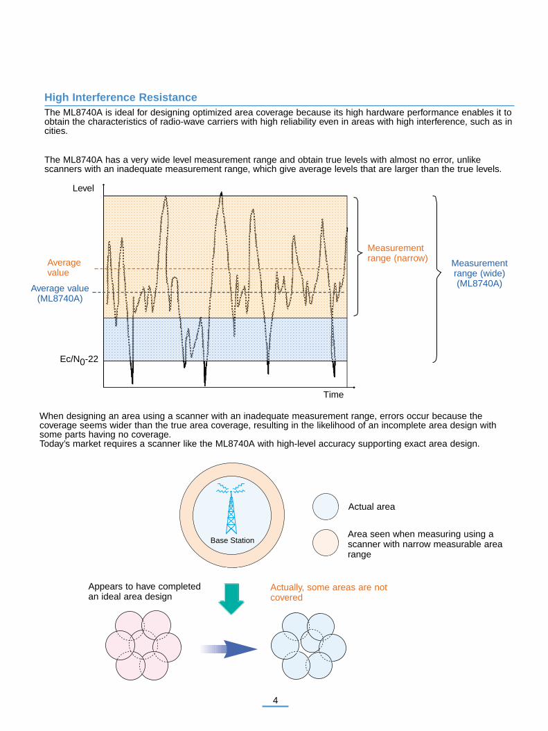
High Interference ResistanceThe ML8740A is ideal for designing optimized area coverage because its high hardware performance enables it toobtain the characteristics of radio-wave carriers with high reliability even in areas with high interference, such as incities.
The ML8740A has a very wide level measurement range and obtain true levels with almost no error, unlike scanners with an inadequate measurement range, which give average levels that are larger than the true levels.
When designing an area using a scanner with an inadequate measurement range, errors occur because the coverage seems wider than the true area coverage, resulting in the likelihood of an incomplete area design withsome parts having no coverage.Today’s market requires a scanner like the ML8740A with high-level accuracy supporting exact area design.
Average value
Average value(ML8740A)
Level
Ec/N0-22
Time
Measurementrange (narrow) Measurement
range (wide)(ML8740A)
Appears to have completedan ideal area design
Actually, some areas are notcovered
Actual area
Area seen when measuring using ascanner with narrow measurable arearange
Base Station
5
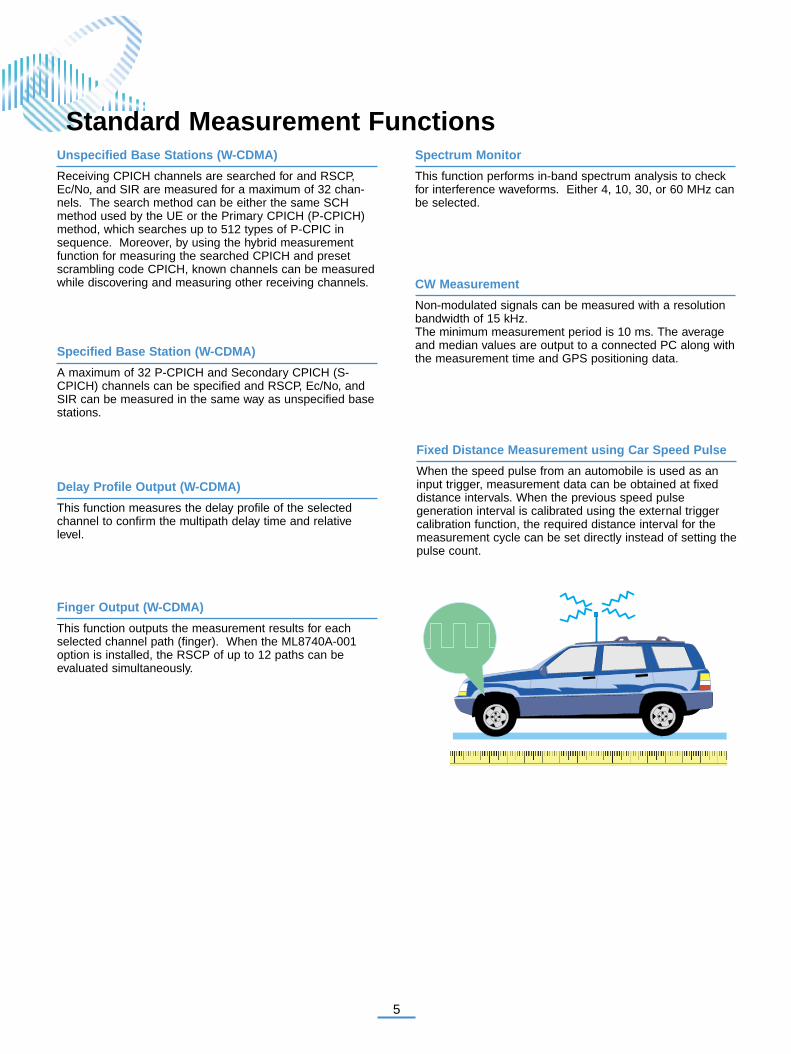
Fixed Distance Measurement using Car Speed Pulse
When the speed pulse from an automobile is used as aninput trigger, measurement data can be obtained at fixeddistance intervals. When the previous speed pulse generation interval is calibrated using the external triggercalibration function, the required distance interval for themeasurement cycle can be set directly instead of setting thepulse count.
Standard Measurement FunctionsUnspecified Base Stations (W-CDMA)
Receiving CPICH channels are searched for and RSCP,Ec/No, and SIR are measured for a maximum of 32 chan-nels. The search method can be either the same SCHmethod used by the UE or the Primary CPICH (P-CPICH)method, which searches up to 512 types of P-CPIC insequence. Moreover, by using the hybrid measurementfunction for measuring the searched CPICH and presetscrambling code CPICH, known channels can be measuredwhile discovering and measuring other receiving channels.
Specified Base Station (W-CDMA)
A maximum of 32 P-CPICH and Secondary CPICH (S-CPICH) channels can be specified and RSCP, Ec/No, andSIR can be measured in the same way as unspecified basestations.
Delay Profile Output (W-CDMA)
This function measures the delay profile of the selectedchannel to confirm the multipath delay time and relativelevel.
Finger Output (W-CDMA)
This function outputs the measurement results for eachselected channel path (finger). When the ML8740A-001option is installed, the RSCP of up to 12 paths can be evaluated simultaneously.
Spectrum Monitor
This function performs in-band spectrum analysis to checkfor interference waveforms. Either 4, 10, 30, or 60 MHz canbe selected.
CW Measurement
Non-modulated signals can be measured with a resolutionbandwidth of 15 kHz.The minimum measurement period is 10 ms. The averageand median values are output to a connected PC along withthe measurement time and GPS positioning data.
6
Up Link
Up Link
Uplink Interference PowerBroadcast Information
Broadcast Informationin BCH (on P-CCPCH)(SIB1, SIB2, , SIB18)
UL Interferencein BCH (SIB Type7)
P-CPICH
+
+ +
+
Conventional Proposal
MX874001A
Need no UENeed no UE
Measurement of Broadcast information and Uplink interference power is possible by the ML8740A single part.
Image of BCH Demodulation
ML8740A-001 Two Carrier Measurement Function
• Two Carrier Measurement FunctionThis option permits simultaneous measurement of two carrier frequencies for both specified and unspecified basestations. When the MX874002A GSM MeasurementSoftware option is installed, it is possible to perform simultaneous measurement of both W-CDMA and GSMbase stations.
• Diversity FunctionAt specified base station measurement, this function offersCPICH measurement of base stations supporting W-CDMAtransmit diversity.(The ML8740A-001 option and the ML8740A mainframeshould be ordered together.)
MX874002A GSM Measurement Software (Sold Separately)
This option adds GSM measurement functions to theML8740A. It provides RSSI and C/I measurements as wellas BSIC decoding in the GSP900 (E-GSM) and DCS1800bands.
MX874001A BCH Demodulation Software (Sold Separately)
This software adds a BCH demodulation function for W-CDMA base stations to the ML8740A.
Information that can be demodulated: MIB, SB1, SB2, SIB1, SIB2, SIB3, SIB4, SIB5, SIB6,SIB7, SIB8, SIB9, SIB10, SIB11, SIB12, SIB13,SIB13-1, SIB13-2, SIB13-3, SIB13-4, SIB14, SIB15,SIB15-1, SIB15-2, SIB15-3, SIB15-4, SIB15-5, SIB16,SIB17, and SIB18.
During measurement, the above system information is output as a binary file.
Application Software
Options
7
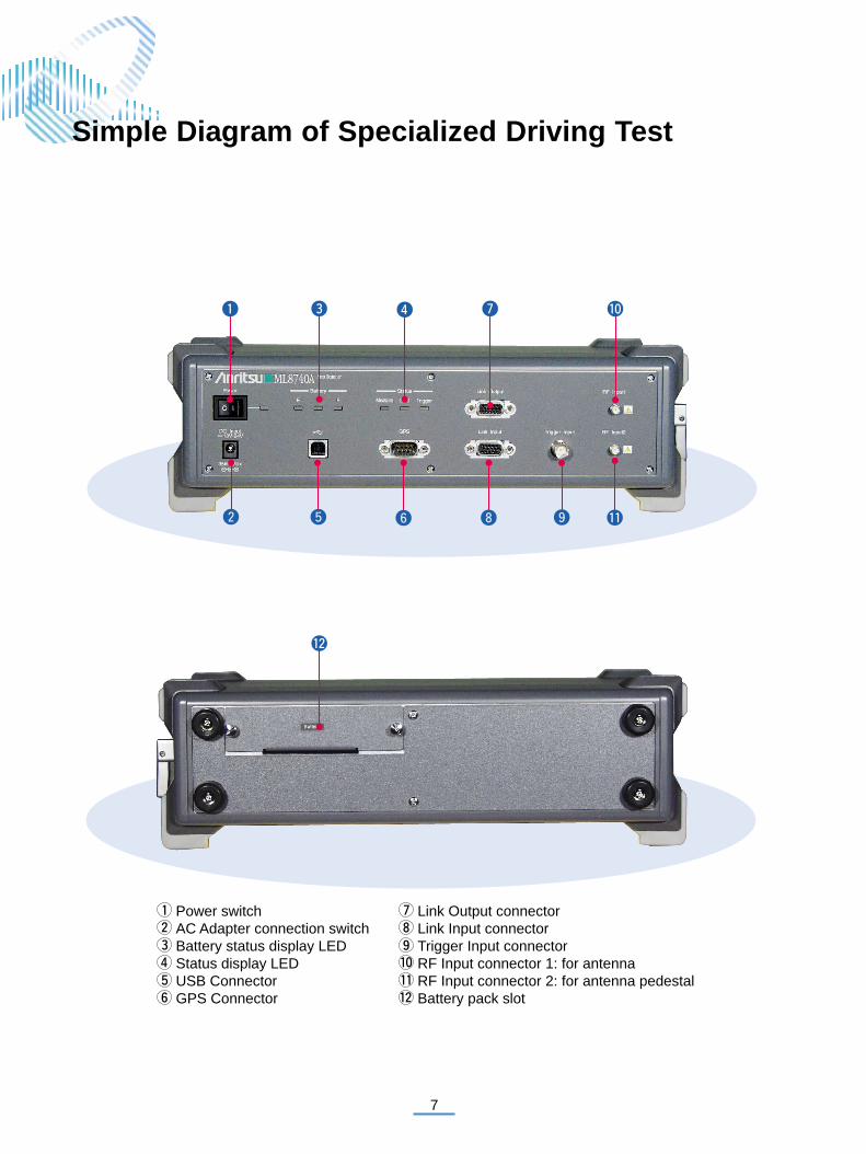
Power switch Link Output connectorAC Adapter connection switch Link Input connectorBattery status display LED Trigger Input connectorStatus display LED RF Input connector 1: for antennaUSB Connector RF Input connector 2: for antenna pedestalGPS Connector Battery pack slot
Simple Diagram of Specialized Driving Test
8
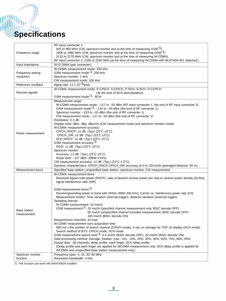
RF input connecter 1:925 to 960 MHz (CW, spectrum monitor and at the time of measuring GSM∗ 1)
Frequency range 1805 to 1880 MHz (CW, spectrum monitor and at the time of measuring GSM∗ 1)2110 to 2170 MHz (CW, spectrum monitor and at the time of measuring W-CDMA)
RF input connecter 2: 2100 to 2200 MHz (at the time of measuring W-CDMA with ML8740A-001 attached.)Input impedance 50 Ω (SMA type connecter)
W-CDMA measurement mode: 200 kHzFrequency setting GSM measurement mode∗ 1: 200 kHzresolution Spectrum monitor: 1 kHz
CW measurement mode: 100 kHzReference oscillator Aging rate: ±1 x 10⁻⁶/year
Receive signalsW-CDMA measurement mode: P-CPICH, S-CPICH, P-SCH, S-SCH, P-CCPCH
(At the time of BCH demodulation)GSM measurement mode∗ 1: BCHMeasurement range
W-CDMA measurement mode: –117 to –33 dBm (RF input connecter 1, the end of RF input connecter 2)GSM measurement mode∗ 1: –110 to –40 dBm (the end of RF connecter 1)Spectrum monitor: –123 to –33 dBm (the end of RF connecter 1)CW measurement mode: –117 to –33 dBm (the end of RF connecter 1)
Resolution: 0.1 dB Display units: dBm, dBµ, dBµV/m (CW measurement mode and spectrum monitor mode)W-CDMA measurement accuracy
CPICH_RSCP: ±1 dB (Typ.) (23˚C ±5˚C)Power measurement
CPICH_SIR: ±2 dB (Typ.) (23˚C ±5˚C)SCH_RSCP: ±2 dB (Typ.) (23˚C ±5˚C)
GSM measurement accuracy∗ 1
RSSI: ±1 dB (Typ.) (23˚C ±5˚C)Spectrum monitor
Accuracy: ±1 dB (Typ.) (23˚C ±5˚C)Noise level: –127 dBm (RBW 4 kHz)
CW measurement accuracy: ±1 dB (Typ.) (23°C ± 5°C)Dynamic characteristics: CPICH_RSCP, CPICH_SIR accuracy at 0 to 100 km/h (averaged distance: 50 m)
Measurement items Specified base station, unspecified base station, spectrum monitor, CW measurementW-CDMA measurement items
Received signal code power (RSCP), ratio of desired receive power per chip to receive power density (Ec/No), signal interference ratio (SIR)
GSM measurement items∗ 1
Receiving/sending power in band with (RSSI, RBW 200 kHz), Carrier vs. interference power rate (C/I) Measurement modes: Time variation (internal trigger), distance variation (external trigger)
Sampling intervalW-CDMA measurement: 10 ms/chGSM measurement∗ 1: 20 ms/ch (specified channel measurement only, BSIC decode OFF)
50 ms/ch (unspecified channel included measurement, BSIC decode OFF)100 ms/ch (BSIC decode ON)
Measurement channels: 32 max.W-CDMA measurement sync acquisition time:
600 ms x the number of search channel (CPICH mode), 4 sec on average for TOP 10 display (SCH mode)Search method of BTS: CPICH mode, SCH mode
GSM measurement search time∗ 1: 3.3 ms/ch (BSIC decode OFF), 20 ms/ch (BSIC decode ON)Data processing method: Average, median, max., min., 10%, 20%, 30%, 40%, 60%, 70%, 80%, 90%Output data : All channels, delay profile, each finger, SCH delay profile
(Delay profile and each finger are applied for WCDMA measurement only. SCH delay profile is applied for WCDMA and unspecified base station measurement only.)
Spectrum monitor Frequency span: 4, 10, 30, 60 MHzfunction Resolution bandwidth: 4 kHz
Specifications
Base station measurement
∗ 1: This function can work with MX874002A installed.
9
CW measurement Frequency setting resolution: 100 kHz, Resolution bandwidth: 15 kHzDemodulation channel: BCHDemodulation information:
MIB, SB1, SB2, SIB1, SIB2, SIB3, SIB4, SIB5, SIB6, SIB7, SIB8, SIB9, SIB10, SIB11, SIB12, SIB13, SIB13-1, SIB13-2,SIB13-3, SIB13-4, SIB14, SIB15, SIB15-1, SIB15-2, SIB15-3, SIB15-4, SIB15-5, SIB16, SIB17, SIB18
Demodulation functionWhen the demodulation function is enabled, MIB, SB1, SB2, and SIB7 are always demodulated, and others canbe selected for demodulation as desired. Although the uplink interference power (SIB7) is demodulated periodi-cally, the demodulation period varies depending on the setting and environmental conditions.
Demodulation processing time: 0,5 s (P-CCPCH 2 frame)Demodulation success rate: >50%, 70%(Typ.)
(P-CCPCH 2 frame, Ec/No ≥–14 dB, Dynamic response 0 to 100 km/h)Master/slave function: Daisy chain connection of multiple ML8740A, parallel measurementGPS connection: Supports NMEA-0183 formatRemote control: Via USBDiversity function: Transmit diversity, receive antenna diversity (Option 001)Two carrier measurement function: Two carrier frequencies can be measured
Other functionssimultaneously in the specified base station measurement and the unspecified base station measurement(Option 001)
RAKE diversity: Six fingersExternal trigger calibration:
Car speed pulse occurrence interval measurement and distance setting of measurement cycle are possible.External trigger input: 1.5 Vdc ± (2 to 13 Vp-p), BNC connectorSync output: TTL level, D-Sun connecter
InterfacePC : USB (Full Speed : 12 Mbps), Type B connecterGPS : RS-232C (38.4 kbps max.), D-Sub9P connecterTemperature and humidity: 0 to +40˚C/≤90% (operating), –40 to +80˚C/≤90% (storage)Vibration: MIL-T-28800E (Class 3)
Environment conditionsEMC
EN61326: 1997/A2: 2001 (Class A), EN61000-3-2: 2000 (Class A), EN61326: 1997/A2: 2001 (Annex A)LVD
EN61010-1: 2001 (PD2) DC : (rating) 10 to 24 V (Power tolerance : 8 to 26.4 V) AC : (rating): 100 to 240 V, 50/60 Hz, 50 VA max (with AC adapter)
Power Power Battery: Z0619 Lithium Ion Battery Pack (Sell separately)Power consumption: 35 W max. (battery charge), Standard: 15 W, 25 W (with Option 001)Battery continuous operation time: 5 h (typical), 3 h (typical with Option 001)
Dimensions and mass 320 (W) x 88 (H) x 231 ( D) mm, ≤3.5 kg, ≤4 kg (with Option 001)
10
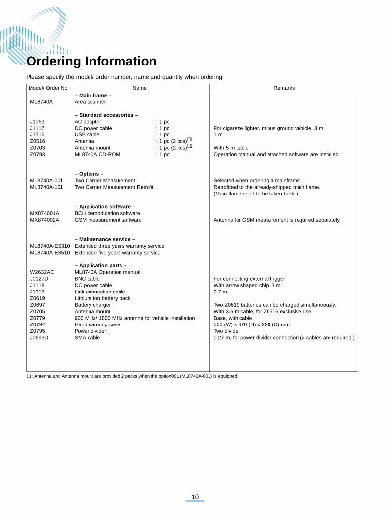
Model/ Order No. Name Remarks– Main frame –
ML8740A Area scanner
– Standard accessories –J1069 AC adapter : 1 pcJ1117 DC power cable : 1 pc For cigarette lighter, minus ground vehicle, 3 mJ1316 USB cable : 1 pc 1 mZ0516 Antenna : 1 pc (2 pcs)∗ 1
Z0703 Antenna mount : 1 pc (2 pcs)∗ 1 With 5 m cableZ0793 ML8740A CD-ROM : 1 pc Operation manual and attached software are installed.
– Options –ML8740A-001 Two Carrier Measurement Selected when ordering a mainframe.ML8740A-101 Two Carrier Measurement Retrofit Retrofitted to the already-shipped main flame.
(Main flame need to be taken back.)
– Application software –MX874001A BCH demodulation softwareMX874002A GSM measurement software Antenna for GSM measurement is required separately.
– Maintenance service –ML8740A-ES310 Extended three years warranty serviceML8740A-ES510 Extended five years warranty service
– Application parts –W2632AE ML8740A Operation manual J0127D BNC cable For connecting external triggerJ1118 DC power cable With arrow shaped chip, 3 mJ1317 Link connection cable 0.7 mZ0619 Lithium ion battery pack Z0697 Battery charger Two Z0619 batteries can be charged simultaneously.Z0705 Antenna mount With 3.5 m cable, for Z0516 exclusive useZ0779 900 MHz/ 1800 MHz antenna for vehicle installation Base, with cableZ0794 Hand carrying case 560 (W) x 370 (H) x 220 (D) mmZ0795 Power divider Two divideJ0693D SMA cable 0.27 m, for power divider connection (2 cables are required.)
Please specify the model/ order number, name and quantity when ordering.
∗ 1: Antenna and Antenna mount are provided 2 packs when the option001 (ML8740A-001) is equipped.
Ordering Information

11
ANRITSU CORPORATION1800 Onna, Atsugi-shi, Kanagawa, 243-8555 JapanPhone: +81-46-223-1111Fax: +81-46-296-1264
• U.S.A.ANRITSU COMPANYTX OFFICE SALES AND SERVICE1155 East Collins Blvd., Richardson, TX 75081, U.S.A.Toll Free: 1-800-ANRITSU (267-4878)Phone: +1-972-644-1777Fax: +1-972-644-3416
• CanadaANRITSU ELECTRONICS LTD.700 Silver Seven Road, Suite 120, Kanata, ON K2V 1C3, CanadaPhone: +1-613-591-2003 Fax: +1-613-591-1006
• Brasil ANRITSU ELETRÔNICA LTDA.Praca Amadeu Amaral, 27 - 1 andar01327-010 - Paraiso, Sao Paulo, BrazilPhone: +55-11-3283-2511Fax: +55-11-3886940
• U.K.ANRITSU LTD.200 Capability Green, Luton, Bedfordshire LU1 3LU, U.K.Phone: +44-1582-433280 Fax: +44-1582-731303
• GermanyANRITSU GmbHNemetschek Haus Konrad-Zuse-Platz 1 81829München, Germany Phone: +49 (0) 89 442308-0 Fax: +49 (0) 89 442308-55
• FranceANRITSU S.A.9, Avenue du Québec Z.A. de Courtabœuf 91951 LesUlis Cedex, France Phone: +33-1-60-92-15-50Fax: +33-1-64-46-10-65
• ItalyANRITSU S.p.A.Via Elio Vittorini, 129, 00144 Roma EUR, ItalyPhone: +39-06-509-9711 Fax: +39-06-502-2425
• SwedenANRITSU ABBorgafjordsgatan 13 164 40 Kista, SwedenPhone: +46-853470700 Fax: +46-853470730
• FinlandANRITSU ABTeknobulevardi 3-5, FI-01530 Vantaa, FinlandPhone: +358-9-4355-220Fax: +358-9-4355-2250
• DenmarkAnritsu AB DanmarkKorskildelund 6 DK - 2670 Greve, DenmarkPhone: +45-36915035Fax: +45-43909371
• SingaporeANRITSU PTE LTD.10, Hoe Chiang Road #07-01/02, Keppel Towers,Singapore 089315 Phone: +65-6282-2400 Fax: +65-6282-2533
• Hong Kong ANRITSU COMPANY LTD.Suite 923, 9/F., Chinachem Golden Plaza, 77 ModyRoad, Tsimshatsui East, Kowloon, Hong Kong, ChinaPhone: +852-2301-4980Fax: +852-2301-3545
• P. R. ChinaANRITSU COMPANY LTD.Beijing Representative OfficeRoom 1515, Beijing Fortune Building, No. 5 NorthRoad, the East 3rd Ring Road, Chao-Yang DistrictBeijing 100004, P.R. ChinaPhone: +86-10-6590-9230
• KoreaANRITSU CORPORATION8F Hyun Juk Bldg. 832-41, Yeoksam-dong, Kangnam-ku, Seoul, 135-080, KoreaPhone: +82-2-553-6603Fax: +82-2-553-6604
• AustraliaANRITSU PTY LTD.Unit 3/170 Forster Road Mt. Waverley, Victoria, 3149,AustraliaPhone: +61-3-9558-8177Fax: +61-3-9558-8255
• TaiwanANRITSU COMPANY INC.7F, No. 316, Sec. 1, NeiHu Rd., Taipei, TaiwanPhone: +886-2-8751-1816Fax: +886-2-8751-1817
Specifications are subject to change without notice.
Catalog No. ML8740A-E-A-1-(1.01) Printed in Japan 2005-10 ddc/CDT
050912
Printed on 70% Recycled Paper