
Area-efficient architectures for the Viterbi algorithm. I. Theory - … · Area-Efficient...
9
636 IEEE TRANSACTIONS ON COMMUNICATIONS, VOL. 41, NO. 4, APRIL 1993 Area-Efficient Architectures for the Viterbi Algorithm-Part I: Theory C. Bernard Shung, Horng-Dar Lin, Robert Cypher, Paul H. Siegel, and Hemant K. Thapar Abstract-The Viterbi algorithm has been widely applied to many decoding and estimation applications in communications and signal processing. A state-parallel implementation is usually used in which one add-compare-select (ACS) unit is devoted to each state in the trellis. In this paper we present a systema- tic approach of partitioning, scheduling, and mapping the N trellis states to P ACS’s, where N > P. The area saving of our architecture comes from the reduced number of both the ACS’s and interconnection wires. The design of the ACS, path metric storage, and routing network is discussed in detail. The proposed architecture creates internalparallelism due to the ACS sharing, which can be exploited to increase the throughput rate by pipelining. Consequently, the area-efficientarchitecture offers a favorable (smaller) area-time product, compared to a state- parallel implementation. These results will be demonstrated by application examples in the accompanying paper. I. INTRODUCTION HE Viterbi algorithm [8], [13] has been widely applied T to many decoding and estimation applications in com- munications and signal processing. It can be used to perform maximum likelihood decoding for convolutional codes, or maximum likelihood estimation of the transmitted sequence over a channel with intersymbol interference (ISI) [7]. Re- cently, it was also applied to hidden Markov model based continuous speech recognition [ 111. The Viterbi algorithm is defined in terms of a trellis dia- gram. In decoding, the algorithm attempts to reconstruct the actions of the encoder based on the transmission of its outputs over a noisy channel. Specifically, it assigns a value, called the path metric, to each node in the trellis. For each incoming branch, the path metric of the node from which the branch originated is added to a branch metric which gives the likelihood that the corresponding state transition occurred, based on the value received over the noisy channel. The sums calculated for each of the incoming branches are compared and the largest one (corresponding to the most likely transition) is selected.’ This selected sum is used as the new path metric Paper approved by the Editor for VLSI in Communications of the IEEE Communications Society. Manuscript received August 29, 1990; revised April 14, 1991. This paper was presented in part at the Global Telecommunications Conference, San Diego, CA, December 1990. C. B. Shung is with the Department of Electronics Engineering, National Chiao Tung University, Hsinchu, Taiwan, Republic of China. H. D. Lin is with AT&T Bell Laboratories, Holmdel, NJ, 07733. R. E. Cypher and P. H. Siegel are with the IBM Research Division, Almaden H. K. Thaper is with the IBM Storage Systems Products Division, San Jose, IEEE Log Number 9209473. ‘Alternately, The distance or inverse likelihood can used as metric. In this Research Center, San Jose, CA, 95120-6099. CA, xxxxx. case, the most likely transition corresponds to the smallest sum. for the node. The calculation of the path metrics is often implemented by an Add-Compare-Select (ACS) unit. Because of the feedback loop, the ACS is generally con- sidered to be the most critical part in the implementation of the Viterbi algorithm. Most implementations employ a state- parallel approach in which one ACS is devoted to each state in the trellis. The speed bottleneck in such implementations is the delay of the ACS. In continuous speech recognition in which the number of states is large and the sampling rate is low, a state-serial approach is often used. All the states share one (or a few) ACS sequentially. In this paper, we study the general problem of partitioning and scheduling the states in sharing the ACS’s. The proposed area-efficient architecture is shown to provide favorable area-time tradeoffs in practical examples. Several architectures have been proposed to address the speed/area tradeoff of the ACS. Fettweis and Meyr [3] (and, independently, Lin and Messerschmitt [ 101 and Thapar and Cioffi [12]) proposed a technique to trade area for speed, in which speed beyond the ACS bottleneck was achieved by using a parallel implementation that operates on the M-Step trellis. Gulak and Shwedyk [6] observed that the state-parallel implementation with a de Bruijn graph trellis results in an interconnection network defined by a shuffle-exchange graph. Based on the VLSI grid model, they applied the work on optimum layout of shuffle-exchange graphs to reduce the wiring area. Gulak and Kailath [SI proposed three types of locally connected processor arrays-cascade, linear, and mesh-for trellises with a de Bruijn graph structure. The idea was to further reduce wiring area by limiting each ACS to communicate only with its neighbors. In linear and mesh arrays, N ACS’s are required for a trellis of N states. In a cascade array, logN butterfly processors are required for a trellis of N states. However, each of the ZogN processors serves all N states in sequence with complex switches used among the processors for timing alignment. In this paper, we propose a new area-efficient architecture model that trades speed for area. One unique feature of our scheme is that each ACS is shared by a fixed subset of the states. The novelty of our architecture is best illustrated by the area-time diagram (AT diagram) in Fig. 1. The state-parallel implementation of a particular trellis corresponds to a fixed point in the AT diagram. It can be seen that the high-speed techniques [3], [lo], [12] and the area-efficient techniques can be used to explore the design space in two different directions. 0090-6778/93$03.00 0 1993 IEEE
Transcript of Area-efficient architectures for the Viterbi algorithm. I. Theory - … · Area-Efficient...

636 IEEE TRANSACTIONS ON COMMUNICATIONS, VOL. 41, NO. 4, APRIL 1993
Area-Efficient Architectures for the Viterbi Algorithm-Part I: Theory
C. Bernard Shung, Horng-Dar Lin, Robert Cypher, Paul H. Siegel, and Hemant K. Thapar
Abstract-The Viterbi algorithm has been widely applied to many decoding and estimation applications in communications and signal processing. A state-parallel implementation is usually used in which one add-compare-select (ACS) unit is devoted to each state in the trellis. In this paper we present a systema- tic approach of partitioning, scheduling, and mapping the N trellis states to P ACS’s, where N > P . The area saving of our architecture comes from the reduced number of both the ACS’s and interconnection wires. The design of the ACS, path metric storage, and routing network is discussed in detail. The proposed architecture creates internal parallelism due to the ACS sharing, which can be exploited to increase the throughput rate by pipelining. Consequently, the area-efficient architecture offers a favorable (smaller) area-time product, compared to a state- parallel implementation. These results will be demonstrated by application examples in the accompanying paper.
I. INTRODUCTION HE Viterbi algorithm [8], [13] has been widely applied T to many decoding and estimation applications in com-
munications and signal processing. It can be used to perform maximum likelihood decoding for convolutional codes, or maximum likelihood estimation of the transmitted sequence over a channel with intersymbol interference (ISI) [7]. Re- cently, it was also applied to hidden Markov model based continuous speech recognition [ 111.
The Viterbi algorithm is defined in terms of a trellis dia- gram. In decoding, the algorithm attempts to reconstruct the actions of the encoder based on the transmission of its outputs over a noisy channel. Specifically, it assigns a value, called the path metric, to each node in the trellis. For each incoming branch, the path metric of the node from which the branch originated is added to a branch metric which gives the likelihood that the corresponding state transition occurred, based on the value received over the noisy channel. The sums calculated for each of the incoming branches are compared and the largest one (corresponding to the most likely transition) is selected.’ This selected sum is used as the new path metric
Paper approved by the Editor for VLSI in Communications of the IEEE Communications Society. Manuscript received August 29, 1990; revised April 14, 1991. This paper was presented in part at the Global Telecommunications Conference, San Diego, CA, December 1990.
C. B. Shung is with the Department of Electronics Engineering, National Chiao Tung University, Hsinchu, Taiwan, Republic of China.
H. D. Lin is with AT&T Bell Laboratories, Holmdel, NJ, 07733. R. E. Cypher and P. H. Siegel are with the IBM Research Division, Almaden
H. K. Thaper is with the IBM Storage Systems Products Division, San Jose,
IEEE Log Number 9209473. ‘Alternately, The distance or inverse likelihood can used as metric. In this
Research Center, San Jose, CA, 95120-6099.
CA, xxxxx.
case, the most likely transition corresponds to the smallest sum.
for the node. The calculation of the path metrics is often implemented by an Add-Compare-Select (ACS) unit.
Because of the feedback loop, the ACS is generally con- sidered to be the most critical part in the implementation of the Viterbi algorithm. Most implementations employ a state- parallel approach in which one ACS is devoted to each state in the trellis. The speed bottleneck in such implementations is the delay of the ACS. In continuous speech recognition in which the number of states is large and the sampling rate is low, a state-serial approach is often used. All the states share one (or a few) ACS sequentially. In this paper, we study the general problem of partitioning and scheduling the states in sharing the ACS’s. The proposed area-efficient architecture is shown to provide favorable area-time tradeoffs in practical examples.
Several architectures have been proposed to address the speed/area tradeoff of the ACS. Fettweis and Meyr [3] (and, independently, Lin and Messerschmitt [ 101 and Thapar and Cioffi [12]) proposed a technique to trade area for speed, in which speed beyond the ACS bottleneck was achieved by using a parallel implementation that operates on the M-Step trellis. Gulak and Shwedyk [6] observed that the state-parallel implementation with a de Bruijn graph trellis results in an interconnection network defined by a shuffle-exchange graph. Based on the VLSI grid model, they applied the work on optimum layout of shuffle-exchange graphs to reduce the wiring area. Gulak and Kailath [SI proposed three types of locally connected processor arrays-cascade, linear, and mesh-for trellises with a de Bruijn graph structure. The idea was to further reduce wiring area by limiting each ACS to communicate only with its neighbors. In linear and mesh arrays, N ACS’s are required for a trellis of N states. In a cascade array, logN butterfly processors are required for a trellis of N states. However, each of the ZogN processors serves all N states in sequence with complex switches used among the processors for timing alignment.
In this paper, we propose a new area-efficient architecture model that trades speed for area. One unique feature of our scheme is that each ACS is shared by a fixed subset of the states. The novelty of our architecture is best illustrated by the area-time diagram (AT diagram) in Fig. 1. The state-parallel implementation of a particular trellis corresponds to a fixed point in the AT diagram. It can be seen that the high-speed techniques [3], [lo], [12] and the area-efficient techniques can be used to explore the design space in two different directions.
0090-6778/93$03.00 0 1993 IEEE

SHUNG et al.: AREA-EFFICIENT ARCHITECTURES FOR THE VITERBI ALGORITHM-PART I: THEORY 637
Area , High-speed technique
! results in area overhead AT=mnst 1%
Time
Fig. 1. Area-time (AT) diagram. AT = const is used as the reference line. The area-efficient technique (solid curve) can be used to trade speed for area saving, while the high-speed technique (dashed curve) can be used to trade area for speed. Comparing with the reference, it can be seen that the area-efficient technique improves throughput, while the high-speed technique results in area overhead.
We choose A T = constant to be the reference curve.’ The complexity of the M-step ACS in [3] introduces area overhead in the high-speed techniques. On the other hand, our area- efficient techniques provide throughput increase, by virtue of the introduction of internal parallelism. Furthermore, the area-efficient techniques based on locally connected processor arrays [5] suggest discrete design choices in the AT diagram. On the contrary, our technique provides a continuous means of trading speed for area. It is therefore easier to find an optimal design solution for particular area or speed constraints.
The paper is organized as follows. In Section 11, we intro- duce our area-efficient architecture model. We define several criteria that we use in the paper to evaluate the architecture. In Section 111, trellis partitioning and scheduling are described. In Section IV, we discuss the design of the local memory where the path metrics are stored. Design techniques to achieve higher throughput rate with a pipelined ACS are discussed in Section V. The area-time analysis is provided in Section VI. Applications examples of the area-efficient architectures will be shown in the accompanying paper.
11. ARCHITECTURAL MODEL FOR AREA-EFFICIENT IMPLEMENTATION
Fig. 2 illustrates our architectural model for area-efficient implementation of the Viterbi algorithm. It consists of P ACS’s with associated local memories and a routing network. We assume that the N trellis states are evenly partitioned into the P ACS’s, where P divides N.3 We call the implementation time-efficient if no ACS is idle at any time, so it takes ( N I P ) time units to finish all N trellis states. We define the i- degree, d; , of a trellis state as the number of incoming edges
21n Fig. 1, both area and time axes are in a logarithmic scale, therefore, AT = constant is represented by a straight line.
’If P does not divide N , then P [ N / P ] - N ACS’s will be idle in one of [NIP1 time units, assuming one time unit is required for one ACS to process one state.
I I - - I
I Y Acs2 MEZH I -- I I ‘ 1
Fig. 2. The architecture model for the area-efficient implementation.
to that state. We define the 0-degree, do, of a trellis state as the number of outgoing edges from that state. We call a trellis homogeneous if for all states, di = do = d, and we call d the degree of the trellis. We will concentrate on homogeneous trellises, as nonhomogeneous trellises can be made homogeneous by adding dummy branches.
The local memory of each ACS is divided into two banks-one storing the ( d N / P ) old path metrics (the inputs to the ACS), and the other storing the ( N I P ) new path metrics (the outputs of the ACS). The two local memory banks are referred to as the input local memory and the output local memory. The input local memory has d read ports and d write ports, and the output local memory has d read ports and 1 write port. In Section V, we will discuss alternative design techniques for the local memories to avoid the need for multiport memories.
For a homogeneous trellis of N states and degree d, the P ACS’s together require Pd old path metrics at any one time. We are interested in finding an implementation in which the Pd old path metrics which enter the routing network at a given time are evenly distributed among the P local memories. In such a case, only d wires are required from each local memory to the routing network. We call such a design bandwidth- efficient as the bandwidth of the routing network is reduced from Nd (in a state-parallel implementation) to Pd.
In a bandwidth-efficient implementation, the routing net- work routes Pd old path metrics to the input local memory of the P ACS’s at each time unit. In general, the required routing (permutation) is different in each time unit, and hence a dynamic routing network has to be used. We will discuss the use of a multistage interconnection network (MIN) [14] in this case. If the required routing is the same in each time unit, the routing network degenerates to Pd wires. We call this the jixed-interconnection case. In Section IV, we discuss partitioning and scheduling techniques for both fixed- interconnection and MIN routing networks.
Based on the architectural model, the goal is to find a time-efficient and bandwidth-efficient implementation for a

638 IEEE l"SACXI0NS ON COMMUNICATIONS, VOL. 41, NO. 4, APRIL 1993
particular trellis diagram. It will be shown in Section IV that bandwidth-efficiency can always be achieved by our partition- ing, scheduling, and architecture mapping techniques. It will be shown in Section VI that time efficiency can always be achieved if interleaved independent data sources are allowed. We will also show that the sharing of an ACS allows additional pipelining of the states which can be exploited to improve the throughput rate. This, plus the area reduction enabled by reducing the number of ACS's and interconnections, produces a favorable area-time tradeoff for the proposed architecture. Fig. 3. A 6-state degree-2 trellis for Example 1.
111. TRELLIS PARTITIONING AND SCHEDULING
In this section we discuss how to partition the N trellis states into P ACS's and schedule the ( N I P ) states within each ACS, where P is chosen depending upon the amount of area saving desired. We will begin by assuming the existence of a MIN routing network, and we will show that any trellis can be implemented in a bandwidth-efficient manner. We will then give the criterion which a trellis must meet in order for the MIN routing network to be replaced by a fixed-interconnection network.
A. Partitioning, Scheduling, and Communication Requirements The partitioning of the N trellis states into the P ACS's,
and the scheduling of the (NIP) states within each ACS, have a major impact on the design of the routing network and the ACS local memories. The matrix S = { s i j } will represent the partitioning and scheduling of the trellis states. Specifically, let s i j be the state that is assigned to the ith ACS and scheduled to be processed at the j th time unit, 0 5 i < P, 0 5 j < ( N I P ) .
Given the partitioning and scheduling matrix S and the trel- lis which is being used, we can define two additional matrices, X and Y, which capture the communication requirements. Matrix X is the Pd-by-(NIP) matrix created by making d copies of each row of S. Specifically, xij = S k j , where IC = Li/d]. Thus, if d copies are made of each ACS output, xi j represents the ith output from the array of ACS's at the j th time unit. Matrix Y is the Pd-by-(NIP) matrix created by replacing each entry s i j E S with a column of d entries giving the d old path metrics which are needed in order to calculate si?. Specifically, {yij I Li/d_l = IC} is the set of d old path metrics that are needed to calculate the new path metric for state s k j . Thus, yij represents the ith input that is required by the array of ACS's at the j th time unit.
Example 1: A 6-state degree-2 homogeneous trellis is shown in Fig. 3. The S , X, and Y matrices of a particular partitioning and scheduling are shown below.
0 4 2
s = ( ; ; ;) .=(; ; ;)
y j 5 2 0 4 ' 1)
3 1 5 0 4 2
3 1 5
Because the outputs of the array of ACS's are created in the pattern defined by X, and the inputs to the array of ACS's are required in the pattern defined by Y , the architecture must support the mapping of the matrix X into the matrix Y. A permutation which accomplishes this mapping from X to Y will be called a matrix permutation for the given trellis. This matrix permutation will be implemented in the routing network and/or the local memories of the ACS's.
The next subsection presents a general technique for divid- ing a matrix permutation into a number of smaller, independent permutations. This general technique will then be used to obtain a bandwidth-efficient implementation of an arbitrary matrix permutation on our architectural model. Therefore, an arbitrary partitioning and scheduling matrix S can be chosen. However, we will show later that the choice of S in a fixed- interconnection implementation can be difficult.
B. Matrix Permutations
In this subsection we will show that any matrix permutation can be divided into three successive permutations-the first and third of which only rearrange elements within rows, and the second of which only rearranges elements within columns. We will need the following definitions.
Definitions: M is the set of Pd-by-(NIP) matrix permu- tations. Thus, each member of M is a function which takes as input a Pd-by-(NIP) matrix, and creates as output another Pd-by-(NIP) matrix which is obtained by rearranging the elements of the input matrix. R is the set of matrix within- rows-permutations, and C is the set of matrix within-columns- permutations. Thus, each member of R ( C ) is a function which takes as input a Pd-by-(NIP) matrix, and creates as output another Pd-by-( N / P ) matrix which is obtained by rearranging the elements in each row (column) of the input matrix. The permutation obtained by applying permutation A1 and then applying permutation A2 will be denoted A2 o A I .
The following theorem is due to Benes [l]. Theorem 1: For each permutation M E M , there exist
permutations AI, A2, and A3 such that A I E R, A2 E C, A3 E R, and M E A3 o A2 o A I .
Example 2: Here is a simple 4-by-4 example of Theorem 1. The permutation can be defined by a matrix of numbers from 0 through 15 giving the destination of each item. The input matrix I and the output matrix 0 are
SHUNG et aL: AREA-EFFICIENT ARCHITECTURES FOR THE VITERBI ALGORITHM-PART I: THEORY 639
/ 1 13 2 6 \ / o 1 2 3 \
I = [ ; 9 11 0 15 8 12 3 J O = ( ; l"o 7 14 4 12 13 14 15
The required matrix permutation can be decomposed as fol- lows, where A1 and AJ are within-rows-permutations and A2 is a within-columns-permutation:
/ 6 13 1 2 \
/ 3 0 1 2 \
\ 1 4 13 12 15) / o 1 2 3 \
\ 1 2 13 14 1 5 1
C. MIN Implementation
In this subsection we will describe a general architecture that provides a bandwidth-efficient implementation for any homo- geneous trellis. Given the trellis, first select any matrix per- mutation for the trellis. This matrix permutation will permute the items in a Pd-by-(NIP) matrix. Next, use Theorem 1 to divide the matrix permutation into a within-rows-permutation, followed by a within-columns-permutation, followed by a within-rows-permutation. This division of the matrix permu- tation can be found in O(Ndlog(Nd) log(N/P)) time on a sequential computer or in O(log2(Nd) log(N/P)) time on a shared memory parallel computer with Nd processors [9]. Then, use random-access memory for both banks of each ACS's local memory. This allows both within-rows- permutations to be performed by simply using the correct addressing patterns.
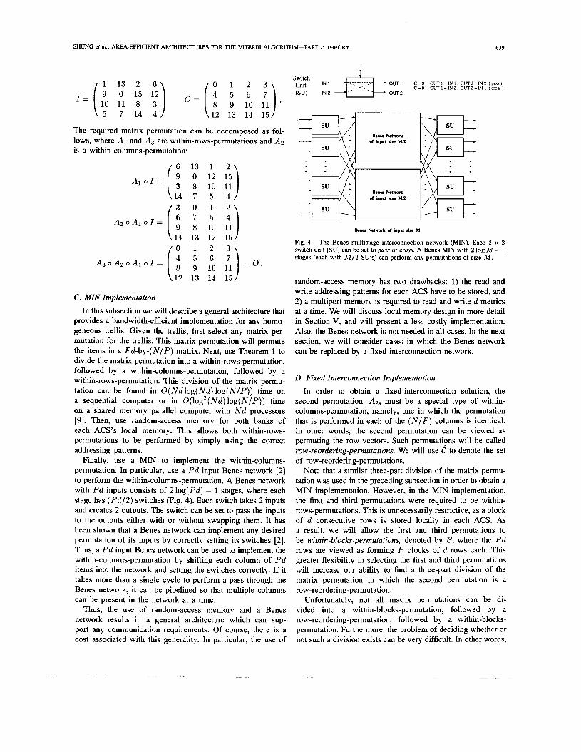
Finally, use a MIN to implement the within-columns- permutation. In particular, use a P d input Benes network [2] to perform the within-columns-permutation. A Benes network with P d inputs consists of 2log(Pd) - 1 stages, where each stage has (Pd/2) switches (Fig. 4). Each switch takes 2 inputs and creates 2 outputs. The switch can be set to pass the inputs to the outputs either with or without swapping them. It has been shown that a Benes network can implement any desired permutation of its inputs by correctly setting its switches [2 ] . Thus, a P d input Benes network can be used to implement the within-columns-permutation by shifting each column of P d items into the network and setting the switches correctly. If it takes more than a single cycle to perform a pass through the Benes network, it can be pipelined so that multiple columns can be present in the network at a time.
Thus, the use of random-access memory and a Benes network results in a general architecture which can sup- port any communication requirements. Of course, there is a cost associated with this generality. In particular, the use of
Switch Unit I N 1 4-E ........................ OUT1 C = O : O U T I = I N I . O U T Z = I N 2 (pass) C = O : O U T I = I N 2 . O U T Z = I N I (cross)
OUT 2 (su) IN2 ,.::: ..... ::..
- IY I
Bem Network of lapnt she M
Fig. 4. The Benes multistage interconnection network (MIN). Each 2 x 2 switch unit (SU) can be set to puss or cross. A Benes MIN with 2 log M - 1 stages (each with M / 2 SU's) can perform any permutations of s u e M .
random-access memory has two drawbacks: 1) the read and write addressing patterns for each ACS have to be stored, and 2) a multiport memory is required to read and write d metrics at a time. We will discuss local memory design in more detail in Section V, and will present a less costly implementation. Also, the Benes network is not needed in all cases. In the next section, we will consider cases in which the Benes network can be replaced by a fixed-interconnection network.
D. Fixed Interconnection Implementation In order to obtain a fixed-interconnection solution, the
second permutation, A2, must be a special type of within- columns-permutation, namely, one in which the permutation that is performed in each of the ( N I P ) columns is identical. In other words, the second permutation can be viewed as permuting the row vectors. Such permutations will be called row-reordering-permutations. We will use C to denote the set of row-reordering-permutations.
Note that a similar three-part division of the matrix permu- tation was used in the preceding subsection in order to obtain a MIN implementation. However, in the MIN implementation, the first, and third permutations were required to be within- rows-permutations. This is unnecessarily restrictive, as a block of d consecutive rows is stored locally in each ACS. As a result, we will allow the first and third permutations to be within-blocks-permutations, denoted by B, where the P d rows are viewed as forming P blocks of d rows each. This greater flexibility in selecting the first and third permutations will increase our ability to find a three-part division of the matrix permutation in which the second permutation is a row-reordering-permutation.
Unfortunately, not all matrix permutations can be di- vided into a within-blocks-permutation, followed by a row-reordering-permutation, followed by a within-blocks- permutation. Furthermore, the problem of deciding whether or not such a division exists can be very difficult. In other words,
640 IEEE TRANSACTIONS ON COMMUNICATIONS, VOL. 41, NO. 4, APRIL 1993
‘I
, 5 1 ~, , i & ~ W 1 ~ , , 7 4 5‘ ~
IN {*k OUT SEU1 SEU I SEU 0 SEUz SEU M/2
( b) (a)
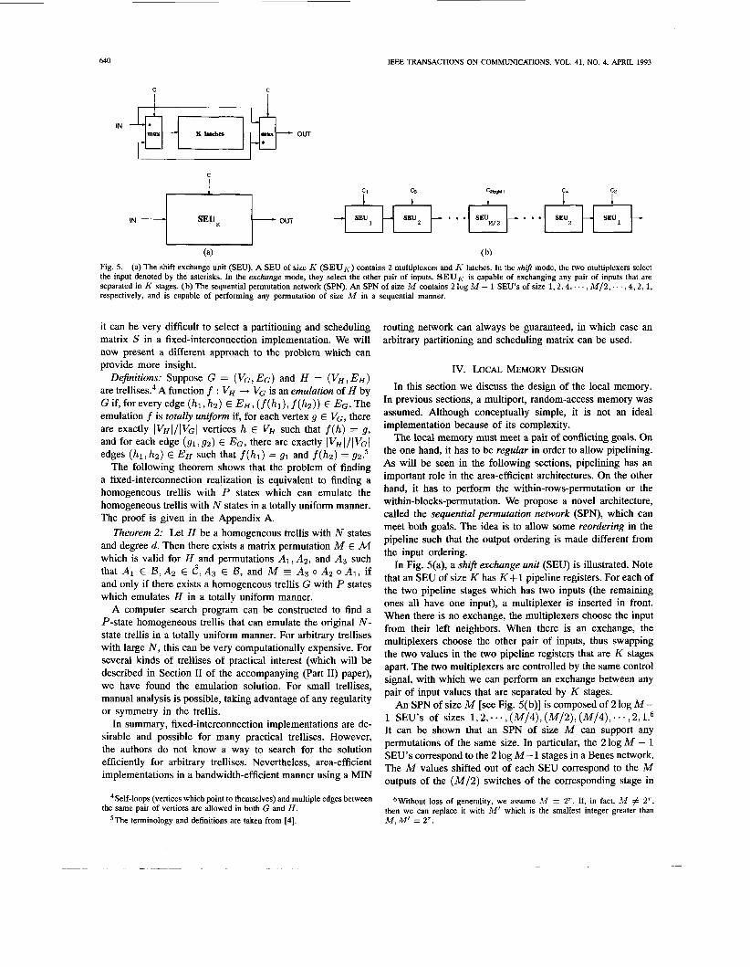
Fig. 5. (a) The shift exchange unit (SEU). A SEU of size K (SEUK) contains 2 multiplexers and h- latches. In the shift mode, the two multiplexers select the input denoted by the asterisks. In the exchange mode, they select the other pair of inputs. SEUK is capable of exchanging any pair of inputs that are separated in h’ stages. (b) The sequential permutation network (SPN). An SPN of size M contains 2 log M - 1 SEU’s of size 1 , 2 , 4 , . . . , M / 2 , . . . , 4 , 2 , 1 , respectively, and is capable of performing any permutation of size M in a sequential manner.
it can be very difficult to select a partitioning and scheduling matrix S in a fixed-interconnection implementation. We will now present a different approach to the problem which can provide more insight.
Definitions: Suppose G = (VG, E G ) and H = ( V H , EH) are t re l l i se~ .~ A function f : VH -+ VG is an emulation of H by G if, for every edge (hl, h ~ ) E E H , (f(hl), f (h2)) E EG. The emulation f is totally uniform if, for each vertex g E VG, there are exactly IVH I/~VG I vertices h E VH such that f (h) = g, and for each edge (g1,gZ) E EG, there are exactly \ V H ~ / ~ V G ~ edges (h l , hz) E EH such that f ( h l ) = g1 and f(hz) = 92.’
The following theorem shows that the problem of finding a fixed-interconnection realization is equivalent to finding a homogeneous trellis with P states which can emulate the homogeneous trellis with N states in a totally uniform manner. The proof is given in the Appendix A.
Theorem 2: Let H be a homogeneous trellis with N states and degree d. Then there exists a matrix permutation M E M which is valid for HAand permutations AI, Az, and A3 such that AI E B,Az E C,A3 E B, and M A3 o A2 o AI, if and only if there exists a homogeneous trellis G with P states which emulates H in a totally uniform manner.
A computer search program can be constructed to find a P-state homogeneous trellis that can emulate the original N- state trellis in a totally uniform manner. For arbitrary trellises with large N, this can be very computationally expensive. For several kinds of trellises of practical interest (which will be described in Section I1 of the accompanying (Part 11) paper), we have found the emulation solution. For small trellises, manual analysis is possible, taking advantage of any regularity or symmetry in the trellis.
In summary, fixed-interconnection implementations are de- sirable and possible for many practical trellises. However, the authors do not know a way to search for the solution efficiently for arbitrary trellises. Nevertheless, area-efficient implementations in a bandwidth-efficient manner using a MIN
Self-loops (vertices which point to themselves) and multiple edges between the same pair of vertices are allowed in both G and H .
5The terminology and definitions are taken from [4].
routing network can always be guaranteed, in which case an arbitrary partitioning and scheduling matrix can be used.
IV. LOCAL MEMORY DESIGN
In this section we discuss the design of the local memory. In previous sections, a multiport, random-access memory was assumed. Although conceptually simple, it is not an ideal implementation because of its complexity.
The local memory must meet a pair of conflicting goals. On the one hand, it has to be regular in order to allow pipelining. As will be seen in the following sections, pipelining has an important role in the area-efficient architectures. On the other hand, it has to perform the within-rows-permutation or the within-blocks-permutation. We propose a novel architecture, called the sequential permutation network (SPN), which can meet both goals. The idea is to allow some reordering in the pipeline such that the output ordering is made different from the input ordering.
In Fig. 5(a), a shift exchange unit (SEU) is illustrated. Note that an SEU of size K has K + 1 pipeline registers. For each of the two pipeline stages which has two inputs (the remaining ones all have one input), a multiplexer is inserted in front. When there is no exchange, the multiplexers choose the input from their left neighbors. When there is an exchange, the multiplexers choose the other pair of inputs, thus swapping the two values in the two pipeline registers that are K stages apart. The two multiplexers are controlled by the same control signal, with which we can perform an exchange between any pair of input values that are separated by K stages.
An SPN of size M [see Fig. 5( b)] is composed of 2 log M- 1 SEU’s of sizes 1,2,~~~,(M/4),(M/2),(M/4),~~~,2,1.6 It can be shown that an SPN of size M can support any permutations of the same size. In particular, the 2 log M - 1 SEU’s correspond to the 2 log M- 1 stages in a Benes network. The M values shifted out of each SEU correspond to the M outputs of the ( M / 2 ) switches of the corresponding stage in
6Without loss of generality, we assume M = 2‘. If, in fact, M # 2‘, then we can replace it with M’ which is the smallest integer greater than M , M’ = 2’.
SHUNG et al.: AREA-EFFICIENT ARCHITECTURES FOR THE VITERBI ALGORITHM-PART I: THEORY 641
the Benes network. Therefore, we can view the SPN as a sequential Benes network.’
Within-row-permutations can be implemented by SPN’s directly. The input and output local memories associated with each ACS require d SPN’s of size ( N I P ) . The d SPN’s of the output local memory all take as input the output of the corresponding ACS. Within-blocks-permutations, on the other hand, can be implemented by a combination of SPN’s and MIN’s. To see this, recall that a within-blocks-permutation is also a matrix permutation of size d by ( N I P ) . Therefore, it can be implemented by 2 MIN’s of size d and d SPN’s of size
There are two other advantages to implementing a pipelined local memory with an SPN. First, the circuit between any two pipeline stages is very simple (at most a multiplexer), and hence will not constitute the timing bottleneck in the pipeline. Second, note that the signall wires do not intersect, and hence the layout of an SPN is straightforward and compact.
One drawback of the SPN is its length, or latency, which is
3 K + 1 = - M + 2 l o g M - 1 21 ; M . c 2
K = 1 , 2 , 4 , . . . , ~ , . . . , 4 , 2 , 1
However, for particular codes, the within-rows-permutations often can be implemented with a special-purpose SPN with a considerably smaller length. Moreover, the within-blocks- permutations can sometimes be simplified to use one SPN with multiple tap points. These simplifications will be shown to be effective in the accompanying paper.
V. ACS PIPELINING In the previous two sections, we have seen that the SPN
and MIN can introduce significant latency. In this section, we consider the use of ACS pipelining to combat the latency problem.
Pipelining the ACS’s has been proposed to increase the throughput rate by interleaving a number of independent data sources. In this case, the parallelism can be thought of as being externally created, so we will call it external parallelism. As mentioned earlier, when the channel has memory or intersymbol interference, the external parallelism is no longer applicable. In our architecture model, however, additional parallelism is created internally by allowing several trellis states to share an ACS. We call this internal parallelism. Therefore, even when the channel has memory or intersymbol interference, in an area-efficient design ACS pipelining can still be applied to take advantage of the internal parallelism. On the other hand, if the channel is memoryless, the internal parallelism can be exploited in additional to the external parallelism. ACS pipelining exploiting the internal parallelism
7We choose not to call an SPN a sequential Benes network because 1) at each stage the SEU can manipulate a value more than once due to its sequential nature, and 2) the architecture of an SPN can support other types of MIN’s [14].
*From Theorem 1 it is obvious that there exists another decomposition in which A1 and AB are within-columns-permutations, and A2 is a within- rows-permutation. This decomposition is less costly for the within-blocks- permutation because d < (N/P).
is the key reason for the favorable area-time tradeoff in our area-efficient architectures.
The ACS for a degree-d trellis contains d adders and d - 1 comparators and selectors. Compared to the multiplexers in an SPN or the switches in the MIN, the ACS is more complex and hence can accommodate more pipeline stages. Even though adding pipeline stages in the ACS increases the total latency in the feedback loop, this effect is additive, while the speedup effect by pipelining is multiplicative. Therefore, the overall effect of ACS pipelining is positive. We will show in the next section that it is advantageous to have as many ACS pipeline stages as possible. However, we cannot put too many such that the pipeline delays within the ACS are smaller than those in the SPN and the MIN. Consequently, the optimal ACS pipelining is achieved when the pipeline delays within the ACS are equal to those in the SPN and MIN.
VI. AREA-TIME ANALYSIS
With ( N / P ) states sharing one ACS, a linear scale solution demands that the speed of the area-efficient architecture be ( N I P ) times slower. In this section, we will show that, with the help of ACS pipelining, our area-efficient architecture can achieve a throughput rate which is higher than that of a linear scale solution. In other words, the area-efficient technique not only allows the exploration of the design space by trading speed for area saving, but also achieves a smaller area-time product than the state-parallel implementation.
be the total number of pipeline stages in the SPN and MIN, and y be a overhead factor. The condition for our area-efficient architecture to perform better than the linear scale solution is
Let (Y be the number of pipeline stages in the ACS,
(1) f f + P < 1 N
a l + y P ‘ The numerator on the left-hand side of ( 1 ) indicates the total number of pipeline stages (latency) in the feedback loop. The left-hand side of ( 1 ) indicates the effective slow-down of the area-efficient architecture, compared to a nonpipelined state- parallel implementation. The right-hand side of ( 1 ) indicates the effective area saving. Equation (1) means that if the effective slow-down is smaller than the effective area saving, then the area-time tradeoff is favorable for the area-efficient architecture.
Both p and y are trellis dependent. Let p = ,& + ,&, where is the number of pipeline stages in the SPN and p2 is the number of pipeline stages in the MIN. For arbitrary codes ,& = S ( N / P ) , & = 210g Pd - 1 . For specific codes, however, the routing latency can be substantially smaller with special-purpose SPN’s. The y factor is to account for the overhead related to the routing network, pipeline registers, etc., which depends strongly on the particular codes. Note that the reduced number of interconnection wires (bandwidth- efficiency) contributes to the area saving and also partially compensates the overhead.
Note that a + p 2 ( N I P ) because each ACS needs at least ( N I P ) stages to store the path metrics of all the states sharing it. The excessive pipeline stages (of size (Y + p - ( N I P ) ) are so-called pipeline bubbles which render the architecture
642 IEEE TRANSACTIONS ON COMMUNICATIONS, VOL. 41, NO. 4, APRIL 1993
time-inefficient.’ Fortunately, the internal parallelism can be exploited to speedup the architecture by a factor of a. From the above equation, it is clear that the ACS pipelining has an additive effect on the total latency and a multiplicative effect on the throughput. Hence, it is advantageous to have cy as large as possible. On the other hand, as explained in the previous section, CY is also constrained by the fact that the pipeline delays in the ACS cannot be smaller than those in SPN and MIN. Therefore, the optimum CY (denoted by 5) occurs when the pipeline delay in the ACS is the same as the rest of the architecture (SPN and MIN).
VII. CONCLUSION In this paper, we propose a new class of area-efficient
architectures for the Viterbi algorithm that allows a number of trellis states to share one ACS. A systematic approach for partitioning, scheduling, and mapping the N trellis states to P ACS’s is presented. Based on the matrix permutation techniques, the partition and schedule of the trellis can be mapped to an area-efficient architecture with a multistage interconnection network (MIN). For trellises where emulation by a smaller trellis is possible, further area saving can be achieved with a fixed-interconnection realization.
We proposed a novel technique for path metric storage, by using a sequential permutation network (SPN) to reorder the path metrics. This technique results in a pipelined local memory which is faster and smaller than a multiport imple- mentation.
A major advantage of our area-efficient architectures is the internal parallelism, which is created by ACS sharing. Pipelin- ing the SPN and MIN introduces latency to the architecture, but pipelining the ACS is found to be an effective way to combat the latency problem. Detailed area-time analysis of our architectures is provided.
The favorable area-time tradeoff will be demonstrated by application examples in an accompanying paper. These include convolutional codes, matched-spectral-null (MSN) codes, and Ungerboeck codes. Applications to trellises with very large numbers of states and time-varying codes will also be dis- cussed. The area-efficient architecture also makes it possible to design a programmable Viterbi decoder due to the extensive amount of programmability in the SPN and MIN.
APPENDIX A PROOF OF THEOREM 2
Theorem 2: Let H be a homogeneous trellis with N states and degree d. Then there exists a matrix permutation M E M which is valid for H,-and permutations A l , A2, and A3 such that A1 E B,A2 E C,A3 E B, and M = A3 o A2 o A I , if and only if there exists a homogeneous trellis G with P states which emulates H in a totally uniform manner.
Proof: First we will assume that G exists, and we will show that suitable permutations AI ,,A2, and A3 must exist. Number the vertices in G with 0 through P - 1. Because G emulates H in a totally uniform manner, there exists a
9 0 f course, if external parallelism is applicable, then the pipeline bubbles can be eliminated, and the area-efficient architecture will be time-efficient.
mapping f which sends ( N I P ) vertices in H to each vertex in G, and ( N I P ) edges in H to each edge in G. We will use this mapping function f to create the matrix permutations M , A l , A 2 , and A3.
Label each vertex in H with a pair of the form [ i , j ] , O 5 i < P.0 5 j < ( N / P ) , indicating that it is the j th vertex in H which f maps to vertex i in G. Define a partitioning and scheduling matrix S (see Section 111-A), such that sij = [ i , j ] for all i and j , 0 5 i < P, 0 5 i < ( N / P ) . Create the matrix X by forming d copies of each row in S (see Section 111- A). Thus, for all i and j , 0 5 i < Pd,O 5 j < ( N / P ) , xij = [ Li/dJ, j ] . Create the matrix Y by replacing each entry s,j with a column of d entries giving the d old path metrics which are needed in order to calculate s i j (see Section 111-A). Specifically, for all i and j , 0 5 i < Pd,O 5 j < ( N / P ) , y i j = [a , b] if the (i mod 4 t h incoming edge to node [ l i / dJ , j ] in H comes from node [a, b] in H . Finally, let M be a matrix permutation defined by X and Y.
We will now show how M can be decomposed into per- mutations A l , A 2 , and A3 of the desired types. Label each edge in H with a triple of the form ( i , j , k ) , 0 5 i < P, 0 5 j < d,O 5 k < ( N / P ) , indicating that it is the kth edge in H which f maps to the j th outgoing edge from node i in G. Note that the outgoing edges leaving any node [a , b] in H have labels of the form ( a , j , k ) , because f maps the node [a , b] to node a in G, and f maps all of the edges which leave [a , b] to edges which leave a. Permutation A1 is defined to send each item xTc, 0 5 r < Pd, 0 5 c < ( N / P ) , to row id + j and column k if the (r mod d)th outgoing edge of node [ [ r / d J , c] is labeled { i , j , k ) . It was just shown that Lr/d] must equal i , so each item will remain within the same block of d rows, and A I E B.
Permutation A2 permutes the rows according to the pattern of connections in G. More formally, permutation A2 sends each item in row r and column c to row i d + j and column c if the (r mod d)th outgoing edge from node Lr/dJ in G is also the j th incoming edge to node i in G. It is clear that A2 keeps the same set of items in each column, and that items which start in the sameA row are sent by A2 to the same destination
The definition of permutation A3 is similar to the definition of permutation A I , except that it is stated in terms of incoming edges rather than outgoing edges. Label each edge in H with a triple of the form ( i , j , k ) , 0 5 i < P,O 5 j < d,O 5 k < ( N / P ) , indicating that it is the kth edge in H which f maps to the j th incoming edge to node i in G. Note that the incoming edges entering any node [a, b] in H have labels of the form ( a , j , k ) , because f maps the node [a,b] to node a in G, and f maps all of the edges which enter [a , b] to edges which enter a. Permutation A3 is defined to send each item from row T and column c, 0 5 r < Pd,O 5 c < ( N / P ) , to row i d + j and column k it the j th incoming edge to node [ i , k ] is labeled (a,b,c), where a = Lr/dJ and b = r mod d. It was just shown that [r/dJ must equal i , so each item will remain within the same block of d rows, and A3 E B.
It has been shown that A I E D,A2 E C , and A3 E B, but it still remains to be shown that M G A3 o A2 0 A I . Consider an arbitrary item in row i d + j and column k of
TOW, SO A2 E C.
SHUNG et al.: AREA-EFFICIENT ARCHITECTURES FOR THE VITERBI ALGORITHM-PART I: THEORY 643
x, where 0 5 i < P,o 5 j < d, and 0 5 k < ( N / P ) . From the definition of X , this item equals [i, k] . ~ ~ l l ~ ~ i ~ ~ the application Of permutation A i , this item is located in TOW id+a
[6] P.G. Gulak and E. Shwedyk, “VLSI structures for Viterbi receivers: Part I-general theory and applications,” IEEE J. Sekct. Areas Com- mun., vol. SAC-4, pp. 142-154, Jan. 1986.
171 G. D. Fomev, Jr., “Maximum-likehood sequence estimation of digital _ . and column b if the j th outgoing edge leaving node [ i , k ] is labeled (i, a, b). Then, following the application of Permutation A2, this item is located in row gd + h and column b if the ath
sequences in the presence of intersymbol ~ interference,” IEEE Trans. Inform. Theory, vol. IT-18, pp. 363-378, May 1972.
Mar. 1973. [8] -, ‘<The wterbi algorithm,” Proc. IEEE, vol. 61, pp. 268-278,
outgoing edge leaving node i in G is also the hth incoming edge entering node in G. Finally, following the application Of permutation A3, this item is located in row gd 4- u and column o if the uth incoming edge entering node [g ,o] is labeled (9, h, b). Note that the jth Outgoing edge leaving node [i, I C ] is the bth edge which is mapped by f to the ath outgoing
[9] G. F. Lev, N. Pippenger, and L. G. Valiant, “A fast parallel algorithm for routing in permutation networks,” IEEE Trans. Computers, vol. C-30, pp. 93-100, Feb. 1981.
[lo] H.-D. Lin and D.G. Messerschmitt, “Algorithms and architectures for concurrent Viterbi decoding,” in Proc. Int. Con& Commun., Boston, MA, June 1989, pp. 836-840.
[ l l ] J. Rabaey, T. Stoelzle, D. Chen, S. Narayanaswamy, R. Brodersen, H. Murveit, and A. Santos, “A large vocabulary real time continuous
~~
edge leaving node i in G. M ~ ~ , edge entering node [g ,
that the uth incoming is the bth edge, which is mapped by
speech recognition system,” in VLSISignalProcessing, III, R. Brodersen and H. Moscovitz, Ed.
1121 H. Thaper and J. Cioffi, “A block processing method for designing high- New York: IEEE Press, 1988.
- - f to the hth incoming edge entering node g in G. But the ath Outgoing edge leaving node in is the hth incoming edge entering node g in G. Therefore, the j th outgoing edge
speed Viterbi detectors,” in Proc. h t . Conf Commun., Boston, MA, June
[13] :;9kterbi, “Error bounds for convolutional codes and asymptotically outimum decoding algorithm,” IEEE Trans. Inform. Theory, vol. IT-13,
leaving node [i, k] is also the uth incoming edge entering node [ g , From the definition of y, the item in row g d + 21 and
pp. 260-269, A;. 6 6 7 . [14] C.-L. Wu and T.-Y. Feng, “On a class of multistage interconnection
networks,” IEEE Trans. Computers, vol. C-29, pp. 108-116, Aug. 1980. column o of Y has the value [i, k ] . It was just shown applying permutations A i , A2, and A3 to X, the item in row gd + u and column o has the value [i, k]. As a result, M A3 o A2 o AI.
Now we will assume that a matrix permutation M and suitable permutations A I , A2, and A3 exist, and we will show that a homogeneous trellis G with P states which emulates H in a totally uniform manner must exist. The construction is essentially the inverse of the previously described construction. Let matrices S, X, and Y be as defined in Section 111-A, such that the matrix permutation M maps matrix X into matrix Y. Number the vertices in G with 0 through P - 1. Each vertex in G will have exactly d outgoing and d incoming edges. Assign to the ith outgoing edge, 0 5 i < d, from vertex j in G the number j d + i. Construct G by making each outgoing edge number k , 0 5 k < P d , the ith incoming edge to vertex j if permutation A2 sends row IC to row j d + i. It is easily verified that G emulates H in a totally uniform manner when vertex i in H is mapped to vertex j in G and only if there exists an
0 entry s,, in S such that s,, = i and T = j.
ACKNOWLEDGMENT
The authors wish to thank R. Brodersen and J. Hwang for many helpful discussions.
REFERENCES
[l] V. E. Benes, “On rearrangeable three-stage connecting networks,” BeN Syst. Tech. J., vol. 41, pp. 1481-1492, 1962.
[2] -, “Optimal rearrangeable multistage connecting networks,” Bell Sysr. Tech. J., vol. 43, pp. 1641-1656, 1964.
[3] G. Fettweis and H. Meyr, “Parallel Viterbi algorithm implementation: Breaking the ACS-bottleneck,” IEEE Trans. Commun., vol. COM-37, pp. 785-790, Aug. 1989.
[4] J.P. Fishburn and R.A. Finkel, “Quotient networks,” IEEE Trans. Computers, vol. C-31, pp. 288-295, Apr. 1982.
[5] P. G. Gulak and T. Kailath, “Locally connected VLSI architecture for the Viterbi algorithm,” IEEE J. Select. Areas Commun., vol. SAC-6, pp. 527-537, Apr. 1988.
C. Bernard Shung received the B.S. degree in elec- trical engineering from National Taiwan University in 1981, and the M.S. and Ph.D. degrees in electrical engineering from the University of California at Berkeley in 1985 and 1988, respectively.
From 1988 to 1990 he was a Visiting Scientist at IBM Research Division, Almaden Research Center, San Jose, CA, where he was engaged in the devel- opment of prototyping integrated circuits for pattern recognition and magnetic recording. In 1990 he joined the Department of Electronics Engineering,
National Chiao Tung University, Hsinchu, Taiwan, Republic of China, where he is now an Associate Professor. His research interests include VLSI circuits and systems for communications and signal processing, and computer-aided design for integrated circuits.
Horng-Dar Lin received the B.S.E.E. degree from the National Taiwan University in 1984, and the M.S. and Ph.D. degrees from the University of Cal- ifornia at Berkeley in 1988 and 1991, respectively.
Between 1984 and 1986 he served as a Tech- nical Officer in Taiwan responsible for research and engineering in communication electronics. He worked on efficient ASIC pipelining at the IBM Almaden Research Center between 1989 and 1990, and on optical networks at the IBM T.J. Watson Research Center in 1990. Between 1990 and 1991
he worked as the principle architect of an image compression encodeddecoder chip at Teknekron Communications Inc., Berkeley, CA. Since 1991 he has been with the AT&T Bell Labs and continued his VLSI resaarch. His interests include algorithm-to-architecture mapping, power-efficient circuits, parallel algorithms, application-specific memory structures, and high-speed communications and signal processing.
Dr. Lin was elected a member of the Phi Tau Phi Scholastic Honor Society in Taiwan in 1984.

644 IEEE TRANSACTIONS ON COMMUNICATIONS, VOL. 41, NO. 4, APRIL 1993
Robert Cypher was born in Schenectady, NY, in 1959. He received the B.S. degree in mathematical sciences from Stanford University in 1982 and the M.S. and Ph.D. degrees in computer science from the University of Washington in 1987 and 1989, respectively.
He is currently a Research Staff Member of the IBM Almaden Research Center and a Consult- ing Assistant Professor in the Stanford University Computer Science Department. He is interested in both the theoretical and practical aspects of parallel
processing. He has done research in parallel algorithms for image processing, computational geometry, sorting, and data routing. He is also interested in VLSI, signal processing, fault-tolerance, and the design of interconnection networks.
Paul H. Siegel was born in Berkeley, CA, in 1953. He received the B.S. degree in mathematics in 1975 and the Ph.D. degree in mathematics in 1979, both from the Massachusetts Institute of Technology. He held a Chaim Weizmann fellowship during a year of postdoctoral study at the Courant Institute, New York University.
He joined the Research Staff at IBM in 1980. He is currently Manager of the Signal Processing and Coding Project at the IBM Almaden Research Cen- ter in San Jose, CA. His primary research interest
in the mathematical foundations of signal processing and coding, especially as applicable to digital data storage channels. He holds several patents in the area of coding and detection for digital recording systems. He has taught courses in information and coding at the University of California, Santa Cruz, and at Santa Clara University, and was a Visiting Associate Professor at the University of California, San Diego, while at the Center for Magnetic Recording Research during the 1989- 1990 academic year.
Dr. Siegel was elected to Phi Beta Kappa in 1974. He is currently a member of the Board of Governors of the IEEE Information Theory Society. He was a Co-Guest Editor of the May 1991 Special Issue on Coding for Storage Devices of the IEEE TRANSACTIONS ON INFORMATION THEORY.
Hemant K. Thapar received the Ph.D. degree in electrical engineering from Purdue University, West Lafayette, IN, in August 1979.
He worked at the Bell Telephone Laboratories, Holmdel, NJ, from October 1979 to September 1984, first on the design method for AT&T’s Dy- namic Non-Hierarchical Routing Network, and sub- sequently on signal processing and coding methods for high-speed data transmission. Since 1984 he has been with IBM, San Jose, CA, where he is a Manager in the Advanced Magnetic Recording
Laboratory. He is also an Adjunct Lecturer at Santa Clara University, where he regularly teaches courses in communication theory, digital communication, and signal processing. His primary interests are in communication signal processing and VLSI design.
Dr. Thapar is a member of Tau Beta Pi and Eta Kappa Nu. He is the recipient of the Interface 1984 Best Paper Award and the IEEE Communications Society’s 1991 COMMUNICATION MAGAZINE Prize Paper Award.


![a Joint Trellis Coded Quantization (TCQ) Data Hiding ... · Viterbi algorithm [9] to quantize a sequence in order to have less accumulated distortion. The Viterbi Algorithm produces](https://static.fdocuments.us/doc/165x107/5e9e504a1e040b6e1e4e17df/a-joint-trellis-coded-quantization-tcq-data-hiding-viterbi-algorithm-9-to.jpg)