Are you reliably informed about LED modules? - Philips · Light-emitting diode 3. Correlated color...
5
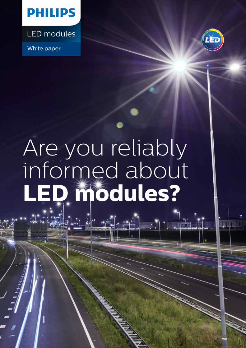
Are you reliably informed about LED modules? LED modules White paper
Transcript of Are you reliably informed about LED modules? - Philips · Light-emitting diode 3. Correlated color...
Are you reliably informed about LED modules?
LED modules
White paper
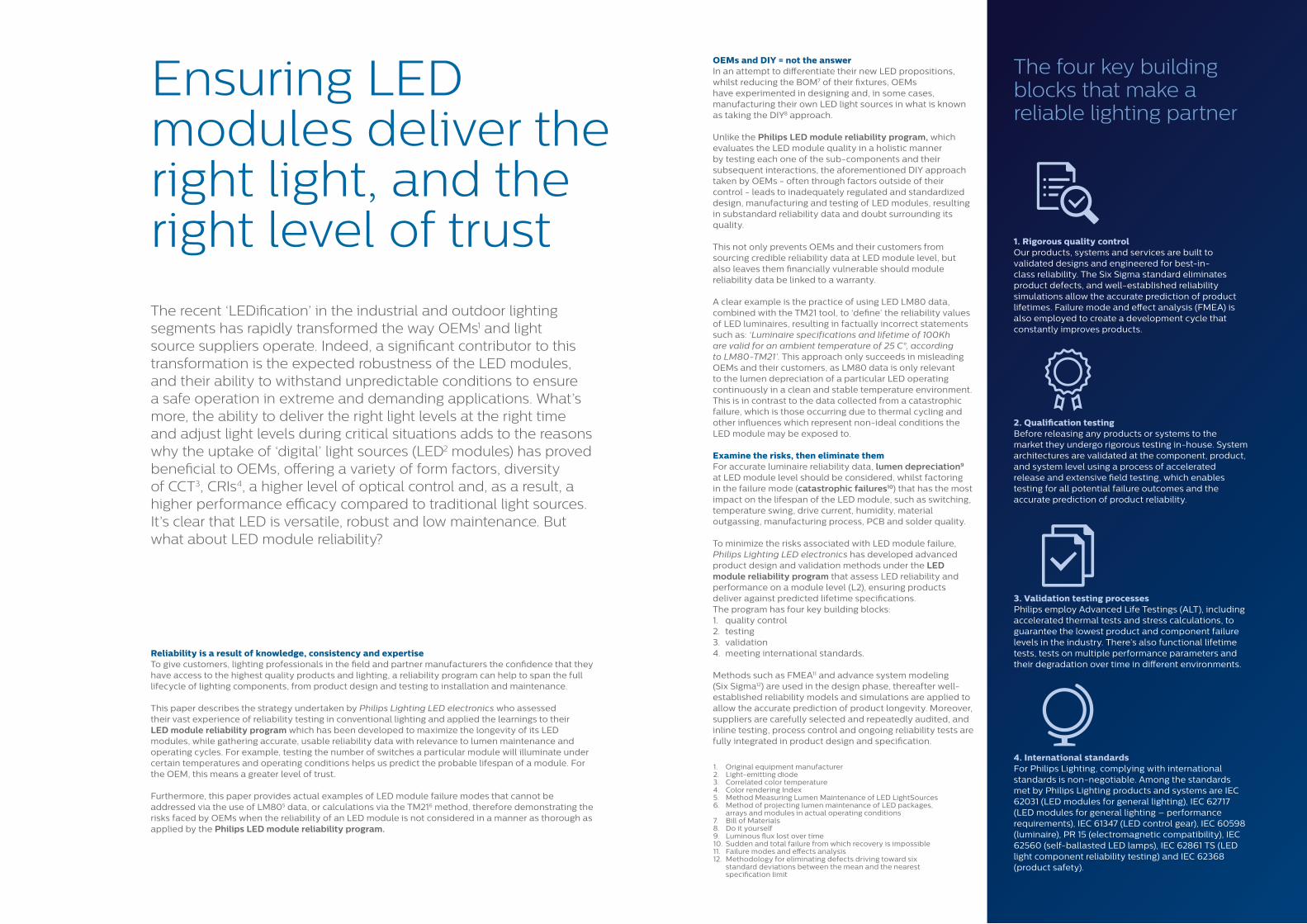
Ensuring LED modules deliver the right light, and the right level of trust
The recent ‘LEDification’ in the industrial and outdoor lighting segments has rapidly transformed the way OEMs1 and light source suppliers operate. Indeed, a significant contributor to this transformation is the expected robustness of the LED modules, and their ability to withstand unpredictable conditions to ensure a safe operation in extreme and demanding applications. What’s more, the ability to deliver the right light levels at the right time and adjust light levels during critical situations adds to the reasons why the uptake of ‘digital’ light sources (LED2 modules) has proved beneficial to OEMs, offering a variety of form factors, diversity of CCT3, CRIs4, a higher level of optical control and, as a result, a higher performance efficacy compared to traditional light sources. It’s clear that LED is versatile, robust and low maintenance. But what about LED module reliability?
Reliability is a result of knowledge, consistency and expertiseTo give customers, lighting professionals in the field and partner manufacturers the confidence that they have access to the highest quality products and lighting, a reliability program can help to span the full lifecycle of lighting components, from product design and testing to installation and maintenance.
This paper describes the strategy undertaken by Philips Lighting LED electronics who assessed their vast experience of reliability testing in conventional lighting and applied the learnings to their LED module reliability program which has been developed to maximize the longevity of its LED modules, while gathering accurate, usable reliability data with relevance to lumen maintenance and operating cycles. For example, testing the number of switches a particular module will illuminate under certain temperatures and operating conditions helps us predict the probable lifespan of a module. For the OEM, this means a greater level of trust.
Furthermore, this paper provides actual examples of LED module failure modes that cannot be addressed via the use of LM805 data, or calculations via the TM216 method, therefore demonstrating the risks faced by OEMs when the reliability of an LED module is not considered in a manner as thorough as applied by the Philips LED module reliability program.
OEMs and DIY = not the answerIn an attempt to differentiate their new LED propositions, whilst reducing the BOM7 of their fixtures, OEMs have experimented in designing and, in some cases, manufacturing their own LED light sources in what is known as taking the DIY8 approach.
Unlike the Philips LED module reliability program, which evaluates the LED module quality in a holistic manner by testing each one of the sub-components and their subsequent interactions, the aforementioned DIY approach taken by OEMs - often through factors outside of their control - leads to inadequately regulated and standardized design, manufacturing and testing of LED modules, resulting in substandard reliability data and doubt surrounding its quality.
This not only prevents OEMs and their customers from sourcing credible reliability data at LED module level, but also leaves them financially vulnerable should module reliability data be linked to a warranty.
A clear example is the practice of using LED LM80 data, combined with the TM21 tool, to ‘define’ the reliability values of LED luminaires, resulting in factually incorrect statements such as: ‘Luminaire specifications and lifetime of 100Kh are valid for an ambient temperature of 25 C°, according to LM80-TM21’. This approach only succeeds in misleading OEMs and their customers, as LM80 data is only relevant to the lumen depreciation of a particular LED operating continuously in a clean and stable temperature environment. This is in contrast to the data collected from a catastrophic failure, which is those occurring due to thermal cycling and other influences which represent non-ideal conditions the LED module may be exposed to.
Examine the risks, then eliminate themFor accurate luminaire reliability data, lumen depreciation9 at LED module level should be considered, whilst factoring in the failure mode (catastrophic failures10) that has the most impact on the lifespan of the LED module, such as switching, temperature swing, drive current, humidity, material outgassing, manufacturing process, PCB and solder quality.
To minimize the risks associated with LED module failure, Philips Lighting LED electronics has developed advanced product design and validation methods under the LED module reliability program that assess LED reliability and performance on a module level (L2), ensuring products deliver against predicted lifetime specifications. The program has four key building blocks:1. quality control2. testing3. validation4. meeting international standards.
Methods such as FMEA11 and advance system modeling (Six Sigma12) are used in the design phase, thereafter well-established reliability models and simulations are applied to allow the accurate prediction of product longevity. Moreover, suppliers are carefully selected and repeatedly audited, and inline testing, process control and ongoing reliability tests are fully integrated in product design and specification.
1. Original equipment manufacturer2. Light-emitting diode3. Correlated color temperature4. Color rendering Index5. Method Measuring Lumen Maintenance of LED LightSources6. Method of projecting lumen maintenance of LED packages,
arrays and modules in actual operating conditions7. Bill of Materials8. Do it yourself9. Luminous flux lost over time10. Sudden and total failure from which recovery is impossible11. Failure modes and effects analysis12. Methodology for eliminating defects driving toward six
standard deviations between the mean and the nearest specification limit
The four key building blocks that make a reliable lighting partner
1. Rigorous quality controlOur products, systems and services are built to validated designs and engineered for best-in-class reliability. The Six Sigma standard eliminates product defects, and well-established reliability simulations allow the accurate prediction of product lifetimes. Failure mode and effect analysis (FMEA) is also employed to create a development cycle that constantly improves products.
2. Qualification testingBefore releasing any products or systems to the market they undergo rigorous testing in-house. System architectures are validated at the component, product, and system level using a process of accelerated release and extensive field testing, which enables testing for all potential failure outcomes and the accurate prediction of product reliability.
3. Validation testing processesPhilips employ Advanced Life Testings (ALT), including accelerated thermal tests and stress calculations, to guarantee the lowest product and component failure levels in the industry. There’s also functional lifetime tests, tests on multiple performance parameters and their degradation over time in different environments.
4. International standardsFor Philips Lighting, complying with international standards is non-negotiable. Among the standards met by Philips Lighting products and systems are IEC 62031 (LED modules for general lighting), IEC 62717 (LED modules for general lighting – performance requirements), IEC 61347 (LED control gear), IEC 60598 (luminaire), PR 15 (electromagnetic compatibility), IEC 62560 (self-ballasted LED lamps), IEC 62861 TS (LED light component reliability testing) and IEC 62368 (product safety).
% f
ailu
res
ba
sed
on
lig
ht
up
te
stin
g
Cycles
0%0 500
FFgen3 LuxT Innelot
1000 1500 2000 2500 3000
2%
4%
6%
8%
10%
12%
14%
16%
18%
20%
FFgen3 LuxT SenjuFFgen2 Senju
FFgen2 InnelotFFgen1: Innelot/Lux R/Opt
0
0.002
0.004
0.006
0.008
0.01
0.012
0.014
0.016
0 2000 4000 6000 8000 10000 12000 14000
LM80 1000mA 105degree 3000K compared with FFg3 test 1000mA 110degree 4000K
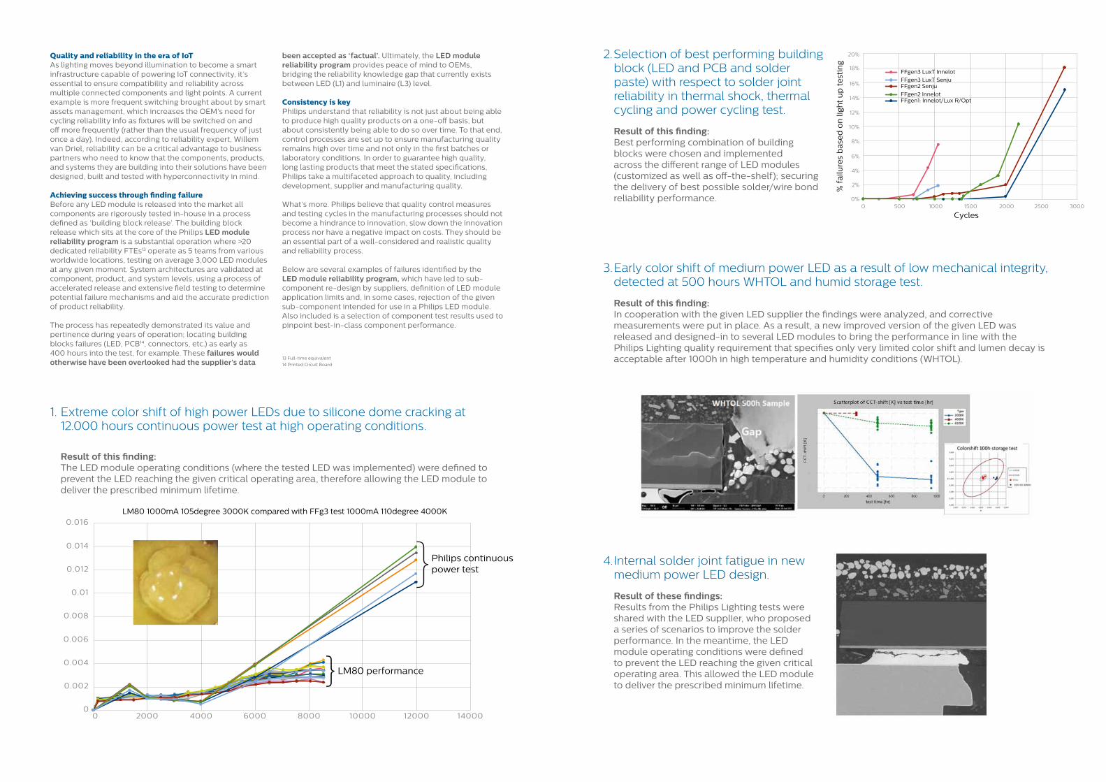
1. Extreme color shift of high power LEDs due to silicone dome cracking at 12.000 hours continuous power test at high operating conditions.
Result of this finding: The LED module operating conditions (where the tested LED was implemented) were defined to
prevent the LED reaching the given critical operating area, therefore allowing the LED module to deliver the prescribed minimum lifetime.
2. Selection of best performing building block (LED and PCB and solder paste) with respect to solder joint reliability in thermal shock, thermal cycling and power cycling test.
Result of this finding: Best performing combination of building
blocks were chosen and implemented across the different range of LED modules (customized as well as off-the-shelf); securing the delivery of best possible solder/wire bond reliability performance.
Quality and reliability in the era of IoTAs lighting moves beyond illumination to become a smart infrastructure capable of powering IoT connectivity, it’s essential to ensure compatibility and reliability across multiple connected components and light points. A current example is more frequent switching brought about by smart assets management, which increases the OEM’s need for cycling reliability info as fixtures will be switched on and off more frequently (rather than the usual frequency of just once a day). Indeed, according to reliability expert, Willem van Driel, reliability can be a critical advantage to business partners who need to know that the components, products, and systems they are building into their solutions have been designed, built and tested with hyperconnectivity in mind.
Achieving success through finding failureBefore any LED module is released into the market all components are rigorously tested in-house in a process defined as ‘building block release’. The building block release which sits at the core of the Philips LED module reliability program is a substantial operation where >20 dedicated reliability FTEs13 operate as 5 teams from various worldwide locations, testing on average 3,000 LED modules at any given moment. System architectures are validated at component, product, and system levels, using a process of accelerated release and extensive field testing to determine potential failure mechanisms and aid the accurate prediction of product reliability.
The process has repeatedly demonstrated its value and pertinence during years of operation; locating building blocks failures (LED, PCB14, connectors, etc.) as early as 400 hours into the test, for example. These failures would otherwise have been overlooked had the supplier’s data
been accepted as ‘factual’. Ultimately, the LED module reliability program provides peace of mind to OEMs, bridging the reliability knowledge gap that currently exists between LED (L1) and luminaire (L3) level.
Consistency is keyPhilips understand that reliability is not just about being able to produce high quality products on a one-off basis, but about consistently being able to do so over time. To that end, control processes are set up to ensure manufacturing quality remains high over time and not only in the first batches or laboratory conditions. In order to guarantee high quality, long lasting products that meet the stated specifications, Philips take a multifaceted approach to quality, including development, supplier and manufacturing quality.
What’s more. Philips believe that quality control measures and testing cycles in the manufacturing processes should not become a hindrance to innovation, slow down the innovation process nor have a negative impact on costs. They should be an essential part of a well-considered and realistic quality and reliability process.
Below are several examples of failures identified by the LED module reliability program, which have led to sub-component re-design by suppliers, definition of LED module application limits and, in some cases, rejection of the given sub-component intended for use in a Philips LED module.Also included is a selection of component test results used to pinpoint best-in-class component performance.
13 Full-time equivalent
14 Printed Circuit Board
3. Early color shift of medium power LED as a result of low mechanical integrity, detected at 500 hours WHTOL and humid storage test.
Result of this finding: In cooperation with the given LED supplier the findings were analyzed, and corrective
measurements were put in place. As a result, a new improved version of the given LED was released and designed-in to several LED modules to bring the performance in line with the Philips Lighting quality requirement that specifies only very limited color shift and lumen decay is acceptable after 1000h in high temperature and humidity conditions (WHTOL).
4. Internal solder joint fatigue in new medium power LED design.
Result of these findings: Results from the Philips Lighting tests were
shared with the LED supplier, who proposed a series of scenarios to improve the solder performance. In the meantime, the LED module operating conditions were defined to prevent the LED reaching the given critical operating area. This allowed the LED module to deliver the prescribed minimum lifetime.
Philips continuous power test
LM80 performance
}
}
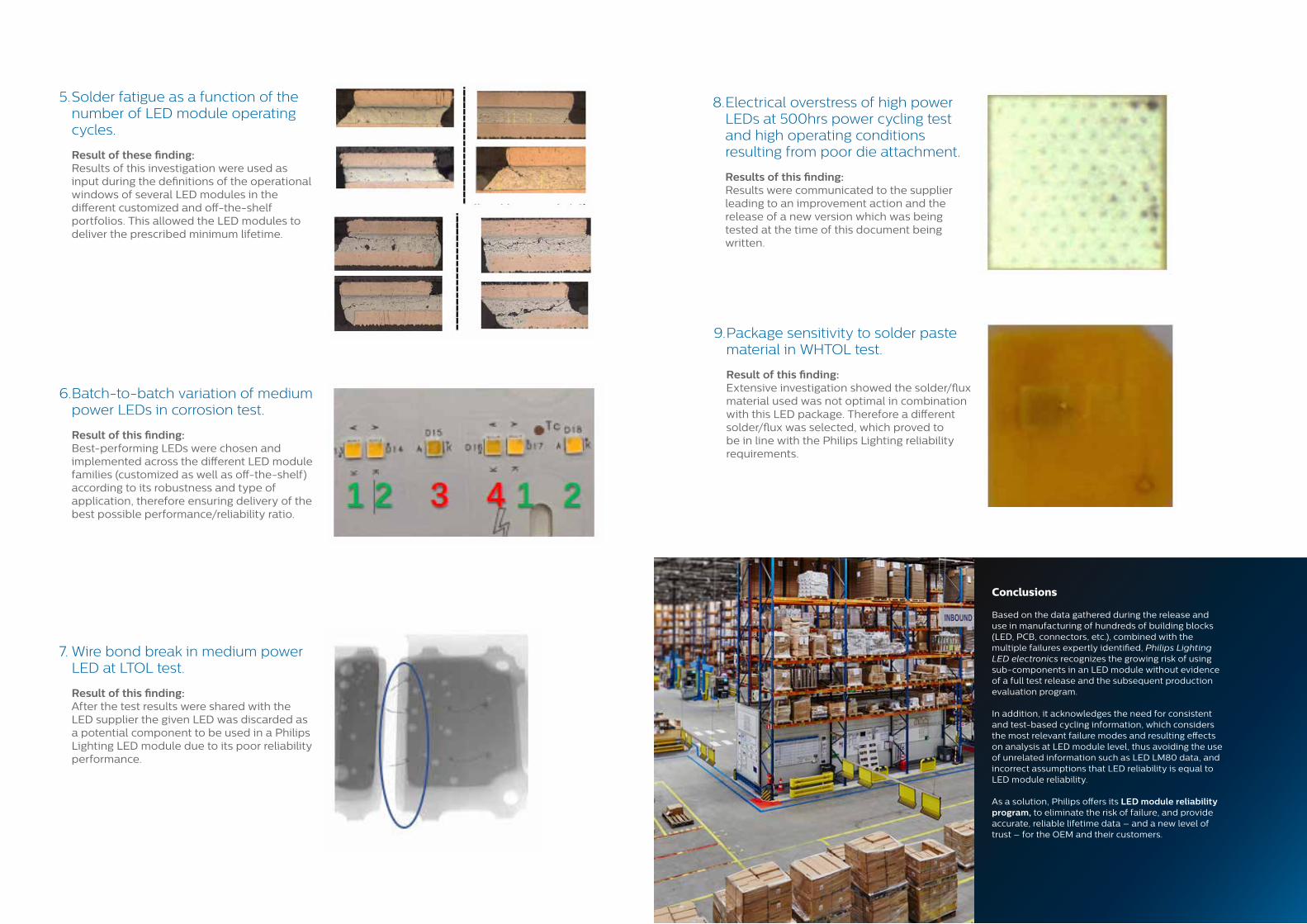
5. Solder fatigue as a function of the number of LED module operating cycles.
Result of these finding: Results of this investigation were used as
input during the definitions of the operational windows of several LED modules in the different customized and off-the-shelf portfolios. This allowed the LED modules to deliver the prescribed minimum lifetime.
6. Batch-to-batch variation of medium power LEDs in corrosion test.
Result of this finding: Best-performing LEDs were chosen and
implemented across the different LED module families (customized as well as off-the-shelf) according to its robustness and type of application, therefore ensuring delivery of the best possible performance/reliability ratio.
7. Wire bond break in medium power LED at LTOL test.
Result of this finding: After the test results were shared with the
LED supplier the given LED was discarded as a potential component to be used in a Philips Lighting LED module due to its poor reliability performance.
8. Electrical overstress of high power LEDs at 500hrs power cycling test and high operating conditions resulting from poor die attachment.
Results of this finding: Results were communicated to the supplier
leading to an improvement action and the release of a new version which was being tested at the time of this document being written.
9. Package sensitivity to solder paste material in WHTOL test.
Result of this finding: Extensive investigation showed the solder/flux
material used was not optimal in combination with this LED package. Therefore a different solder/flux was selected, which proved to be in line with the Philips Lighting reliability requirements.
Conclusions
Based on the data gathered during the release and use in manufacturing of hundreds of building blocks (LED, PCB, connectors, etc.), combined with the multiple failures expertly identified, Philips Lighting LED electronics recognizes the growing risk of using sub-components in an LED module without evidence of a full test release and the subsequent production evaluation program.
In addition, it acknowledges the need for consistent and test-based cycling information, which considers the most relevant failure modes and resulting effects on analysis at LED module level, thus avoiding the use of unrelated information such as LED LM80 data, and incorrect assumptions that LED reliability is equal to LED module reliability.
As a solution, Philips offers its LED module reliability program, to eliminate the risk of failure, and provide accurate, reliable lifetime data – and a new level of trust – for the OEM and their customers.
©2019 Signify Holding. All rights reserved. The information provided herein is subject to change, without notice. Signify does not give any representation or warranty as to the accuracy or completeness of the information included herein and shall not be liable for any action in reliance thereon. The information presented in this document is not intended as any commercial offer and does not form part of any quotation or contract, unless otherwise agreed by Signify.Philips and the Philips Shield Emblem are registered trademarks of Koninklijke Philips N.V. All other trademarks are owned by Signify Holding or their respective owners. www.philips.com/technology