ArduinoEngineerinArduino Engineerinng Basicsng Basics ...
18
In This Part Chapter 1: Getting Up and Blinking with the Arduino Chapter 2: Digital Inputs, Outputs, and Pulse-Width M Modulation Chapter 3: Reading Analog Sensors Part I I I Arduino Engineerin ng Basics Arduino Engineerin ng Basics COPYRIGHTED MATERIAL
Transcript of ArduinoEngineerinArduino Engineerinng Basicsng Basics ...
In This Part
Chapter 1: Getting Up and Blinking with the Arduino
Chapter 2: Digital Inputs, Outputs, and Pulse-Width MModulation
Chapter 3: Reading Analog Sensors
P a r t
II I Arduino Engineerinng Basics Arduino Engineerinng BasicsCO
PYRIGHTED
MATERIA
L


3
Parts You’ll Need for This Chapter:
Arduino Uno
USB cable
CODE AND DIGITAL CONTENT FOR THIS CHAPTER
Code downloads, videos, and other digital content for this chapter can be
found at www.exploringarduino.com/content/ch1 .
In addition, all code can be found at www.wiley.com/go/exploringarduino on
the Download Code tab. The code is in the chapter 01 download and individu-
ally named according to the names throughout the chapter.
Now that you have some perspective on the Arduino platform and its ca-
pabilities, it’s time to explore your options in the world of Arduino. In this
chapter, you examine the available hardware, learn about the programming
environment and language, and get your fi rst program up and running.
Once you have a grip on the functionality that the Arduino can provide,
you’ll write your fi rst program and get the Arduino to blink!
C H A P T E R
1 Getting Up and Blinking
with the Arduinoe Arduino

4 Part I ■ Arduino Engineering Basics
NOTE To follow along with a video that introduces the Arduino platform, visitwww.jeremyblum.com/2011/01/02/arduino-tutorial-series-it-begins/./You can also find this video on the Wiley website shown at the beginning of thischapter.
Exploring the Arduino Ecosystem
In your adventures with the Arduino, you’ll depend on three main components
for your projects:
■ The Arduino board itself
■ External hardware (including both shields and hand-made circuits, which
you’ll explore throughout this book)
■ The Arduino integrated development environment, or Arduino IDE
All these system components work in tandem to enable you do just about
anything with your Arduino.
You have a lot of options when it comes to Arduino development boards, but
this book focuses on using offi cial Arduino boards. Because the boards are all
designed to be programmable via the same IDE, you can generally use any of
the modern Arduino boards to complete the projects in this book with zero or
minor changes. However, when necessary, you’ll see caveats about using different
boards for various projects. The majority of the projects use the Arduino Uno.
You start by exploring the basic functionality baked in to every Arduino board.
Then you examine the differences between each modern board so that you can
make an informed decision when choosing a board to use for your next project.
Arduino Functionality All Arduino boards have a few key capabilities and functions. Take a moment
to examine the Arduino Uno (see Figure 1-1); it will be your base confi guration.
These are some key components that you’ll be concerning yourself with:
■ Atmel microcontroller
■ USB programming/communication interface(s)
■ Voltage regulator and power connections
■ Breakout I/O pins
■ Debug, Power, and RX/TX LEDs
■ Reset button
■ In-circuit serial programmer (ICSP) connector(s)

USB
con
nect
or
Res
et b
utto
n
7–12
VDC
inpu
t
Seri
al-t
o-U
SB c
ircu
itry
Gene
ral I
/O
Pow
er a
nd a
uxili
ary
pins
MCU
pro
gram
min
g co
nnec
tor (
ICSP
)
Deb
ug L
ED
Anal
og-t
o-di
gita
l con
vert
er (A
DC)
inpu
ts
ATM
ega
328
MC
U
Figu
re 1
-1: A
rdui
no U
no c
ompo
nent
s C
redi
t: A
rdui
no,www.arduino.cc
6 Part I ■ Arduino Engineering Basics
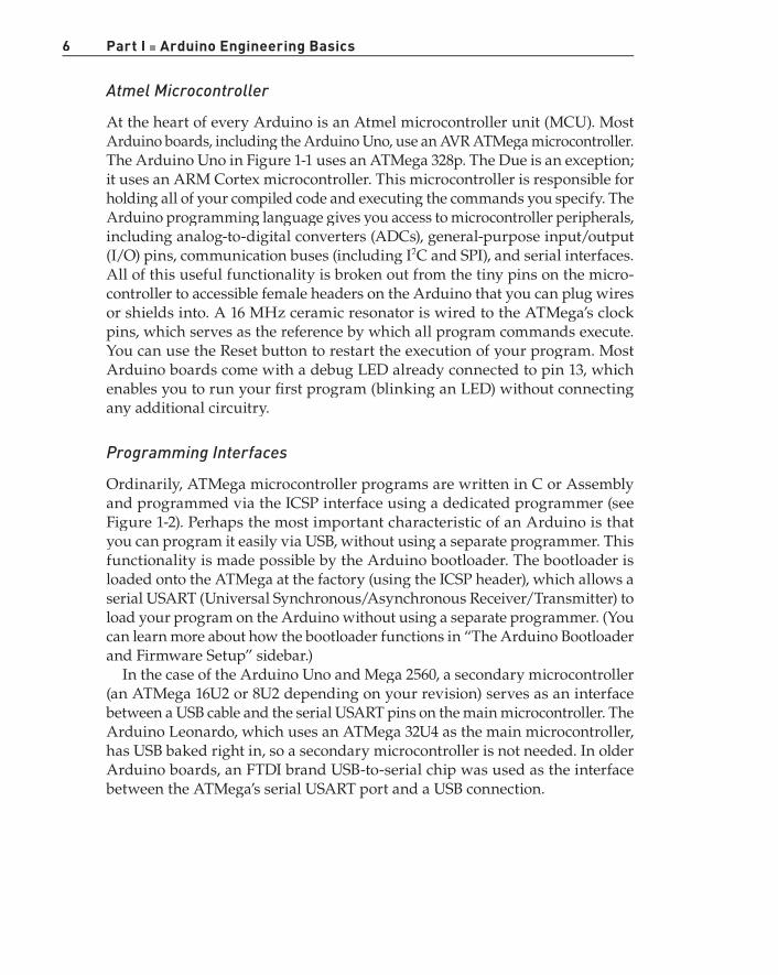
Atmel Microcontroller
At the heart of every Arduino is an Atmel microcontroller unit (MCU). Most
Arduino boards, including the Arduino Uno, use an AVR ATMega microcontroller.
The Arduino Uno in Figure 1-1 uses an ATMega 328p. The Due is an exception;
it uses an ARM Cortex microcontroller. This microcontroller is responsible for
holding all of your compiled code and executing the commands you specify. The
Arduino programming language gives you access to microcontroller peripherals,
including analog-to-digital converters (ADCs), general-purpose input/output
(I/O) pins, communication buses (including I2C and SPI), and serial interfaces.
All of this useful functionality is broken out from the tiny pins on the micro-
controller to accessible female headers on the Arduino that you can plug wires
or shields into. A 16 MHz ceramic resonator is wired to the ATMega’s clock
pins, which serves as the reference by which all program commands execute.
You can use the Reset button to restart the execution of your program. Most
Arduino boards come with a debug LED already connected to pin 13, which
enables you to run your fi rst program (blinking an LED) without connecting
any additional circuitry.
Programming Interfaces
Ordinarily, ATMega microcontroller programs are written in C or Assembly
and programmed via the ICSP interface using a dedicated programmer (see
Figure 1-2). Perhaps the most important characteristic of an Arduino is that
you can program it easily via USB, without using a separate programmer. This
functionality is made possible by the Arduino bootloader. The bootloader is
loaded onto the ATMega at the factory (using the ICSP header), which allows a
serial USART (Universal Synchronous/Asynchronous Receiver/Transmitter) to
load your program on the Arduino without using a separate programmer. (You
can learn more about how the bootloader functions in “The Arduino Bootloader
and Firmware Setup” sidebar.)
In the case of the Arduino Uno and Mega 2560, a secondary microcontroller
(an ATMega 16U2 or 8U2 depending on your revision) serves as an interface
between a USB cable and the serial USART pins on the main microcontroller. The
Arduino Leonardo, which uses an ATMega 32U4 as the main microcontroller,
has USB baked right in, so a secondary microcontroller is not needed. In older
Arduino boards, an FTDI brand USB-to-serial chip was used as the interface
between the ATMega’s serial USART port and a USB connection.

Chapter 1 ■ Getting Up and Blinking with the Arduino 7
Figure 1-2: AVR ISP MKII programmer
General I/O and ADCs
The part of the Arduino that you’ll care the most about during your projects is
the general-purpose I/O and ADC pins. All of these pins can be individually
addressed via the programs you’ll write. All of them can serve as digital inputs
and outputs. The ADC pins can also act as analog inputs that can measure volt-
ages between 0 and 5V (usually from resistive sensors). Many of these pins are
also multiplexed to serve additional functions, which you will explore during
your projects. These special functions include various communication interfaces,
serial interfaces, pulse-width-modulated outputs, and external interrupts.
Power Supplies
For the majority of your projects, you will simply use the 5V power that is
provided over your USB cable. However, when you’re ready to untether your
project from a computer, you have other power options. The Arduino can accept
between 6V and 20V (7-12V recommend) via the direct current (DC) barrel jack
connector, or into the Vin
pin. The Arduino has built-in 5V and 3.3V regulators:
■ 5V is used for all the logic on the board. In other words, when you toggle
a digital I/O pin, you are toggling it between 5V and 0V.
■ 3.3V is broken out to a pin to accommodate 3.3V shields and external
circuitry.
Cre
dit:
© 2
013
Atm
el C
orpo
ratio
n.A
ll r i
ghts
res
erve
d.
8 Part I ■ Arduino Engineering Basics
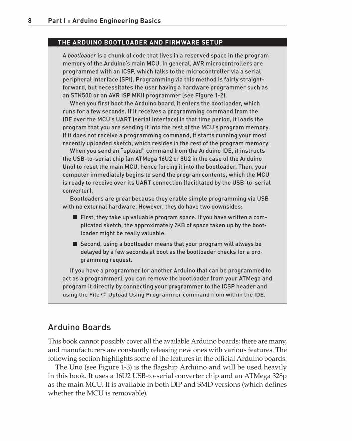
THE ARDUINO BOOTLOADER AND FIRMWARE SETUP
A bootloader is a chunk of code that lives in a reserved space in the program rmemory of the Arduino’s main MCU. In general, AVR microcontrollers are programmed with an ICSP, which talks to the microcontroller via a serial peripheral interface (SPI). Programming via this method is fairly straight-forward, but necessitates the user having a hardware programmer such as an STK500 or an AVR ISP MKII programmer (see Figure 1-2).
When you first boot the Arduino board, it enters the bootloader, whichruns for a few seconds. If it receives a programming command from the IDE over the MCU’s UART (serial interface) in that time period, it loads the program that you are sending it into the rest of the MCU’s program memory. If it does not receive a programming command, it starts running your most recently uploaded sketch, which resides in the rest of the program memory.
When you send an “upload” command from the Arduino IDE, it instructsthe USB-to-serial chip (an ATMega 16U2 or 8U2 in the case of the Arduino Uno) to reset the main MCU, hence forcing it into the bootloader. Then, yourcomputer immediately begins to send the program contents, which the MCU is ready to receive over its UART connection (facilitated by the USB-to-serial converter).
Bootloaders are great because they enable simple programming via USB with no external hardware. However, they do have two downsides:
■ First, they take up valuable program space. If you have written a com-plicated sketch, the approximately 2KB of space taken up by the boot-loader might be really valuable.
■ Second, using a bootloader means that your program will always bedelayed by a few seconds at boot as the bootloader checks for a pro-gramming request.
If you have a programmer (or another Arduino that can be programmed toact as a programmer), you can remove the bootloader from your ATMega and program it directly by connecting your programmer to the ICSP header and using the File ➪ Upload Using Programmer command from within the IDE.
Arduino Boards This book cannot possibly cover all the available Arduino boards; there are many,
and manufacturers are constantly releasing new ones with various features. The
following section highlights some of the features in the offi cial Arduino boards.
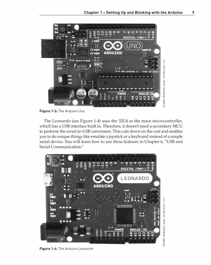
The Uno (see Figure 1-3) is the fl agship Arduino and will be used heavily
in this book. It uses a 16U2 USB-to-serial converter chip and an ATMega 328p
as the main MCU. It is available in both DIP and SMD versions (which defi nes
whether the MCU is removable).
Chapter 1 ■ Getting Up and Blinking with the Arduino 9
Figure 1-3: The Arduino Uno
The Leonardo (see Figure 1-4) uses the 32U4 as the main microcontroller,
which has a USB interface built in. Therefore, it doesn’t need a secondary MCU
to perform the serial-to-USB conversion. This cuts down on the cost and enables
you to do unique things like emulate a joystick or a keyboard instead of a simple
serial device. You will learn how to use these features in Chapter 6, “USB and
Serial Communication.”
Figure 1-4: The Arduino Leonardo
Cre
dit:
Ard
uino
,www.arduino.cc
Cre
dit:
Ard
uino
,www.arduino.cc
10 Part I ■ Arduino Engineering Basics
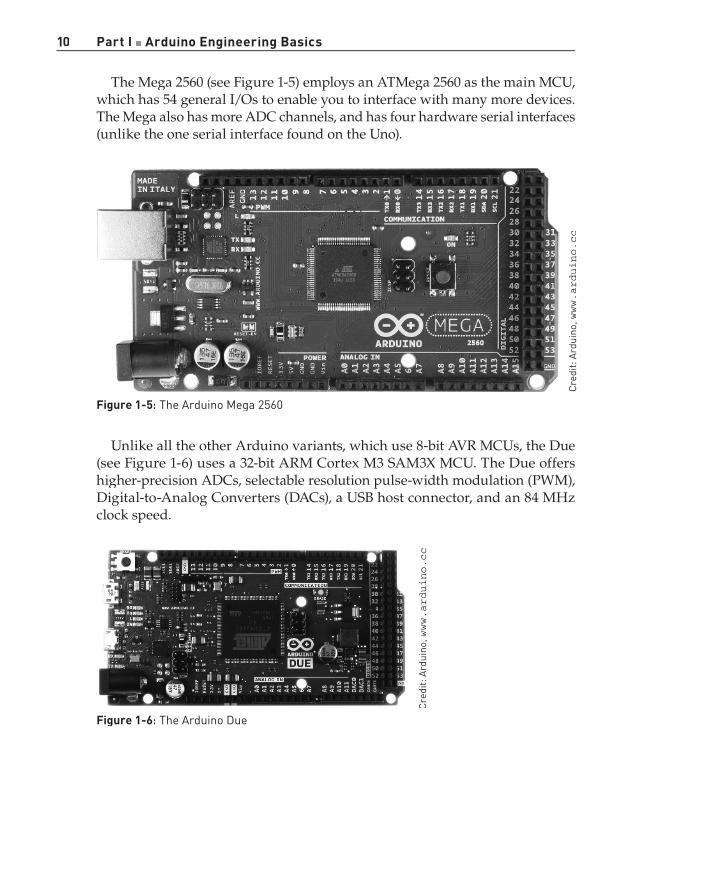
The Mega 2560 (see Figure 1-5) employs an ATMega 2560 as the main MCU,
which has 54 general I/Os to enable you to interface with many more devices.
The Mega also has more ADC channels, and has four hardware serial interfaces
(unlike the one serial interface found on the Uno).
Figure 1-5: The Arduino Mega 2560
Unlike all the other Arduino variants, which use 8-bit AVR MCUs, the Due
(see Figure 1-6) uses a 32-bit ARM Cortex M3 SAM3X MCU. The Due offers
higher-precision ADCs, selectable resolution pulse-width modulation (PWM),
Digital-to-Analog Converters (DACs), a USB host connector, and an 84 MHz
clock speed.
Figure 1-6: The Arduino Due
Cre
dit:
Ard
uino
,www.arduino.cc
Cre
dit:
Ard
uino
,www.arduino.cc

Chapter 1 ■ Getting Up and Blinking with the Arduino 11
The Nano (see Figure 1-7) is designed to be mounted right into a breadboard
socket. Its small form factor makes it perfect for use in more fi nished projects.
Figure 1-7: The Arduino Nano
The Mega ADK (see Figure 1-8) is very similar to the Mega 2560, except that
it has USB host functionality, allowing it to connect to an Android phone so
that it can communicate with apps that you write.
Figure 1-8: The Arduino Mega ADK
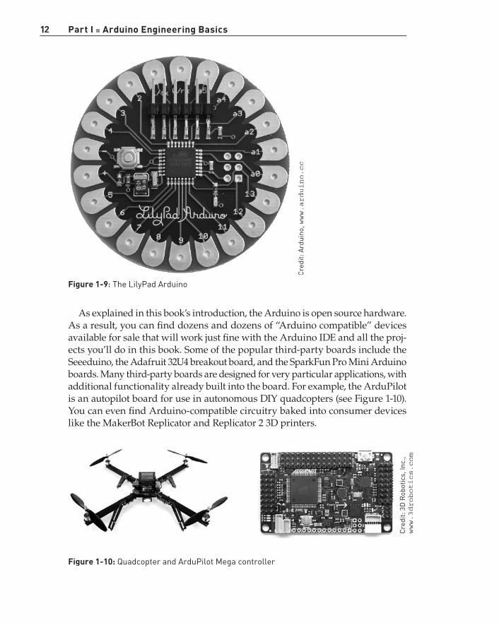
The LilyPad (see Figure 1-9) is unique because it is designed to be sewn into
clothing. Using conductive thread, you can wire it up to sewable sensors, LEDs,
and more. To keep size down, you need to program it using an FTDI cable.
Cre
dit:
Ard
uino
,www.arduino.cc
Cre
dit:
Coo
king
Hac
ks,
www.cookinghacks.com
12 Part I ■ Arduino Engineering Basics
Figure 1-9: The LilyPad Arduino
As explained in this book’s introduction, the Arduino is open source hardware.
As a result, you can fi nd dozens and dozens of “Arduino compatible” devices
available for sale that will work just fi ne with the Arduino IDE and all the proj-
ects you’ll do in this book. Some of the popular third-party boards include the
Seeeduino, the Adafruit 32U4 breakout board, and the SparkFun Pro Mini Arduino
boards. Many third-party boards are designed for very particular applications, with
additional functionality already built into the board. For example, the ArduPilot
is an autopilot board for use in autonomous DIY quadcopters (see Figure 1-10).
You can even fi nd Arduino-compatible circuitry baked into consumer devices
like the MakerBot Replicator and Replicator 2 3D printers.
Figure 1-10: Quadcopter and ArduPilot Mega controller
Cre
dit:
Ard
uino
,www.arduino.cc
Cre
dit:
3D
Rob
otic
s, In
c.,
www.3drobotics.com
Chapter 1 ■ Getting Up and Blinking with the Arduino 13
Creating Your First Program
Now that you understand the hardware that you’ll be using throughout this
book, you can install the software and run your fi rst program. Start by down-
loading the Arduino software to your computer.
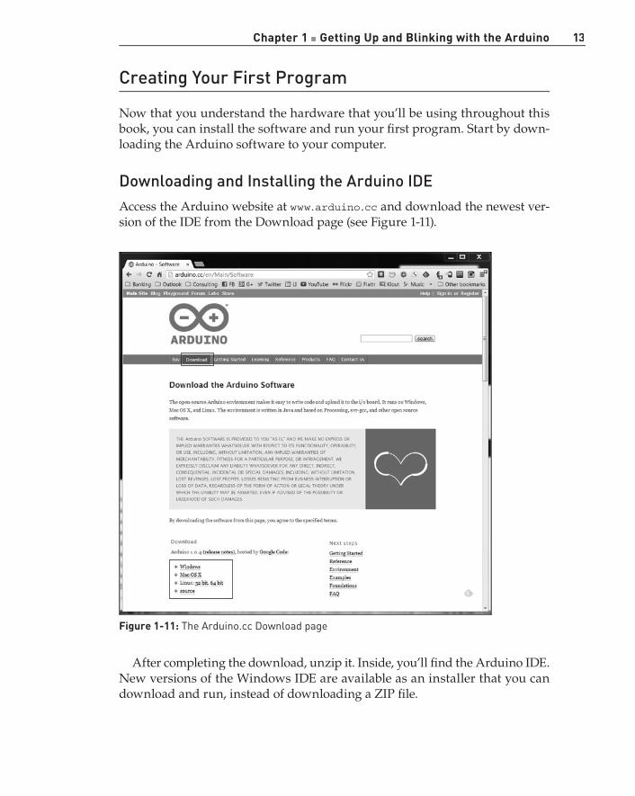
Downloading and Installing the Arduino IDE Access the Arduino website at www.arduino.cc and download the newest ver-
sion of the IDE from the Download page (see Figure 1-11).
Figure 1-11: The Arduino.cc Download page
After completing the download, unzip it. Inside, you’ll fi nd the Arduino IDE.
New versions of the Windows IDE are available as an installer that you can
download and run, instead of downloading a ZIP fi le.

14 Part I4 ■ Arduino Engineering Basics
Running the IDE and Connecting to the Arduino Now that you have the IDE downloaded and ready to run, you can connect the
Arduino to your computer via USB, as shown in Figure 1-12. Mac and Linux
machines install the drivers (mostly) automatically.
If you are using OS X, the fi rst time you plug in an Uno or a Mega 2560, you
will get a notifi cation that a new network device has been added. Click the
Network Preferences button. In the new window, click Apply. Even though the
board will appear as “Not Confi gured” in the network device list, it will be
ready to use. Now, quit System Preferences.
If you are using a modern Arduino on a Windows computer, you will prob-
ably need to install drivers. You can skip the following directions if you are not
using a Windows computer that needs to have drivers installed. If you installed
the IDE using the Windows installer, then these steps have been completed for
you. If you downloaded the ZIP on your Windows machine, then you will need
to follow the directions shown next.
Figure 1-12: Arduino Uno connected to a computer via USB

Chapter 1 ■ Getting Up and Blinking with the Arduino 15
On your Windows computer, follow these steps to install the drivers (instruc-
tions adapted from the Arduino.cc website):
1. Wait for the automatic install process to fail.
2. Open the Start menu, right-click My Computer, and select Properties.
3. Choose Device Manager.
4. Look under Ports (COM and LPT) for the Arduino that you connected.
5. Right-click it and choose Update Driver Software.
6. Choose to browse your computer for software.
7. Select the appropriate driver from the drivers directory of the Arduino
IDE that you just downloaded (not the FTDI drivers directory).
8. Windows will now fi nish the driver installation.
Now, launch the Arduino IDE. You’re ready to load your fi rst program onto
your Arduino. To ensure that everything is working as expected, you’ll load the
Blink example program, which will blink the onboard LED. Most Arduinos have
an LED connected to pin 13. Navigate to File ➪ Examples ➪ Basic, and click the
Blink program. This opens a new IDE window with the Blink program already
written for you. First, you’ll program the Arduino with this example sketch,
and then you’ll analyze the program to understand the important components
so that you can start to write your own programs in the next chapter.
Before you load the program, you need to tell the IDE what kind of Arduino
you have connected and what port it is connected to. Go to Tools ➪ Board and
ensure that the right board is selected. This example uses the Uno, but if you
are using a different board, select that one (assuming that it also has an LED
connected to pin 13).
The last step before programming is to tell the IDE what port your board is
connected to. Navigate to Tools ➪ Serial Port and select the appropriate port.
On Windows machines, this will be COM* , where * is some number representing
the serial port number.
TIP If you have multiple serial devices attached to your computer, try unpluggingyour board to see which COM port disappears from the menu; then plug it back inand select that COM port.
On Linux and Mac computers, the serial port looks something like /dev/tty
.usbmodem* or /dev/tty.usbserial* , where * is a string of alphanumeric
characters.
16 Part I ■ Arduino Engineering Basics
You’re fi nally ready to load your fi rst program. Click the Upload button ( ) on
the top left of the IDE. The status bar at the bottom of the IDE shows a progress
bar as it compiles and uploads your program. When the upload completes, the
yellow LED on your Arduino should be blinking once per second. Congratulations!
You’ve just uploaded your fi rst Arduino program.
Breaking Down Your First Program Take a moment to deconstruct the Blink program so that you understand the
basic structure of programs written for the Arduino. Consider Figure 1-13. The
numbered callouts shown in the fi gure correspond to the following list.
Here’s how the code works, piece by piece:
1. This is a multiline comment. Comments are important for documenting
your code. Everything you write between these symbols will not be com-
piled or even seen by your Arduino. Multiline comments start with /*
and end with */ . Multiline comments are generally used when you have
to say a lot (like the description of this program).
2. This is a single-line comment. When you put // on any line, the compiler
ignores all text after that symbol on the same line. This is great for anno-
tating specifi c lines of code or for “commenting out” a particular line of
code that you believe might be causing problems.
3. This code is a variable declaration. A variable is a place in the Arduino’s
memory that holds information. Variables have different types. In this
case, it’s of type int , which means it will hold an integer. In this case, an
integer variable called led is being set to the value of 13 , the pin that the
LED is connected to on the Arduino Uno. Throughout the rest of the pro-
gram, we can simply use led whenever we want to control pin 13. Setting
variables is useful because you can just change this one line if you hook
up your LED to a different I/O pin later on; the rest of the code will still
work as expected.
4. void setup() is one of two functions that must be included in every
Arduino program. A function is a piece of code that does a specifi c task.
Code within the curly braces of the setup() function is executed once at
the start of the program. This is useful for one-time settings, such as setting
the direction of pins, initializing communication interfaces, and so on.

Chapter 1 ■ Getting Up and Blinking with the Arduino 17
1
2
3
4
5
6789
10
Figure 1-13: The components of the Blink program
5. The Arduino’s digital pins can function as input or outputs. To confi gure
their direction, use the command pinMode() . This command takes two
arguments. An argument gives commands information on how they should
operate. Arguments are placed inside the parentheses following a com-
mand. The fi rst argument to pinMode determines which pin is having its
direction set. Because you defi ned the led variable earlier in the program,
you are telling the command that you want to set the direction of pin 13.
The second argument sets the direction of the pin: INPUT or OUTPUT . Pins
are inputs by default, so you need to explicitly set them to outputs if you
want them to function as outputs. Because you want to light an LED, you
have set the led pin to an output (current is fl owing out of the I/O pin).
Note that you have to do this only one time. It will then function as an
output for the rest of the program, or until you change it to an input.

18 Part I8 ■ Arduino Engineering Basics
6. The second required function in all Arduino programs is void loop() .
The contents of the loop function repeat forever as long as the Arduino
is on. If you want your Arduino to do something once at boot only, you
still need to include the loop function, but you can leave it empty.
7. digitalWrite() is used to set the state of an output pin. It can set the pin
to either 5V or 0V. When an LED and resistor is connected to a pin, set-
ting it to 5V will enable you to light up the LED. (You learn more about
this in the next chapter.) The fi rst argument to digitalWrite() is the pin
you want to control. The second argument is the value you want to set
it to, either HIGH (5V) or LOW (0V). The pin remains in this state until it is
changed in the code.
8. The delay() function accepts one argument: a delay time in milliseconds.
When calling delay() , the Arduino stops doing anything for the amount
of time specifi ed. In this case, you are delaying the program for 1000ms,
or 1 second. This results in the LED staying on for 1 second before you
execute the next command.
9. Here, digitalWrite() is used to turn the LED off, by setting the pin state
to LOW .
10. Again, we delay for 1 second to keep the LED in the off state before the
loop repeats and switches to the on state again.
That’s all there is to it. Don’t be intimidated if you don’t fully understand
all the code yet. As you put together more examples in the following chapters,
you’ll become more and more profi cient at understanding program fl ow, and
writing your own code.
Summary
In this chapter you learned about the following:
■ All the components that comprise an Arduino board
■ How the Arduino bootloader allows you to program Arduino fi rmware
over a USB connection
■ The differences between the various available Arduino boards
■ How to connect and install the Arduino with your system
■ How to load and run your fi rst program