Archives/ORNL... · – Cryogenic dielectric reduces size and increases current carrying capacity....
35
DOE Superconductivity Program for Electric Systems - 2000 Annual Peer Review A Superconductivity Partnership Initiative (SPI) Project 1 +LJK7HPSHUDWXUH +LJK7HPSHUDWXUH 6XSHUFRQGXFWLQJ 6XSHUFRQGXFWLQJ&DEOH &DEOH 2000 Annual Peer Review Superconductivity Program for Electric Systems U.S. Department of Energy July 17-19, 2000 Washington, DC 2 World’s First Industrial Field Test of HTS Cable Delivers Power To Industrial Customer
Transcript of Archives/ORNL... · – Cryogenic dielectric reduces size and increases current carrying capacity....

DOE Superconductivity Program for Electric Systems - 2000 Annual Peer Review
A Superconductivity Partnership Initiative (SPI) Project
1
����������� ������������ �� ����� ������ ����� �����������������
2000 Annual Peer Review
Superconductivity Programfor Electric SystemsU.S. Department of Energy
July 17-19, 2000Washington, DC
2
World’s First Industrial Field Test of HTS CableDelivers Power To Industrial Customer

DOE Superconductivity Program for Electric Systems - 2000 Annual Peer Review
A Superconductivity Partnership Initiative (SPI) Project
2
3
Presentation Outline
• Southwire Activities (David Lindsay, Southwire)– Introduction–30-m Cable Installation–30-m Cable Operation
• FY 2000 Results–30-m Cable Off-Line Testing (Mike Gouge, ORNL)–5-m Cable Research–Component Development–Cryogenic Dielectrics Research (John Stovall, ORNL)
• FY 2000 Performance / FY 2001 Plans• Technology Integration• Summary
4
Project Participants at Southwire and ORNL
• SouthwireJohn ArmstrongZack ButterworthHugh ButlerRandy DenmonDwain GosdinR. L. HugheyGary HyattDonnie KittleKim KnucklesDavid Lindsay
• Oak Ridge National LaboratoryGlenn BarberLarry BaylorBob BensonJonathan DemkoAlvin EllisPaul FisherChris FosterMike GougeRobert Hawsey
Steve OwensRon MartinSammy PollardDavid ReeceMark RodenUday SinhaJerry TolbertLewis WatersNick Ware
•Randy JamesWinston LuePatrick MartinMarshall PaceVaughn PataniaIsidor SauersBill SchwenterlyDennis SparksJohn Stovall

DOE Superconductivity Program for Electric Systems - 2000 Annual Peer Review
A Superconductivity Partnership Initiative (SPI) Project
3
5
Other Project Participants
• Argonne National Laboratory• EURUS - Plastronic• Georgia Transmission• IGC Superpower• Southern Cal Edison• Southern Company• Subcontractors and Consultants
6
• Operation of 30-meter three-phase cable in FY 2000 atSouthwire Headquarters in Carrollton, Georgia.
SPI Project Goal (February 1997)
First U.S. Industrial SPI Cable Installation
• At the end of the three year project, a high temperaturesuperconducting (HTS) cable will be providing electricservice to a large industrial customer at 12.4-kV and1.25-kA.

DOE Superconductivity Program for Electric Systems - 2000 Annual Peer Review
A Superconductivity Partnership Initiative (SPI) Project
4
7
Cable Cross Sectional View
• Features–Magnetic field shielded.–Both conductor and dielectric are wrapped from tapes.–Cryogenic dielectric reduces size and increases current carrying
capacity.–Flexible cable to allow reeling
8
Southwire Project Status
• FY 2000 goals have been completed.–Cables installed Aug 99–Cryogenic system delivered Sept. 99–Cable terminations assembled Sept. 99–Cryogenic system tested Oct. 99–Off-line electrical testing Nov/Dec 99–Cables energized Jan. 5, 2000–Dedication ceremony Feb. 18, 2000–Continuous operation started Feb. 21, 2000–Off-line research June 7- 30, 2000

DOE Superconductivity Program for Electric Systems - 2000 Annual Peer Review
A Superconductivity Partnership Initiative (SPI) Project
5
9
Under construction,as shown last year
In operation this year
HTS Cable Site Progress
10
Site ready forcable installation
Phase 3 set in place
Cables Installed - 8/24/99

DOE Superconductivity Program for Electric Systems - 2000 Annual Peer Review
A Superconductivity Partnership Initiative (SPI) Project
6
11
PHPK, Inc. As delivered
Installed and operational
Cryogenic System Delivered - 9/2/99
12
Assembly in progress
Assembly completed
Termination Assembly - 9/23/99

DOE Superconductivity Program for Electric Systems - 2000 Annual Peer Review
A Superconductivity Partnership Initiative (SPI) Project
7
13
System Testing Oct. - Dec. 1999
• Cryogenic system acceptanceand testing
• Off-line electrical testing ofsuperconducting cables
• Circuit breakers andprotection system
14
Phase 3 Phase 2 Phase 1
Electrical Control and Protection Panel for HTS Cables
Cables First Energized on January 5, 2000

DOE Superconductivity Program for Electric Systems - 2000 Annual Peer Review
A Superconductivity Partnership Initiative (SPI) Project
8
15
Computer (PLC) Controlled Cryogenic System
16
Georgia Governor and Energy Secretary
Dedication Ceremony - Feb. 18, 2000

DOE Superconductivity Program for Electric Systems - 2000 Annual Peer Review
A Superconductivity Partnership Initiative (SPI) Project
9
17
Electrical Block Diagram of SW HTS Cable
Substation
40 MVA
HTS Cable
Transmission
ThreeManufacturing
Plants
Distribution
CopperRodMill
Customer Loads
Existing Overhead Lines12.4 kV
Switching Configurations1. Overhead only2. HTS Cable only3. Both
115 kV
18
Switchyard is part of Integrated TransmissionSystem and provided by Georgia Power
Substation
• Two way transmissionfeed–one from Yates Power
Plant–one from Bremen
switchyard
• 40 MVA–Two 20 MVA matched
unit, non regulating,transformers
–115 kV high side / 12.4 kVlow side
• Two 12.4 kV feeders out

DOE Superconductivity Program for Electric Systems - 2000 Annual Peer Review
A Superconductivity Partnership Initiative (SPI) Project
10
19
Two 12.4 kV Feeders Exiting Substation
• Southwire feeder (left)– HTS cable on SW feeder
• Copper Division Southwire feeder(right)
• Both 1033.5 ACSR (aluminumconductor steel reinforced)
• 12.4 kV protection on Southwirefeeder is a vacuum breaker with a re-closing relay set for three shotbefore lock out.
• Symmetrical 3 phase fault current isaround 14,000 amps at 12.4 kV
20
May 2000 - HTS Phase 1 Current (1 hour data)
0
200
400
600
800
1000
1200
1400
4/30/2000 5/7/2000 5/14/2000 5/21/2000 5/28/2000
Cu
rren
t, a
mp
s rm
s
Phase 1 2 3Amps Amps Amps
Average 853 863 845Std Dev 119 116 118Min 219 244 218Max 1,084 1,088 1,073
Plant shutdown for maintenance
30 days of continuous operation
HTS Phase 1 Current for May 2000

DOE Superconductivity Program for Electric Systems - 2000 Annual Peer Review
A Superconductivity Partnership Initiative (SPI) Project
11
21
74
75
76
77
78
79
80
81
4/30/2000 5/7/2000 5/14/2000 5/21/2000 5/28/2000
Tem
per
atu
re, K
1 K
HTS Phase 1 Return Temperature for May 2000
22
50
54
58
62
66
70
4/30/2000 5/7/2000 5/14/2000 5/21/2000 5/28/2000
Pre
ssu
re ,p
sia
4 psia
HTS Phase 1 Return Pressure for May 2000

DOE Superconductivity Program for Electric Systems - 2000 Annual Peer Review
A Superconductivity Partnership Initiative (SPI) Project
12
23
600
700
800
900
1000
1100
1200
12:00 AM 6:00 AM 12:00 PM 6:00 PM 12:00 AM
Cu
rren
t, a
mp
s rm
s
HTS Phase 1 Current for May 9, 2000
24
74
75
76
77
78
79
80
81
12:00 AM 6:00 AM 12:00 PM 6:00 PM 12:00 AM
Tem
per
atu
re, K
1 K
HTS Phase 1 Return Temperature for May 9, 2000
DOE Superconductivity Program for Electric Systems - 2000 Annual Peer Review
A Superconductivity Partnership Initiative (SPI) Project
13
25
50
54
58
62
66
70
12:00 AM 6:00 AM 12:00 PM 6:00 PM 12:00 AM
Pre
ssu
re, p
sia
4 psia
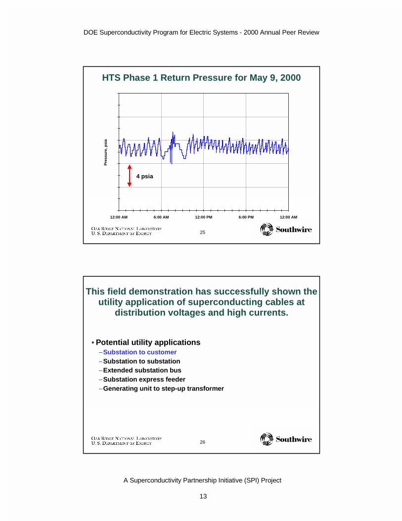
HTS Phase 1 Return Pressure for May 9, 2000
26
This field demonstration has successfully shown theutility application of superconducting cables at
distribution voltages and high currents.
• Potential utility applications–Substation to customer–Substation to substation–Extended substation bus–Substation express feeder–Generating unit to step-up transformer

DOE Superconductivity Program for Electric Systems - 2000 Annual Peer Review
A Superconductivity Partnership Initiative (SPI) Project
14
27
Presentation Outline
• Southwire Activities (David Lindsay, Southwire)– Introduction–30-m Cable Installation–30-m Cable Operation
• FY 2000 Results–30-m Cable Off-Line Testing (Mike Gouge, ORNL)–5-m Cable Research–Component Development–Cryogenic Dielectrics Research (John Stovall, ORNL)
• FY 2000 Performance / FY 2001 Plans• Technology Integration• Summary
28
FY 2000 Objectives for ORNL(from FY 1999 Peer Review)
• Conduct cable bending and short circuit tests on the 5-mcables.
• Continue cryogenic dielectric aging tests.• Assist Southwire with the final construction, installation,checkout, testing, and operation of the SPI 30-m, 3-phaseHTS cable.
• Extend HTS cable capability in partnership withSouthwire researchers by:–developing a cable splice,– improving the cable cryostat cryogenic insulation,–design a cable termination for higher operating voltages, and–examine cryogenic dielectric system requirements for higher
voltage HTS cables.

DOE Superconductivity Program for Electric Systems - 2000 Annual Peer Review
A Superconductivity Partnership Initiative (SPI) Project
15
29
FY 2000 Results
• 30-m Cable Demonstration (Southwire lead)–Assisted Southwire with assembly of 3-phase, 30-m cable (Aug-
Oct 99)–Joint Southwire/ORNL effort in commissioning cable and
cryogenics system (Sep-Dec 99)–Joint Southwire/ORNL effort in 30-m cable demonstration and
tests (dc V-I, ac withstand, temperature and flow scans, etc.)
• 5-m Cable Research (ORNL lead)–successful over-current tests (~10 x) on 5-m cable– impulse tested cable #2 and the terminations to ~ 90 kV
(recoverable breakdown above 90 kV)–bent 5-m cable and tested
30
FY 2000 Results (continued)
• HTS Cable Component Development–design improvements to pressurized termination:
• heat loss reduced• more robust to ambient conditions
–collaboration with NASA Kennedy Space Center Cryogenics TestBed on low thermal loss, flexible cryostats.
–have designed and fabricated a 5-m cable with a splice• developed and successfully tested model dielectric tape splice• will test cold dielectric cable splice next month at ORNL
–cryogenic dielectric aging tests underway–YBCO quench and stability studies

DOE Superconductivity Program for Electric Systems - 2000 Annual Peer Review
A Superconductivity Partnership Initiative (SPI) Project
16
31
First use of HTS cables in an industrial application
ORNL supported the 30-m, 3-phase, HTS cabledemonstration at Southwire
32
ORNL assisted Southwire with the assemblyof 30-m HTS cable terminations in Sept. 1999

DOE Superconductivity Program for Electric Systems - 2000 Annual Peer Review
A Superconductivity Partnership Initiative (SPI) Project
17
33
Commissioning the 30-m cryogenic systemSept. - Oct. 1999
• acceptance testing at Southwirein September 1999.
• commissioning in Oct-Nov 1999
• support of softwaredevelopment for manual andautomatic control functions
• system is quite reliable: minorequipment problems with somecomponents: cryogenic valveactuator, control air compressor
34
Off-line testing of 30-m cables
• High voltage withstand• DC voltage/current tests
–Nov. 1999
• DC current load test• DC voltage/current tests
–June 2000– to determine cable performance after 6
months of operation, after 4 to 6 cool-down and warm-up cycles, and undervariable loading

DOE Superconductivity Program for Electric Systems - 2000 Annual Peer Review
A Superconductivity Partnership Initiative (SPI) Project
18
35
High Voltage Withstand Test - 11/19/99
• Voltage held for 30 minuteson each phase to test cabledielectric system.–Phases 1 and 2 maintained at
166% of rated voltage withoutbreakdown.
–Phase 3 maintained at 230% ofrated voltage withoutbreakdown.
36
Capacitance- nF / m
Phase 1 Phase 2 Phase 3Measured 1.815 1.739 1.265Calculated 1.778 1.778 1.207Difference 2.1% -2.2% 4.8%
Inductance - nH / m
Phase 1 Phase 2 Phase 3Calculated 31.4 31.4 38.2
Above values result in surge impedance for 30-mcable of about 4 ohms.
Measured and Calculated Capacitance

DOE Superconductivity Program for Electric Systems - 2000 Annual Peer Review
A Superconductivity Partnership Initiative (SPI) Project
19
37
V-I curve & DC current load testsNov./Dec. 1999 and June 2000
• Voltage versus current(VI curve) wasmeasured to determinethe resistance of thesuperconducting cablesand terminations.
• DC load current testssimulated– average,– rated, and– emergency loading of
superconducting cables.
38
Off-line average, rated, and emergency dc loadcurrent tests were conducted in Dec. 1999
0
200
400
600
800
1000
1200
1400
1600
11/30/99 12/1/99 12/2/99 12/3/99 12/4/99 12/5/99 12/6/99
Cu
rren
t, d
c am
ps
Phases 3 & 2 Phases 1 & 2 (6 to 8 hours at each dc current)
Phases 1 & 2
52 hours

DOE Superconductivity Program for Electric Systems - 2000 Annual Peer Review
A Superconductivity Partnership Initiative (SPI) Project
20
39
0
0.1
0.2
0.3
0.4
0.5
0.6
0 500 1000 1500 2000 2500
Current (A)
Vo
lts
Phase 3 (Nov 1999)Phase 2 (Nov 1999)Phase 3 (June 2000)Phase 2 (June 2000)linear fit
DC V-I curves in Nov. 1999 and June 2000indicate no change in 30-m cable performance
40
-0 .5
0
0 .5
1
1 .5
2
2 .5
3
3 .5
0 50 0 10 00 15 00 20 00 25 00 30 00 35 00
5 -m an d 3 0 -m C a ble V -I C u rve s @ 77 K
Ic = 10 90 A
n = 3
Ic
= 29 80 A
n = 9
F irs t 5 -m ca b le
F irst p hase o f 30 -m cab le
Testing of 30-m HTS Cables at Carrollton
• Testing was performed on the power and shield conductors in thecable cryostat with boiling liquid nitrogen cooling.
• Performance was as expected from the individual tape properties.

DOE Superconductivity Program for Electric Systems - 2000 Annual Peer Review
A Superconductivity Partnership Initiative (SPI) Project
21
41
End-to-end cable dc resistance has been measured
3 SupplyTerminations
3 ReturnTerminations3 Phase HTS Cable
67 µ ohmsper phase
67 µ ohmsper phase
At 1250 ampsNo dc resistance
At 2500 ampsand 0.25 µV / cm
0.01 µ ohmsper meterper phase
Fixed ResistanceVariable dc Resistance
with distance Fixed Resistance
42
5-m cable research facility at ORNL

DOE Superconductivity Program for Electric Systems - 2000 Annual Peer Review
A Superconductivity Partnership Initiative (SPI) Project
22
43
5-m High Temperature SuperconductingCable Research Facility Status: July 2000
• Facility upgrades complete– impulse power supply upgraded from 100 to 200 kV (BIL tests)–25,000 A pulsed dc power supply commissioned (short circuit
tests)–pressurized terminations: improved cryogenic performance
• Adjacent test stands used for development of HTStapes (BSCCO and YBCO)– large capacity cryocooler with power supplies and data
acquisition for ac loss, stability and quench testing–~ 20 cm warm bore, 6 T magnet (cooled by pulse-tube
cryocooler) for quench and stability studies of HTSconductors
44
Facility upgrade - 200 kV impulse generator

DOE Superconductivity Program for Electric Systems - 2000 Annual Peer Review
A Superconductivity Partnership Initiative (SPI) Project
23
45
5-m HTS cable #2 and terminationswere impulse tested to ~90 kV
• Requirement is 110 kV fordistribution-class cable
• Breakdown above 90 kV does noinsulation damage
• Cable can recover if test voltagereduced to < 90 kV
• Tests indicative of transientbreakdown in long liquid nitrogenpath
• No damage evident in systemwhen disassembled
• Will next test with different cable
46
Facility upgrade - 25,000 A, pulsed dc power supplyfor short circuit testing

DOE Superconductivity Program for Electric Systems - 2000 Annual Peer Review
A Superconductivity Partnership Initiative (SPI) Project
24
47
10 -5
0 .0 001
0 .0 01
0 .0 1
0 .1
1
0 50 10 0 15 0 20 0 25 0 30 0
H T S T a p e R e s is tan c e at C u rr en t pu lse s
R/L
(m
Oh
m/c
m)
I (A )
R /L @ 30 0 K
R /L @ C ritic a l cu r ren t
R /L @ 130 K
Over-current testing of single HTS tapes
• A fault current simulation testwas performed on a single HTStape wound on a rigid former.
• Tape was cooled in an openliquid nitrogen bath.
• Pulsed currents of up to 10 xthe critical current applied forup to 3 seconds.
• At 10 times the design current(each tape @ ~ 120 A), the datashowed that the HTS stillcarries a significant fraction ofthe total current
48
• Figure shows HTS cable and joint voltage in response to a 12.8-kA, 2 sec over-current pulse to simulate a short to ground.
• Cable survived with no performance degradation over-currentsup to 15 kA. Design current is 1.25 kA.
0
2000
4000
6000
8000
10000
12000
14000
-1000
0
1000
2000
3000
4000
5000
6000
0 2 4 6 8 10
HTSC000018I (A)VcbVjt
I (A
)
V (m
V)
Time (s)
Successful short circuit (10x) testof 5-m HTS cable

DOE Superconductivity Program for Electric Systems - 2000 Annual Peer Review
A Superconductivity Partnership Initiative (SPI) Project
25
49
• Bent 5-m cable #2 in bothdirections
• Tested cable after bending todetermine dielectric systemintegrity– ac withstand test successful
5-m HTS cable bending to simulatestorage and shipment after manufacture
50
Second generation pressurized termination (T2)developed
• An innovative new termination has been developed andrefined– the design uses liquid / gaseous nitrogen at few to 10 bar
pressure– the inner and shield conductor cold bushings are eliminated– the vacuum pumping system, system pump-down and leak
checking from the previous vacuum design T1 are eliminatedsimple flange and bus arrangement
– the concept is reliable and uses pressure rated componentsfamiliar to the utility industry
–heat losses have been reduced about a factor of 2 from the 6/99 T2prototype

DOE Superconductivity Program for Electric Systems - 2000 Annual Peer Review
A Superconductivity Partnership Initiative (SPI) Project
26
51
T1:
T2: Neutral bushing Phase bushing
T2 (pressure termination) is more compact than T1 (vacuum termination)
52
Testing of T2 (pressure termination)
• T2 terminations have been through many cooldowncycles both at ORNL and Southwire. Cooldown isefficient with no component being stressed by the rate ofcooldown.
• High current runs:–dc current scans to about 2500 amp on the center conductor.–10 x overcurrent to 13 kA for 2 s
• Performed an ac withstand test at 18 kV ac for 30minutes.
• Impulse tested to ~90 kV.• Measured heat loads and LN pressure drops.

DOE Superconductivity Program for Electric Systems - 2000 Annual Peer Review
A Superconductivity Partnership Initiative (SPI) Project
27
53
0
100
200
300
400
500
T2 (1999), I=1250 A, 5-m
T2 (2000), I=1000 A, 5-m
T2 (2000), I=600 A, 30-m
T2 (1999), I=0 A, 5-m
T2 (2000), I=0 A, 5-m
Hea
t L
oad
(w
att)
Each termination has two leads - phase and neutral
Heat load of terminations has been reduced
54
Cable system heat loss has been measured
3 SupplyTerminations
3 ReturnTerminations3 Phase HTS Cable, 3 cryostats
230 W / termination 230 W / termination
Cable cryostat - 1 W / m / phase
Conductor and Shield0.2 W / m / phase
Fixed Heat LossVariable Heat Loss
with distance and current Fixed Heat Loss
Heat loss (all 3 phases) for 30.5 meter cable and terminations at 600 amps is 1490 W.
690 W 690 W110 W

DOE Superconductivity Program for Electric Systems - 2000 Annual Peer Review
A Superconductivity Partnership Initiative (SPI) Project
28
55
• Testing in progress onsimulated flexible cryostatgeometry.
• Goal is to design flexiblethermal insulation with heatloads approaching rigidcryostat values.
Simulated flexible cryostat testing is beingconducted with NASA Kennedy Space Center
56
Presentation Outline
• Southwire Activities (David Lindsay, Southwire)– Introduction–30-m Cable Installation–30-m Cable Operation
• FY 2000 Results–30-m Cable Off-Line Testing (Mike Gouge, ORNL)–5-m Cable Research–Component Development–Cryogenic Dielectrics Research (John Stovall, ORNL)
• FY 2000 Performance / FY 2001 Plans• Technology Integration• Summary

DOE Superconductivity Program for Electric Systems - 2000 Annual Peer Review
A Superconductivity Partnership Initiative (SPI) Project
29
57
Future location of splice at 30-m test site.
Splice Development and Testing
• A cable splice design hasbeen developed.
• A model cable hassuccessfully tested thedielectric splice design.
• A 5-m splice cable is beingmanufactured bySouthwire for testing atORNL.
• Future plans includetesting a splice on the 30-m cable at Southwire.
58
ConductorGround Shield
Semicon ShieldCryoflex Dielectric
HTS Cable Splice Field enhancement
Stress Cone
A model cable successfullytested the dielectric splice design
• 30 min. ac withstand at 2.5 x operating voltage (18 kV)– Partial discharge level less than 1 pC at 18 kV
• Passed ac voltage breakdown test (10 times rated)• Passed 110 kV BIL impulse test (1.2 x 50 µs )

DOE Superconductivity Program for Electric Systems - 2000 Annual Peer Review
A Superconductivity Partnership Initiative (SPI) Project
30
59
A small model cable dewar has been set upfor and aging studies and partial discharge (PD)
• Dedicated system for agingstudies and PD.
• Automated high pressure LN2fill system installed
• An innovative partialdischarge system has beendeveloped for model cableaging studies–Used to isolate PD signals from
cable test region and stresscones
–Conventional PD detectorsconnected to HV bus havedifficulty locating the source ofPD
60
Aging relationship, t En = Constant
t, Time to Breakdown (days)
10-4 10-3 10-2 10-1 100 101 102 103 104
E,
ac
Ele
ctr
ic F
ield
Str
en
gth
2.4 h 24 h0.2 h 30 years
Operating stress of Southwire 30-m cable
Data Needed
Extrapolated to 30 years
Cryogenic dielectric model cableaging studies are determining cable lifetime

DOE Superconductivity Program for Electric Systems - 2000 Annual Peer Review
A Superconductivity Partnership Initiative (SPI) Project
31
61
ORNL FY 2000 Performance
FY 2000 Plan• Assist Southwire with the final
construction, installation,checkout, testing, andoperation of the SPI 30-m, 3-phase HTS cable.
FY 2000 Performance• 30-m Cable Demonstration
– New cable termination designimproved performance
– Heat load of HTS cable systemestimated during operation
– Voltage withstand test verifiedcable dielectric system and cablecapacitance was measured
– Dc load current tests testedconductors and cryogenicsystem operation off-line
– Dc V-I testing verified health ofmain and shield cableconductors and measured end-to-end resistances (11/99 & 6/00)
– Review of operational data hasshown ways to improve systemperformance.
62
ORNL FY 2000 Performance
FY 2000 Plan
• Conduct cable bending andshort circuit tests on the 5-mcables.
• Continue cryogenic dielectricaging tests.
FY 2000 Performance
• Bent 5-m cable and testeddielectric - passed
• Successful short-circuit tests of5-m cable, no degradation at 15kA
• Impulse tested cable #2 and theterminations
• Measurements suggestdielectric “n” value is inacceptable range
• 30-m cable operating electricstress is very conservative

DOE Superconductivity Program for Electric Systems - 2000 Annual Peer Review
A Superconductivity Partnership Initiative (SPI) Project
32
63
FY 2000 Plan• Extend HTS cable capability in
partnership with Southwireresearchers by:– developing a cable splice,– improving the cable cryostat
cryogenic insulation
FY 2000 Performance• HTS Cable Component
Development– have designed and fabricated a
5-m cable with a splice• developed and successfully tested
model dielectric tape splice• will test 5-m dielectric cable splice
next month at ORNL
– design improvements topressurized termination:
• heat loss reduced• more robust to ambient conditions
– initiated collaboration with NASAKennedy Space CenterCryogenics Test Bed on lowthermal loss, flexible cryostat
ORNL FY 2000 Performance
64
Change in Plans During FY 2000
FY 2000 Plan
• Deferred due to utility interestin applications at distributionvoltages and high currents.– design a cable termination for
higher operating voltages, and– examine cryogenic dielectric
system requirements forhigher voltage HTS cables
FY 2000 Performance
• Added– YBCO quench and stability
studies were initiated
DOE Superconductivity Program for Electric Systems - 2000 Annual Peer Review
A Superconductivity Partnership Initiative (SPI) Project
33
65
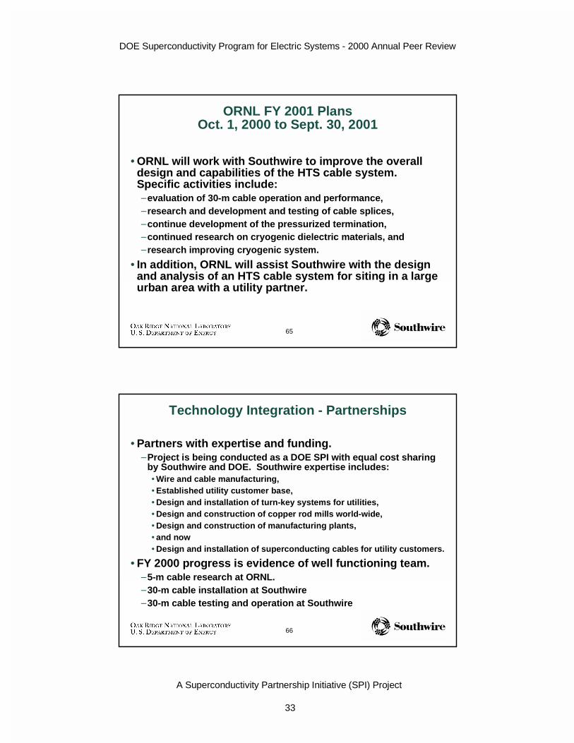
ORNL FY 2001 PlansOct. 1, 2000 to Sept. 30, 2001
• ORNL will work with Southwire to improve the overalldesign and capabilities of the HTS cable system.Specific activities include:–evaluation of 30-m cable operation and performance,–research and development and testing of cable splices,–continue development of the pressurized termination,–continued research on cryogenic dielectric materials, and–research improving cryogenic system.
• In addition, ORNL will assist Southwire with the designand analysis of an HTS cable system for siting in a largeurban area with a utility partner.
66
Technology Integration - Partnerships
• Partners with expertise and funding.–Project is being conducted as a DOE SPI with equal cost sharing
by Southwire and DOE. Southwire expertise includes:• Wire and cable manufacturing,• Established utility customer base,• Design and installation of turn-key systems for utilities,• Design and construction of copper rod mills world-wide,• Design and construction of manufacturing plants,• and now• Design and installation of superconducting cables for utility customers.
• FY 2000 progress is evidence of well functioning team.–5-m cable research at ORNL.–30-m cable installation at Southwire–30-m cable testing and operation at Southwire

DOE Superconductivity Program for Electric Systems - 2000 Annual Peer Review
A Superconductivity Partnership Initiative (SPI) Project
34
67
Technology Integration - Expertise and Facilities
• Efficient use of equipment and personnel betweenORNL/Southwire.–Assembly of 30-m cables has involved a team of ORNL, Southwire
and subcontracted technicians.–Shared use of SW ac power supply, ORNL dc power supply, SW
PD detector.
• Technical capability is being established in industry bysubcontracting for subsystems and components.–Cryogenic system was competitively bid and awarded to U.S.
industry.–Components for terminations are being manufactured by U.S.
industry resulting from competitive request for quotations.–Several key consultants have provided technical expertise and
analysis.
68
Technology Integration - Publications
• Two papers were presented at “1999 Cryogenic Engineering andInternational Cryogenic Materials Conference,” July 12-16, 1999,Montréal, Québec, Canada
• 5-m Single-Phase HTS Transmission Cable Tests• Cryogenic System For A High Temperature Superconducting Power
Transmission Cable
• Four technical presentations/papers will be presented at the“Applied Superconductivity Conference, ASC 2000”, in September2000
• Development and Testing of HTS Cables and Terminations at ORNL• Fault Current Tests of HTS Cable and Tape• Installation And Operation Of The Southwire 30-Meter High-Temperature
Superconducting Power Cable (Invited Paper)• Practical AC Loss and Thermal Considerations for HTS Power Transmission
Cable System
• ORNL Annual Report is available on the web• www.ornl.gov/HTSC/HTSPC-11.pdf

DOE Superconductivity Program for Electric Systems - 2000 Annual Peer Review
A Superconductivity Partnership Initiative (SPI) Project
35
69
Summary
• FY 2000 goals have been achieved–30-m HTS cable has been installed–30-m HTS cable is in operation
• ORNL has provided a breadth of expertise to Southwire–4 ORNL research division’s have contributed this year–Have experimented with BSCCO tapes, 1-m, 5-m, 30-m cables,
dielectric model cables, splice cables, cable joints, cryogenicsystems
–Have conducted a variety of tests: critical current, ac losses, acwithstand, voltage breakdown, impulse strength, partial discharge,short-circuit, dielectric aging, cryogenic heat loads
• The difficult transition from laboratory testing to apractical field application has been completed.
70
World’s First Industrial Field Test of HTS CableDelivers Power To Industrial Customer