
IJESRTijesrt.com/issues /Archive-2016/May-2016/24_ DESIGN AND... · important pre-requisite for any...
13
[Gajender*, 5(5): May, 2016] ISSN: 2277-9655 Impact Factor: 3.785 http: // www.ijesrt.com © International Journal of Engineering Sciences & Research Technology [144] IJESRT INTERNATIONAL JOURNAL OF ENGINEERING SCIENCES & RESEARCH TECHNOLOGY DESIGN AND STRESS STRAIN ANALYSIS OF COMPOSITE SPUR GEAR IN AUTOMOBILE Mr.V.R Gajender * , Prof T. Jeyapoovan * M.Tech, Departement of Mechanical Engineering,Hindustan Institute of Technology and Science,Chennai, India Professor,Departement of Mechanical Engineering Hindustan Institute of Technology and Science,Chennai, India DOI: 10.5281/zenodo.51011 ABSTRACT To Design and draw a spur gear and Analyse the stress distribution of the cast steel and the composite material. Spur gear is one of the most commonly used component in power transmission between two parallel shafts, they are widely used in mechanical power transmission.Engineering components made of composite materials have find increasing applications ranging from space craft to small instruments. Overwhelming advantages such as higher dimensional stability, light weight, and minimal attack by environment when compared with other ordinary cast steel gears. Modern level advanced carbon composite materials have opened a new level of soundless, high resilience, lubricant free and precision gearing in power and motion transmission. A proper understanding and prediction of gear failure is an important pre-requisite for any reliable application. In this project, a spur gear is designed using advanced modelling software (Solidworks) and is meshed and analyzed using analysis software by the application of torque load. Finally, by comparing the analysis result of both composite spur gear and the existing cast steel spur gear. KEYWORDS: Gear, cast steel, carbon fiber, epoxy resin, Ansys software, Solidworks design software. INTRODUCTION Overview of Gears: Gear is one of the most common component which is widely used mechanical power transmission system. A gear or cogwheel has a cut teeth or cogs which mesh with another cutted toothed part to transmit torque. Gears always produce a change in torque which gives a mechanical advantage of controlling the motion or torque, the change of the torque is controlled by their gear ratio. The tooth of the two mating gears should have same shapes ,if two or more meshing gears are working in a sequence then they are called gear train .a gear can also mesh a linear toothed part called rack. The gears are very effective in transmitting power from one shaft to another because of its high degree of reliability and compactness. Now a days the gear technology are widely used in rapid shifts of industries such as automobile manufacturing, shipbuilding and other office works because of its high degree of precession. A gearbox is usually employed for the transmission system to reduce speed, increase speed, change the direction of the motion etc. a gearbox consist of a set of gears of various sizes, shafts and bearings that are mounted in a closed lubricated housing. The purpose of gearbox is to control the input give to it from the engine and give away the required power. In this analysis of the involute spur gears in gear box was studied using a nonlinear FEM. Gears are called positive driver because they are toothed members which transmit torque and motion between two parallel shafts by meshing without any slip. In any pair of gear assembly the smaller gear is called pinion and the bigger one is called gear. When pinion is the driver we get a step down drive in which the output speed will be deceased
Transcript of IJESRTijesrt.com/issues /Archive-2016/May-2016/24_ DESIGN AND... · important pre-requisite for any...

[Gajender*, 5(5): May, 2016] ISSN: 2277-9655
Impact Factor: 3.785
http: // www.ijesrt.com © International Journal of Engineering Sciences & Research Technology
[144]
IJESRT INTERNATIONAL JOURNAL OF ENGINEERING SCIENCES & RESEARCH
TECHNOLOGY
DESIGN AND STRESS STRAIN ANALYSIS OF COMPOSITE SPUR GEAR IN
AUTOMOBILE Mr.V.R Gajender *, Prof T. Jeyapoovan
*M.Tech, Departement of Mechanical Engineering,Hindustan Institute of Technology and
Science,Chennai, India
Professor,Departement of Mechanical Engineering Hindustan Institute of Technology and
Science,Chennai, India
DOI: 10.5281/zenodo.51011
ABSTRACT To Design and draw a spur gear and Analyse the stress distribution of the cast steel and the composite material. Spur
gear is one of the most commonly used component in power transmission between two parallel shafts, they are widely
used in mechanical power transmission.Engineering components made of composite materials have find increasing
applications ranging from space craft to small instruments. Overwhelming advantages such as higher dimensional
stability, light weight, and minimal attack by environment when compared with other ordinary cast steel gears. Modern
level advanced carbon composite materials have opened a new level of soundless, high resilience, lubricant free and
precision gearing in power and motion transmission. A proper understanding and prediction of gear failure is an
important pre-requisite for any reliable application. In this project, a spur gear is designed using advanced modelling
software (Solidworks) and is meshed and analyzed using analysis software by the application of torque load.
Finally, by comparing the analysis result of both composite spur gear and the existing cast steel spur gear.
KEYWORDS: Gear, cast steel, carbon fiber, epoxy resin, Ansys software, Solidworks design software.
INTRODUCTION
Overview of Gears: Gear is one of the most common component which is widely used mechanical power
transmission system. A gear or cogwheel has a cut teeth or cogs which mesh with another cutted toothed part to
transmit torque. Gears always produce a change in torque which gives a mechanical advantage of controlling the
motion or torque, the change of the torque is controlled by their gear ratio. The tooth of the two mating gears should
have same shapes ,if two or more meshing gears are working in a sequence then they are called gear train .a gear can
also mesh a linear toothed part called rack. The gears are very effective in transmitting power from one shaft to another
because of its high degree of reliability and compactness.
Now a days the gear technology are widely used in rapid shifts of industries such as automobile manufacturing,
shipbuilding and other office works because of its high degree of precession. A gearbox is usually employed for the
transmission system to reduce speed, increase speed, change the direction of the motion etc. a gearbox consist of a set
of gears of various sizes, shafts and bearings that are mounted in a closed lubricated housing. The purpose of gearbox
is to control the input give to it from the engine and give away the required power. In this analysis of the involute spur
gears in gear box was studied using a nonlinear FEM.
Gears are called positive driver because they are toothed members which transmit torque and motion between two
parallel shafts by meshing without any slip. In any pair of gear assembly the smaller gear is called pinion and the
bigger one is called gear. When pinion is the driver we get a step down drive in which the output speed will be deceased
[Gajender*, 5(5): May, 2016] ISSN: 2277-9655
Impact Factor: 3.785
http: // www.ijesrt.com © International Journal of Engineering Sciences & Research Technology
[145]
and the torque increases. On the other side, when the gear is the driver it results in step up drive in which the speed
increases and the torque decreases. Basically the output speed and the torque is indirectly proportional to each other.
Now a days the increase in demand for the power transmission in machines, vehicles, elevators and generators has
created grown demand for more precise analysis of the characteristics of gear systems.
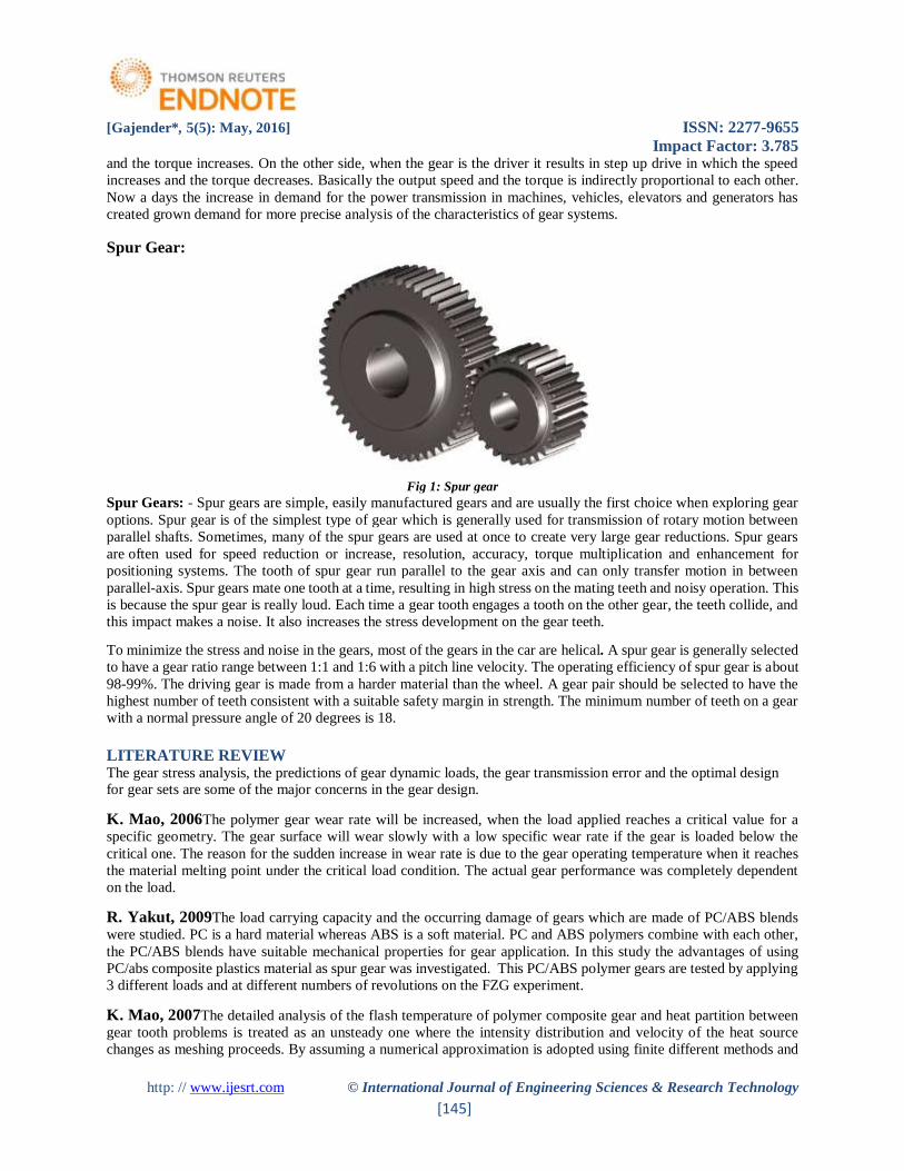
Spur Gear:
Fig 1: Spur gear
Spur Gears: - Spur gears are simple, easily manufactured gears and are usually the first choice when exploring gear
options. Spur gear is of the simplest type of gear which is generally used for transmission of rotary motion between
parallel shafts. Sometimes, many of the spur gears are used at once to create very large gear reductions. Spur gears
are often used for speed reduction or increase, resolution, accuracy, torque multiplication and enhancement for
positioning systems. The tooth of spur gear run parallel to the gear axis and can only transfer motion in between
parallel-axis. Spur gears mate one tooth at a time, resulting in high stress on the mating teeth and noisy operation. This
is because the spur gear is really loud. Each time a gear tooth engages a tooth on the other gear, the teeth collide, and
this impact makes a noise. It also increases the stress development on the gear teeth.
To minimize the stress and noise in the gears, most of the gears in the car are helical. A spur gear is generally selected
to have a gear ratio range between 1:1 and 1:6 with a pitch line velocity. The operating efficiency of spur gear is about
98-99%. The driving gear is made from a harder material than the wheel. A gear pair should be selected to have the
highest number of teeth consistent with a suitable safety margin in strength. The minimum number of teeth on a gear
with a normal pressure angle of 20 degrees is 18.
LITERATURE REVIEW The gear stress analysis, the predictions of gear dynamic loads, the gear transmission error and the optimal design for gear sets are some of the major concerns in the gear design.
K. Mao, 2006The polymer gear wear rate will be increased, when the load applied reaches a critical value for a
specific geometry. The gear surface will wear slowly with a low specific wear rate if the gear is loaded below the
critical one. The reason for the sudden increase in wear rate is due to the gear operating temperature when it reaches
the material melting point under the critical load condition. The actual gear performance was completely dependent
on the load.
R. Yakut, 2009The load carrying capacity and the occurring damage of gears which are made of PC/ABS blends
were studied. PC is a hard material whereas ABS is a soft material. PC and ABS polymers combine with each other,
the PC/ABS blends have suitable mechanical properties for gear application. In this study the advantages of using
PC/abs composite plastics material as spur gear was investigated. This PC/ABS polymer gears are tested by applying
3 different loads and at different numbers of revolutions on the FZG experiment.
K. Mao, 2007The detailed analysis of the flash temperature of polymer composite gear and heat partition between
gear tooth problems is treated as an unsteady one where the intensity distribution and velocity of the heat source
changes as meshing proceeds. By assuming a numerical approximation is adopted using finite different methods and

[Gajender*, 5(5): May, 2016] ISSN: 2277-9655
Impact Factor: 3.785
http: // www.ijesrt.com © International Journal of Engineering Sciences & Research Technology
[146]
the results are shown as close to those found using semi-analytical methods and by assuming no internal hysteresis and the material properties are constant.
J.L. Moya, A.S. Machado, 2007We have performed a theoretical analysis of the procedure to determine the Lewis
Factor and we have also performed the contact analysis of spur gear to find out the stress distribution between the gear teeth’s.
V. Siva Prasad This paper depicts design and stress strain analysis of spur gear and it is proposed to substitute the
metallic gears of sugarcane juice machine with polymer gears to reduce the noise and weight. A virtual model of spur
gear was generated in PRO-E, Model is taken in ANSYS 10.0 for analysis by applying normal load condition. The
main objective of this paper to analysis the different polymer gears namely nylon, polycarbonate and their viability
checked with the counterpart metallic gear like cast iron. Concluding the study using the FEA methodology, it can be
proved that the composite gears, if well designed and analysed, will give the useful properties like as a low cost, noise,
Weight, vibration and perform its operation similar to the metallic gears. Based on the static analysis Nylon gear are suitable for the use of sugarcane juice machine under limited load condition in comparison with cast iron spur gears.
Design of Spur Gear
Module (M)
The module is the ratio between the pitch diameter to the number of teeth. The unit of the module is millimeters.
Below is a diagram showing the relative size of teeth machined in a rack with module ranging from module values of
0.5 mm to 6 mm
Fig 2: Module ranges
NORMAL PRESSURE ANGLE
An important variable affecting the geometry of the gear teeth is the normal pressure angle. This is generally
standardized at 20º. Other pressure angles should be used only for special reasons and using considered judgment.
CONTACT RATIO
The gear design is such that when in mesh the rotating gears have more than one gear in contact and transferring the
torque for some of the time. This property is called the contact ratio. This is a ratio of the length of the line-of-action
to the base pitch.
Design Calculations and Specifications
Specifications
Model = Compact SUV
Engine = Top mounted intercooler, Intercooled, mHawk CRDe, 4 Stroke, Turbo charged, DI
Engine capacity =2179cc
Max. Gross power: 120 bhp (89 kW) @ 4000 rpM
Max. Gross torque: 290 N·m (210 lbf·ft) @ 1800-2800 rpm
Gear Box: 5 speed manual and 6 speed automatic
Front Brakes: Disc & Caliper type, Twinpod & Tandem booster (with anti-lock braking system)
Fuel tank capacity = 60 liters (13 imp gal; 16 US gal)
Tyres = P235/70 R16, Radial Tubeless
Rear Brakes: Drum Type
Front Brakes: Disc & Caliper type, Twinpod & Tandem booster (with anti-lock braking system)
Turning circle radius: 5.6 m (18 ft) for 2WD
Wheel base =105.5 in (2,680 mm)

[Gajender*, 5(5): May, 2016] ISSN: 2277-9655
Impact Factor: 3.785
http: // www.ijesrt.com © International Journal of Engineering Sciences & Research Technology
[147]
Width = 71.5 in (1,816 mm)
Length =176.9 in (4,493 mm)
Height = 77.8 in (1,976 mm)
Curb weight = 5,534 lb. (2510kg) (2WD)
Calculations:
Torque (T) = 25.5kg-m @2500rpm
T = 25.5 kg-m
T = 25.5×10 N-m
T = 225 N-m
T = 2225000 N-mm
N = 2500 rpm.
Power (P) = 2×3.14×2500×T/60
P = 2×3.14×2500×225/60
P = 58875 Watt
Power (P) = 58.875 K Watt.
Torque (T) = F×(d/2)
Where,
F-load,
d- Pitch circle diameter (z×m=170mm)
T= F×(d/2)
F = T/ (d/2)
F = 255000/90
Load (F) = 2833.33N
Using Lewis equation,
Tangential load, F =b×y×pc×σ b
Pc = 3.14×module
Pc = 31.4mm
Y= Lewis form factor=0.134mm
b = face width = 54mm
The maximum allowable stress= 8.7413N/mm2.
Ultimate tensile strength for cast steel = 540Mpa
Allowable stress for cast steel = ultimate tensile strength/3
= 540/3 = 180N/mm2> 8.7413N/mm2
Allowable stress for composite = ultimate tensile strength/3
= 52/3 = 17.33N/mm2>8.7413N/mm2
Ultimate tensile strength for the glass filled polyamide = 38.1Mpa
Allowable stress for composite = ultimate tensile strength/3
= 38.1/3 = 12.7N/mm^2>8.7413N/mm2
So, the design is safe.
Calculations of Gear Tooth Properties
Pitch circle diameter (p.c.d) = z×m = 17×10 = 170mm
Base circle diameter (Db) = D cos α
= 170×cos20
= 159.745mm
Outside circle diameter = (z+2)×m= (17+2)×10 = 190mm
Clearance = circular pitch/20 = 31.4/20 = 1.57mm
Dedendum = Addendum + Clearance = 10+1.57 = 11.57mm
Module = D/Z = 170/17 = 10mm

[Gajender*, 5(5): May, 2016] ISSN: 2277-9655
Impact Factor: 3.785
http: // www.ijesrt.com © International Journal of Engineering Sciences & Research Technology
[148]
Dedendum circle diameter = P.C.D -2×dedendum
= 80-2×11.57= 156.86mm
Fillet radius = Circular pitch/8 = 31.4/8 = 3.9mm
Pitch circle diameter (Pc) = m×z = 10×21 = 210mm
Hole depth = 2.25×m = 2.25×10 = 22.5mm
Thickness of the tooth = 1.571×10 = 15.71mm
Face width (b) = 0.3×210= 63mm
Center distance between two gears = 210mm
Diametral pitch = Number of teeth/P.C.D
= 17/170= 0.1mm
MATERIALS AND METHODS Cast Steel
Cast steel is the first type of steel which allowed alloys to add to the iron. Prior to this method, manufacturers are
unable to get steel hot enough to melt. By heating blister steel in a clay crucible which is placed directly into the fire,
Huntsman allowed the metal to reach upto 2900°F (1600°C). Melting allowed other elements, such as nickel, to be
mixed into the metal, thus strengthening the steel. Cast steel has a harsh surface finish. It regularly has surface openings made by gas rising amid the warming procedure.
A flexible metal, this kind of steel is extremely intense, having four times the elasticity of cast iron. Rigidity is the
amount of weight made by pulling an article and can withstand before it breaks.
One concern when utilizing cast steel is whether the surface gaps stretch out into the inside of the metal. Assuming
this is the case, these gaps could make shortcomings that influence the soundness of the steel. Measuring the volume
of water that can be filled the openings will give a decent sign of whether the gaps reach out far into the metal.
Hardness
The hardness of cast steel differs relying upon the blend of carbon and different fixings. The heat levels utilized when
blending the metal also influence the hardness of the completed metal item. Commonly, bring down levels of carbon
and high compound substance come about a gentler metal. More elevated amounts of carbon with less included permits
accomplishes a cast steel with more prominent hardness yet bring down yield quality, which is the adaptability of the
metal.
Durability
Various tests are used to find out the strength and durability of cast steel before it begin to breakdown. These tests
include drop tests, impact tests, fracture tests and tear tests. In this area low allow concentrations and high carbon are
actually detrimental.
Ductility
The ductility of steel is the measurement of how much shaping or molding it can take and how small the sheets can
become without breaking down. This determines largely by the material mixtures of the cast steel and how it is formed.
In general, tempered or quenched steel has higher ductility levels and the ability to deform without breaking, than
traditional annealed steel, which gives a softer metal.
Fatigue
The fatigue property of cast steel represent how much pressure and use the steel can take before breaking down. The
fatigue property of cast steel shows its predicted life.
Properties of Cast Steel
Density = 7870 kg/m3
Young modulus = 200 GPa
Poisson’s ratio = 0.29
Tensile strength = 518.8 MPa
Ultimate Tensile Strength = 540 MPa
Yield Tensile Strength = 415 MPa
Bulk modulus = 140 GPa

[Gajender*, 5(5): May, 2016] ISSN: 2277-9655
Impact Factor: 3.785
http: // www.ijesrt.com © International Journal of Engineering Sciences & Research Technology
[149]
Composite Material
The composite material can be characterized as a blend of two or a larger number of materials that outcomes in
preferable properties over those of the individual segments utilized alone. Rather than metallic composites, every
material holds its different substance, physical, and mechanical properties.
The two constituents are support and a framework. The primary favorable circumstances of composite materials are
their high quality and solidness, consolidated with low thickness, when contrasted and mass materials, taking into
account a weight lessening in the completed part.
The reinforcing stage gives the quality and firmness. By and large, the fortification is harder, more grounded, and
stiffer than the grid. The reinforcement is typically a fiber or a particulate. Particulate composites have measurements
that are roughly equivalent in all bearings. They might be round, platelets, or whatever other normal or unpredictable
geometry. Particulate composites have a tendency to be much weaker and less firm than consistent fiber composites,
however they are normally substantially less costly.
Carbon Fiber
The main reason for the reinforcement is to give better levels of quality and stiffness than the composite. In a consistent
fiber-reinforced composite, the strands give basically the greater part of the quality and solidness. Indeed, even in
molecule fortified composites, critical changes are gotten.
Carbon strands show direct stretch strain conduct to disappointment, the expansion in quality additionally implies an
increment in the lengthening to-disappointment. The business strands consequently show extensions of up to 2.2%,
which implies that they surpass the strain capacities of ordinary natural lattices.
Carbon strands are accessible from various residential and outside producers in an extensive variety of structures
having an even more extensive scope of mechanical properties. The earliest industrially accessible carbon strands
were delivered by thermal deterioration of rayon antecedent materials. The procedure included exceedingly controlled
strides of thermal treatment and pressure to shape the fittingly requested carbon structure. Carbon filaments are
additionally fabricated from pitch forerunner for forte applications. Pitch fiber properties ordinarily incorporate high
modulus and thermal conductivity.
Fig 3: Carbon fiber
Epoxy Resin
Epoxy resins are frequently used in filament-wound composites and are also suitable for molding prepress. They are
stable to chemical attacks and are excellent adherents having slow shrinkage during curing process and no emission
of volatile gases. These advantages, however, make the use of epoxies rather expensive. Also, they cannot be expected
beyond a temperature limit of 140ºC. They are use in high technology areas where service temperatures are higher, as
a result, is ruled out. Epoxy-reinforced concrete and carbon-reinforced epoxy structures and glass-reinforced are used
in bridge structures and building.
The applications for epoxy-based materials are broad and incorporate coatings, cements and composite materials, for
example, those utilizing carbon fiber and fiberglass reinforcements. The science of epoxies and the scope of financially
accessible varieties permit cure polymers to be created with an extremely expansive scope of properties. As a rule,

[Gajender*, 5(5): May, 2016] ISSN: 2277-9655
Impact Factor: 3.785
http: // www.ijesrt.com © International Journal of Engineering Sciences & Research Technology
[150]
epoxies are known for their incredible bond, substance and thermal resistance, great to-fantastic mechanical properties
and great electrical protecting properties.
Properties of Composites (50% Carbon Fibers in Epoxy Resin Matrix)
Density = 1800 kg/m3
Young modulus = 450 GPa
Poisson’s ratio = 0.30
Tensile strength = 52 MPa
Compressive strength = 600 Mpa
Glass Filled Polyamide
Glass-filled polyamide, or glass-filled plastic, is a mouldable composite material. It contains short glass-strands in a
matrix of a polymer material. It is utilized to fabricate an extensive variety of basic segments by injection or
compression moulding.
Either thermoplastic or thermosetting polymers might be utilized. A standout amongst the most broadly utilized is
nylon. The principal mouldable composite was Bakelite. This utilized wood flour filaments as a part of phenolic pitch.
As the strands were just short this material had moderately low mass quality, yet at the same time enhanced surface
hardness and great mouldability.
An extensive variety of polymers are presently created in glass-filled assortments, including polyamide (Nylon), acetal
homopolymers and copolymers, polyester, polyphenylene oxide (PPO/Noryl), polycarbonate, polyethersulphone
Mass embellishment compound is a pre-blended material of sap and strands supplied for trim. Some are thermoplastic
or thermosetting, others are artificially cured and are blended with an impetus (polyester) or hardener (epoxy) before
moulding.
Properties of Glass Filled Polyamide
Yield Strength: 5910 Mpa
Tensile Strength: 38.1 Mpa
Poisson’s Ratio: 0.314
Mass Density: 840 Kg/m3
Shear Modulus: 3300 Mpa
RESULTS AND DISCUSSION Static Structural Analysis
The static structural analysis calculates the stresses, displacements, strains, and forces in structures caused by loads
that does not induce significant inertia and damping effects. Steady loading and response conditions are assumed; that
the loads and the structure’s response are assumed to change slowly with respect to time. A static structural load can
be performed using the ANSYS WORKBENCH solver. The types of loading that can be applied in a static analysis
include:
a. Steady-state inertial forces
b. Temperature (for thermal strain)
c. Externally applied forces and pressures
d. Imposed displacements (nonzero)
Design software offers a scope of devices to empower the era of a complete advanced representation of the item being
designed. Not withstanding the general geometry apparatuses there is additionally the capacity to produce geometry
of other coordinated outline teaches, for example, mechanical and standard pipe work and finish wiring definitions.
Apparatuses are likewise accessible to bolster community improvement. Various idea plan apparatuses that give in
advance Modern Outline ideas can then be utilized as a part of the downstream procedure of building the item. These
extent from applied Mechanical outline portrays, figuring out with point cloud information and exhaustive freestyle
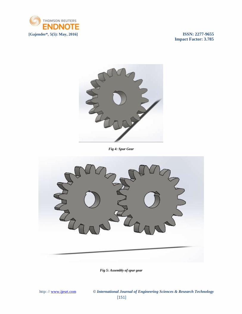
surface instruments. The spur Gear models are made by utilizing Solidworks programming. The models are
demonstrated as follows.
[Gajender*, 5(5): May, 2016] ISSN: 2277-9655
Impact Factor: 3.785
http: // www.ijesrt.com © International Journal of Engineering Sciences & Research Technology
[151]
Fig 4: Spur Gear
Fig 5: Assembly of spur gear

[Gajender*, 5(5): May, 2016] ISSN: 2277-9655
Impact Factor: 3.785
http: // www.ijesrt.com © International Journal of Engineering Sciences & Research Technology
[152]
Analysis Results of Spur Gear in different Materials
Report of cast steel spur gear at TORQUE T=140 Nm
Fig 6: Total deformation in cast steel
Fig 7: Equivalent Elastic Strain of cast steel Fig 8: Equivalent stress of cast steel
[Gajender*, 5(5): May, 2016] ISSN: 2277-9655
Impact Factor: 3.785
http: // www.ijesrt.com © International Journal of Engineering Sciences & Research Technology
[153]
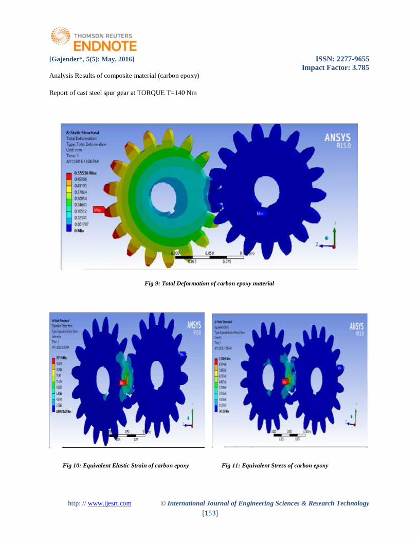
Analysis Results of composite material (carbon epoxy)
Report of cast steel spur gear at TORQUE T=140 Nm
Fig 9: Total Deformation of carbon epoxy material
Fig 10: Equivalent Elastic Strain of carbon epoxy Fig 11: Equivalent Stress of carbon epoxy
[Gajender*, 5(5): May, 2016] ISSN: 2277-9655
Impact Factor: 3.785
http: // www.ijesrt.com © International Journal of Engineering Sciences & Research Technology
[154]
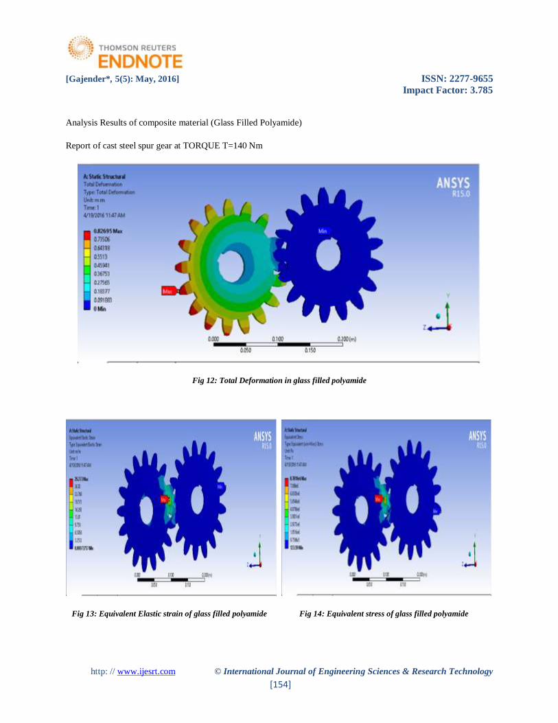
Analysis Results of composite material (Glass Filled Polyamide)
Report of cast steel spur gear at TORQUE T=140 Nm
Fig 12: Total Deformation in glass filled polyamide
Fig 13: Equivalent Elastic strain of glass filled polyamide Fig 14: Equivalent stress of glass filled polyamide

[Gajender*, 5(5): May, 2016] ISSN: 2277-9655
Impact Factor: 3.785
http: // www.ijesrt.com © International Journal of Engineering Sciences & Research Technology
[155]
Tables:
Table 1:. Comparison of various properties of the materials
Cast steel Composite (Carbon) Difference
Torque (T) 140Nm 170Nm 140Nm 170Nm
Total Deformation 1.1101 1.601 0.55536 1.122 0.55474
Equivalent Elastic strain 36.57 59.933 20.759 39.921 15.811
Equivalent Stress (von-Mises) 7.314e6 1.077e7 4.3417e6 9.413e6 2.973e6
Max Shear Elastic Strain 66.341 80.204 31.002 58.214 35.339
Max Shear Stress 8.471e6 9.122e6 5.368e6 6.101e6 3.103e6
Table 2:. Comparison of various properties of the materials
Cast steel Composite (GFP) Difference
Torque (T) 140Nm 170Nm 140Nm 170Nm
Total Deformation 1.1101 1.601 0.8269 1.324 0.2832
Equivalent Elastic strain 36.57 59.933 29.273 46.482 7.297
Equivalent Stress (von-Mises) 7.314e6 2.077e7 5.7818e6 1.013e7 1.5322e6
Max Shear Elastic Strain 66.341 80.204 44.346 69.682 21.339
Max Shear Stress 8.471e6 9.122e6 6.062e6 8.756e6 2.409e6
[Gajender*, 5(5): May, 2016] ISSN: 2277-9655
Impact Factor: 3.785
http: // www.ijesrt.com © International Journal of Engineering Sciences & Research Technology
[156]
CONCLUSION The literature survey of the composite gear was performed. The study in stress distribution and weight reduction of
spur gear for composite materials and cast steel has been done.
On the basis of the study, the analysis of both composite materials and cast steel are analyzed in the application of
gear box which is used in automobile vehicles. From these analysis we found the stress values for composite materials
is less as compared to the cast steel spur gear.
So from the analysis results, we conclude that, the stress induced, deformation and weight of the composite spur gear
is less as compared to the cast steel spur gear and followed by Glass filled polyamide. So, Composite materials are
capable of using in automobile vehicle gear boxes instead of existing cast steel gears with better results.
ACKNOWLEDGEMENTS The authors would like to acknowledge the support of CAD Lab, Department of Mechanical Engineering ,Hindustan
Institute of Technology and Science,Chennai,Tamilnadu,India.
REFERENCES
[1] K. Mao, A new approach for polymer composite gear design, Mechanical Engineering, School of
Engineering and Design,Brunel University, Uxbridge, UK 2006.
[2] N.A. Wright, S.N. Kukureka, Wear testing and measurement techniques for polymer composite gears, School
of Materials and Metallurgy, The University of Birmingham, Edgbaston ,UK,2001.
[3] K. Mao, A numerical method for polymer composite gear flash temperature prediction, Mechanical
Engineering, School of Engineering & Design Brunel University, Uxbridge, Middlesex UB8 3PH, UK,2007.
[4] V. Siva Prasad, Syed Altaf Hussain, V.Pandurangadu, K.Palani Kumar, Modeling and Analysis of Spur Gear
for Sugarcane Juice Machine under Static Load Condition by Using FEA, International Journal of Modern
Engineering Research (IJMER), Vol.2,2004.
[5] S. Kirupasankar, C. Gurunathan, R. Gnanamoorthy, Transmission efficiency of polyamide nano composite
spur gears, Indian Institute of Information Technology, Design & Manufacturing (IIITD&M) Melakottaiyur,
Chennai 600 048, India,2010.
[6] J.L. Moya, A.S. Machado A new approach for polyamide composite gear design,2007.
[7] R.Yakut, H.Duzcukoglu, M.T.Demirci Mechanical Education Department, University of selcuk, Campus,
Konya, Turkey,2009.