
Architecture of Solar Energy - CURVE | Carleton University ... · Architecture of Solar Energy ......
56
Architecture of Solar Energy appropriating photovoltaic technology for the design of sustainable buildings by Gandhi Habash A thesis submitted to the Faculty of Graduate and Postdoctoral Affairs in partial fulfillment of the requirements for the degree of Master of Architecture Carleton University Ottawa, Ontario © 2017 Gandhi Habash
Transcript of Architecture of Solar Energy - CURVE | Carleton University ... · Architecture of Solar Energy ......

Architecture of Solar Energy appropriating photovoltaic technology for the design of sustainable buildings
by
Gandhi Habash
A thesis submitted to the Faculty of Graduate and Postdoctoral Affairs
in partial fulfillment of the requirements for the degree of
Master of Architecture
Carleton University
Ottawa, Ontario
© 2017
Gandhi Habash

II
Abstract
Renewable energy is part of a 21st century sustainability paradigm that responds to
environmental degradation, forming western society’s existential concern for earth- often
referred to as the ‘green’ movement. New tools and technologies, both for building design
and construction, have come to assist architects in the creation of buildings that produce
their own energy and which consume less of it. Renewable energy production strategies
are necessary in order to mitigate the issue of future energy security, as traditional sources
of fuel become increasingly scarce. This thesis presents a proposal for a building that can
produce power by incorporating a photovoltaic and thermal energy collection system as a
programmed design component, offering an architectural solution to what is traditionally
viewed as an engineering problem. From this perspective renewable energy systems can
be integrated as both functional and aesthetic elements within buildings.

III
Acknowledgments
I would like to thank my advisor Stephen Fai for his guidance and direction throughout the
development of this thesis, and Scott Bucking for his insight in the area of building
integrated photovoltaics.
I am also grateful for the encouragement of my classmates and coworkers, many of whom
have become lifelong friends during this journey.
And finally, to my parents Riadh and Najat: your unfading interest in, and support of, my
passion for architecture has been the greatest inspiration of all.

IV
Contents
Abstract
I I
Acknowledgments
I I I
Table of contents
IV
List of f igures
V
List of tables VI List of acronyms and definitions VII 1 Introduction
11
1.1 Sustainability ............................................................................................ 11 1.2 Photovoltaics ............................................................................................ 13
2 Literature Review
17
2.1 Form and Function ................................................................................... 17 2.2 Effects of Heat on Performance .............................................................. 18 2.2.1 Double Skin Facades .................................................................... 19 2.3 Adaptive Facades ..................................................................................... 20 2.4 Building Precedents ................................................................................. 21
3 Methodology
26
3.1 Site Selection and Building Program........................................................ 26 3.2 Defining Size ............................................................................................. 32 3.3 Building Form ........................................................................................... 33

IV
3.3.1 Optimization for Energy Capture................................................. 33 3.3.2 Building Plan and Section ............................................................ 37 3.3.3 Incorporation of Passive Strategies ............................................. 42 3.3.4 Estimating Electricity Generation Potential ................................ 48
4 Conclusions and Recommendations
50
4.1 Technical Challenges ................................................................................ 51 4.2 Design Challenges .................................................................................... 51 4.3 Sustainability ............................................................................................ 52
Bibliography 54

V
List of Figures
1.1
Windcatcher in Yazd, Iran ............................................................................... 12
1.2 Diagram showing components of a Photovoltaic Array .................................
13
1.3 Traditional Methods of Integrating PV Systems .............................................
14
2.1 Annual Sum of Irradiation by Geographic Area ..............................................
17
2.2 ETFE BIPV Systems ..........................................................................................
19
2.3 Ventilated BIPV Cavity Wall Systems ..............................................................
20
2.4 ASF System Module and Array ........................................................................
21
2.5 BIPV Façade and Skylight on a Skyscraper in Seoul, South Korea ..................
22
2.6 Low Energy Office Building in Aarhus, Denmark ............................................
23
2.7 Office Building for a Law Firm in Copenhagen, Denmark ..............................
23
2.8 Faceted BIPV/shading system .........................................................................
24
2.9 ETFE BIPV Façade on the U.S. Chancery in London, United Kingdom ...........
25
3.1 Context Plan ....................................................................................................
27
3.2
Rendezvous Lebreton Group’s Winning Proposal for Lebreton Flats’ Masterplanning ...............................................................................................
28
3.3
Site Photos .......................................................................................................
30
V
3.4 45 Parliament Street Data Centre ...................................................................
30
3.5 Functional Program of a Typical Data Centre .................................................
31
3.6 Volumetric Studies ..........................................................................................
35
3.7 Volumetric Studies - Sawtooth Facade ...........................................................
35
3.8 Aerial Perspective of Proposed Building .........................................................
36
3.9 Southeast Elevation of Proposed Building ......................................................
36
3.10 Perspective Showing the Interior Lobby Space ..............................................
38
3.11
Perspective Showing the Proposed Building in Context ................................ 39
3.12 Sections Through Proposed Building ..............................................................
39
3.13 Plans of Proposed Building..............................................................................
40
3.14 Plans of Proposed Building..............................................................................
41
3.15 Prevailing Winds in the Ottawa Region During 2013 .....................................
42
3.16 Section Perspective showing Multiple-Inlet System ......................................
43
3.17 Exterior Perspective showing Multiple-Inlet System ......................................
44
3.18 Exterior Perspective showing Multiple-Inlet System ......................................
45
3.19 Exterior Perspective showing Multiple-Inlet System ......................................
46
3.20 Building Section ............................................................................................... 47
3.21 Plan Highlighting Surfaces Exposed to Varying Levels of Irradiation ............. 48

VI
List of Tables
3.1 Cabinet Power Density and Heat Load ..............................................................
32
3.2 Size and Capacity of Various Canadian Data Centres .......................................
33
3.3 Orientation for Maximum Annual Energy Production in 10 Canadian Cities ...
34
3.4 Yearly PV Potential of Major Canadian Cities and Cities Worldwide ................
49

VII
List of Acronyms and Definitions
Acronyms
AC Alternating Current
ASF Adaptive Solar Facade
ASHRAE American Society of Heating, Refrigerating and Air-Conditioning Engineers
a-Si Amorphous Silicon Photovoltaic Cell
BIPV Building Integrated Photovoltaics
c-Si Crystalline Silicon Photovoltaic Cell
DC Direct Current
DHW District Hot Water System
ETFE Ethylene Tetrafluoroethylene
HVAC Heating, Ventilation and Air Conditioning
NCC National Capital Commission
NRCAN Natural Resources Canada
OPV Organic Photovoltaic Cell
OJVF Open Joint Ventilated Facade
PV Photovoltaics
VCS Ventilated Core Slab

VII
Definitions
Capacity Factor
the ratio of actual electrical energy output over a given period of time to the maximum possible electrical energy output over the same period
Insolation solar radiation that reaches the Earth’s surface
Irradiance the radiant flux (power) received received by a surface per unit area
Temperature Coefficient
figure that represents the power output loss of a photovoltaic cell for every °C increase in surface temperature; figure is unique to each type of PV cell

1 Introduction
1.1 Sustainability
Technological advances in the global age have transformed previously local economies into
an international consumer culture. Governments rely on the employment and services
associated with both upstream and downstream economies in order for their social
systems to remain viable (Harris, 535-538), hurtling societies toward crisis levels of
overpopulation and pollution. Consumerism as a dominant global social force has
increased pollution, necessitating the invention of various means by which to manage its
quantifiable environmental impact. Since buildings are the greatest consumers of energy,
architects have been tasked with generating solutions for more resource and energy
efficient designs at all scales. Naturally, this calls into question what such typologies ought
to look like, or whether their sustainable quality can or should be visually expressed at all.
For centuries prior to the invention of modern building climate control systems, substantial
architectural elements such as wind catchers (figure 1.1) were used to ventilate and cool
buildings in hot and arid or humid areas. Such technologies are still used today in parts of
the Middle East and North Africa, and similar solutions have been integrated into net-zero
and net-positive buildings throughout Canada. New technologies are often designed and
integrated alongside historic ones to create novel solutions for age-old problems, as well
as for emerging ones.

12
Source: Dehghani-Sanij, A.r., M. Soltani, and K. Raahemifar. "A New Design of Wind Tower for Passive Ventilation in Buildings to Reduce Energy Consumption in Windy Regions." Renewable and Sustainable Energy Reviews 42 (2015): 182-95. Web.
Figure 1.1: (left) basic airflow through a windcatcher; (right) windcatcher in Yazd, Iran
When it comes to the power of the sun, mankind has always sought to harness its energy
for everyday needs. It has been an important resource and challenge for designers, faced
with balancing natural lighting with the risk of overheating. Passive solar design seeks to
reduce the energy consumption of buildings as well as produce ones that act in conjunction
with natural forces, not against them. Active solar energy systems are a relatively new area
in architecture; building-integrated photovoltaic (BIPV) electric power systems are a major
new technology in current practice, particularly as they relate to energy performance. Such
systems have become more sophisticated and not only produce electricity, but can also be
substantial functional and decorative building elements. The design and performance
potential of BIPV systems are being taken more seriously as the technology becomes
cheaper and more efficient. For example, a BIPV double-skin facade is an integral
component of the building envelope as well as a solar electric energy system that
generates power, preheats ventilation air, and protects from sound, wind, and pollutants
which make life in urban areas less comfortable. Such systems are therefore
multifunctional construction materials with both passive and active elements.
Woodrow W. Clark II highlights the Green Industrial Revolution in his book, Global Energy
Innovation. He remarks on how it is about more than just renewable energy systems and
storage technologies, noting that such systems have to be “combined and integrated in
order to be more conversational and efficient as well as reducing the carbon and emissions
in the global atmosphere.” It is in such a context that architects must incorporate

13
appropriate technologies like photovoltaics into the design of their buildings, yet not
ignore the merits of historic precedents. New technologies should enhance and not
replace or obfuscate pre-existing ones.
1.2 Photovoltaics
The standard element of a BIPV system is the photovoltaic (PV) module, composed of
individual solar cells. These are strung together with cables and wires to form a PV array
(figure 1.2). Direct or diffuse sunlight shining on the cells induces the photovoltaic effect,
generating unregulated DC electric power. DC power can be used directly, stored into a
battery system, or fed into an inverter that transforms and synchronizes the power into AC
electricity. The electricity can be used within the building or exported to a utility company
through a grid interconnection.
Source: www.pure-eie.com
Figure 1.2: diagram showing components of a photovoltaic array
There are four main types of photovoltaic cells that are commercially available: amorphous
silicon (a-Si); monocrystalline silicon (c-Si); polycrystalline silicon (c-Si); and hybrid cells. a-
Si cells are flexible and are more efficient under higher temperatures due to annealing
effects, while overall they are less efficient (6-8%) and costlier than both types of crystalline
silicon cells. a-Si, in contrast to c-Si solar cells, are more environmentally friendly as they
do not contain toxic heavy metals such as cadmium or lead. The choice of material depends
on the architectural solution for an application. Whereas a-Si cells are flexible and can be
applied to a variety of geometries, crystalline cells are rigid and have to be installed as
faceted components. The trade-off is that c-Si cells are almost twice as efficient as a-Si cells
(13-16%). An alternative type of thin film product is the organic photovoltaic cell (OPV).

14
With efficiencies as high as 22%, they are competitive in performance with traditional
crystalline cells, with the benefit of being highly flexible, extremely thin, and uniform in
appearance. Organic cells also have the potential of being inexpensive to manufacture,
however the technology is still relatively young and not yet commercially available;
presently organic cells have a much shorter operational lifespan than inorganic (silicon)
products (Lin et al. 133-56).
Photovoltaic systems can be integrated into buildings in three ways. The most common
method is to simply add commercially available modules onto exterior surfaces; this is
often the case in retrofit projects where photovoltaic panels are laid out on commercial
rooftops or on the sloped roofs of single family homes. The second method involves the
integration of the same commercially available modules within building surfaces; in such
cases, the photovoltaic panels can act as both a weather barrier as well as an active energy
production component. The third and most fully integrated solution involves making the
modules into building components. An example of this type of solution are the solar glass
shingles introduced by Tesla in 2016. Tesla’s product directly addresses the issue of
aesthetics, camouflaging the actual solar cell when viewed from acute angles (e.g. as an
onlooker on ground level); the solar cell itself is only visible at perpendicular angles (when
viewed directly overhead). All three of these methods (figure 1.3) face the same design
and performance challenges.
Source: www.pure-eie.com
Figure 1.3: traditional methods of integrating PV systems

15
Varieties of BIPV systems are available, however most can be grouped into two primary
categories: roof and façade systems. Façade systems include curtain wall products,
spandrel panels and individual glazing units. Roof systems include tiles, shingles and
skylights. Aside from ready-made commercial products, PV modules can also be designed
as aesthetically integrated building components as well as entire structures. When
compared with large scale PV solar farms, BIPV can sometimes be the optimal method of
installing renewable energy systems, particularly in areas where undeveloped land is
scarce, expensive, or inaccessible.
This thesis does not necessarily propose a fourth method of integration, but rather
considers issues beyond the technology itself in order to enhance a potential project of
architecture. This goes beyond existing methods that are almost always an engineering
solution, merely a direct application of existing technology. From an architectural
perspective, designs have to be naturally integrated, visually exceptional, and more
desirable when compared with existing ones. Renewable technologies cannot appear as
though they were put together from a ‘kit of parts.’ A novel approach is necessary in order
for photovoltaics to be successfully integrated into buildings. They can only be included in
projects if architects have sufficient knowledge about the technology and have access to
appropriate design tools to assist them. Based on these requirements, architects have to
approach building design completely differently than in traditional practice.
Picon states that we “still bear the imprint of modernist prejudices,” in the sense that
modern architects generally tend to dismiss the performativity of décor, as it seems less
important than structural or energetic behaviour. When considering buildings that
incorporate sustainable technologies and construction methods, their design is not strictly
a question of performance or aesthetics. As Picon suggests, the visual expression of
ornament is often fundamental to the performance of such buildings, and also serves to
describe their purpose. As argued in section 3, an architecture of solar energy is both about
the visual expression of technology as well as the development of a novel typology that

16
exists solely due to internal and external factors that originated during the late 20th and
early 21st centuries. The project of architecture discussed in this section will help define
how one may approach the design of such a typology. As the incorporation of such
technologies becomes more commonplace, researchers, manufacturers, service providers,
and fabricators will take solar technology more seriously as a proper building material,
catalyzing further development in the area.

`
2 Literature Review
2.1 Form and Function
Irradiation is the single most important factor affecting PV performance, determined by
the local climate and site location (figure 2.1) as well as by the array’s surface tilt and
orientation. Maximum annual performance of grid-connected PV generators is obtained
with modules tilted at an angle equal to the site latitude, facing the equator. The total solar
radiation availability directly affects the PV generator’s annual energy yield.
Source: SolarGIS
Figure 2.1: global map showing annual sum of irradiation by geographic area
When all photovoltaic modules are on the same plane, estimating their annual energy
production (kWh/kWp/year) can be highly accurate. Estimation becomes more difficult as
BIPV systems become increasingly accepted by architects and builders, since irregular and

18
curved shapes will be desired. Partial shading as a result of complex geometry is a design
issue which can lead to performance losses. Urbanetz et al. found that a curved PV array
on a parking shade structure was 10% less efficient than a flat rooftop array on the same
site, due to shading. Consequently, compromises between the aesthetics (form) and
energy production (function) expected from a BIPV system will have to be reached. In the
case of Urbanetz et al., a 10% loss can be considered acceptable since the curved design is
more visually and functionally appealing for the desired application.
2.2 Effects of Heat on Performance
Solar irradiation is more critical in determining the maximum temperature of PV modules
than the outdoor air temperature. Depending on the material of PV cells, efficiency
reduction due to overheating can be partially alleviated through the integration of a
thermal collection system. Such systems absorb much of the heat gained by PV panels
through a heat transfer fluid in an open-loop (air) or closed loop (liquid) configuration. The
benefits are twofold: collecting more energy and lowering the temperature of PV modules.
In such situations, BIPV/T systems are more cost effective (Chen et al. 1894-1895). The
collected heat can be used for space heating or district hot water (DHW) heating either by
direct means or through a heat pump. Chen et al. incorporated a ventilated core slab (VCS)
in the basement of a single family dwelling, utilizing the collected heat as means to warm
the hollow-core slab. Chen et al. also found that wind has the most significant cooling
effect, whereas mechanical ventilation had a negligible effect; for every 1km/h increase in
wind speed, the temperature in the air cavity was reduced by 2 degrees due to convective
heat transfer.
While higher temperatures generally result in the reduced performance of PV modules, a-
Si cells perform more optimally under higher temperatures due to the annealing effect of
the material (Hu et al. 50). Amorphous silicon cells offer the added benefit of flexibility and
can be integrated into the design of curved geometries, like those of ETFE cushion systems.
ETFE BIPV systems also offer the potential to harvest thermal energy between the top and

19
bottom layers (within the air cavity), while producing energy and offering ample daylight
to the contained spaces. The Japanese Pavilion at Expo 2010 (figure 2.2, left) incorporates
a-Si modules on its cushions’ extreme outer surfaces. Such applications are not ideal since
high temperatures affect the inflation of the skin, compromising the overall structure.
Experiments conducted on a full-scale testbed in China show that integrating photovoltaic
cells on an intermediate layer mitigates the temperature effects on the structure (Hu et al.
42-45).
Source: (left) www.inhabitat.com; (right) Kieran Timberlake Architects. United States Chancery, London. 2017. Artist’s Concept. US Department of State. Washington, DC.
Figure 2.2: (left) ETFE BIPV system with a-Si PV cells applied to extreme inner surface; (right) façade integrated ETFE BIPV system using crystalline PV cells
2.2.1 Double Skin Facades
Double skin ventilated facades offer interesting potential in both the design and
performance of BIPV systems: its thermal buffer zone reduces the cooling load during
summer months, preventing heat from entering directly through the building envelope;
during winter months, the system can be used to preheat ventilation air, thereby reducing
the heating load (Agathokelous et al. 745-746). The captured thermal energy can also be
exhausted and/or circulated, drawing colder air up the wall assembly- particularly useful
for cooling photovoltaic panels since PV efficiency is reduced under high temperatures.
There are two types of ventilated facades; a traditionally ventilated air chamber is only
open to the exterior at the top and bottom (figure 2.3, left), while open joint ventilated
facades (OJVF) incorporate a series of thin gaps that allow exterior air to enter and exit the

20
cavity along the wall or roof assembly (figure 2.3, right). OJVFs are desirable in climates
with hot summers and mild winters, since surface temperatures are higher.
Source: eSim conference paper
Figure 2.3: (left) single inlet BIPV/T system; (right) multiple inlet BIPV/T system
Recent studies have also analyzed OJVF performance in cold climates. Yang et al. showed
that a multiple cavity wall assembly increases the thermal efficiency of a BIPV/T system in
a cold climate by up to 7% when compared to a single cavity system. By countering the
effect of temperature stratification, the heat within the cavity is evenly distributed and
therefore minimizes temperature variation among the PV panels; this facilitates the
estimation of energy production. Moreover, a uniform and reduced temperature slows the
degradation of PV modules, extending their operational lifespan. From an architectural
perspective, the size and location of the air gaps, along with the length and shape of PV
panels, has a direct effect on the air collection rate within the cavity, and ultimately system
design and performance.
2.3 Adaptive Facades
Adaptive Solar Facades (ASF) are modular, dynamic building facades. The basic element of
the ASF is a dynamic, multifunctional module which can act autonomously or in a cluster
(figure 2.4). Each module is essentially a miniaturized solar tracker. Dynamic facades have
the potential to increase the efficiency of BIPV systems by as much as 10 to 25%
(depending on geographic location and design) since individual modules can be raised and
twisted in order to maximize direct exposure to solar radiation. Furthermore, they can add

21
to the architectural expression of a building. While ASFs are a novel solution to optimize
panel orientation, they also pose several challenges, particularly in northern climates.
Aside from being slightly more expensive than fixed systems, their more complex
technology, consisting of several moving parts, can affect the reliability of their operation.
During winter, icing on the actuators can completely inhibit the system’s functionality.
Costs associated with de-icing and regular maintenance can erase much of the financial
value gained from the system’s increased energy production.
Source: eSim conference paper
Figure 2.4: (left) individual module for an ASF system; (right) an array as part of an ASF system
2.4 Building Precedents
Most built examples of façade-integrated photovoltaic systems simply replace vision or
spandrel glass with PV modules (figures 2.5, 2.6). These designs rely on the respective
buildings’ large vertical surface area to help compensate for a reduced power output, a
result of less than optimal orientation. Given the relatively low efficiency of PV systems
(between 15-20%), especially when considering the loss in DC to AC conversion (10% of
the total system loss), it is not good practice to attribute a loss of output to poor design.
Photovoltaics are often implemented in such a manner because the solution employs
standardized PV modules of nominal size. PV modules exist in a typically flat and
rectangular form factor because it offers an efficiency in their manufacture, reducing cost.
While this reason is valid from a basic economic perspective, it limits the design potential
available to architects, as well as the performance potential in building projects that do not

22
lend themselves to a straightforward application of such solutions, particularly when
aesthetics are valued and site conditions are constrained.
Source: Adrian Smith Gordon Gill Architecture. Federation of Korean Industries. 2013. Photograph. Federation of Korean Industries. Seoul.
Figure 2.5: (left) BIPV Façade on a skyscraper in Seoul, South Korea; (right) image of same building showing BIPV skylight and façade
The Federation of Korean Industries building in Seoul, South Korea demonstrates a
straightforward design and application of various BIPV systems. Due to the functional
concerns associated with the leasing and occupancy of high-rise office towers, the
dimension within which its BIPV façade could have been designed was constrained both in
depth as well as in expression. Since views out of the offices are valued and a rectangular
floorplate is required, the architects simply tilted and substituted what would normally be
infill spandrel panels with c-Si PV modules. Such a strategy only marginally increases
system efficiency. On another portion of the building, c-Si cells are used as shading devices
as well as on-site power generators on a skylight assembly.
The municipal office building in Aarhus, Denmark shown in figure 2.6 incorporates several
types of photovoltaic modules within the expression of its façade. Similar to the Korean
example, spandrel panels are substituted with tilted c-Si panels in between glazed
segments. Elsewhere on the façade, a shading system incorporates solar cells in a
horizontal pattern, breaking up what would otherwise be a monotonous, flat wall.

23
Source: C.F. Møller Architects. Low Energy Office Building. 2010. Photograph. Aarhus Municipality. Aarhus.
Figure 2.6: low energy office building in Denmark incorporating a variety of BIPV solutions
Source: Mørk, Adam. Horten Headquarters, 3XN Architects. 2009. Photograph. Carlsberg Ejendomme. Copenhagen.
Figure 2.7 façade designed to reduce internal heat gain
While not a BIPV façade, the envelope for a law firm’s headquarters in Copenhagen,
Denmark elegantly combines ornament and functionality. Its faceted, folded pattern is
designed such that all glazed surfaces are oriented to the north, minimizing solar heat gain
within the building. The glazed portions also face a canal, therefore the building is not only
oriented for optimal efficiency, but is also designed to offer its users the best views of its
surroundings. The façade is also novel in material composition, employing the use of
fiberglass instead of steel framing. Its method of construction is technologically
sophisticated and innovative in its modular assembly, yet simple in the sense that the
issues it mitigates are age-old. In this case, the solution is more architectural than it is
technological. The architecture itself is the primary contributor to the energy savings and

24
sustainable quality of the building. Simultaneously, the three-dimensional relief of the zig-
zag pattern creates visual interest; from the south, the façade appears to be completely
solid (figure 2.7, right); from the north, the folded pattern of glass and travertine cladding
becomes distinct (figure 2.7, left). It is a far more elegant solution to shutting out excessive
sunlight when compared with traditional methods that include, among others: aluminum
awnings; brise-soileil; window tints; window films.
Source: Coop Himmelb(l)au. House of Music II. 2014. Photograph. North Jutland House of Music Foundation. Aalborg.
Figure 2.8: (left) faceted BIPV/shading system; (right) detailed view of solar PV shading system
Musikkens Hus (figure 2.8) in Aalborg, Denmark incorporates solar PV panels within the
geometry of aluminum solar shading devices on the building’s southern façade. It is not
clear whether the inspiration for the faceted forms came prior to or after the incorporation
of the PV cells, however the result is both visually interesting and functional.
WKieran Timberlake’s design for the United States chancery in London (Figure 2.9)
incorporates crystalline cells behind a veil of ETFE foils draped along a second skin,
outboard of the glazed building envelope. Since the ETFE foils are not inflated, the use of
c-Si cells does not affect the system’s structural integrity. As a result, the design mitigates
wind downdrafts, generates energy, and reduces internal heat gain in one fell swoop- an
elegant solution to several common problems faced by office buildings. It is noteworthy,
however, that the application of a BIPV system in London’s often overcast and rainy climate
may not be the most cost effective method of pursuing goals in energy efficiency.

25
Source: Kieran Timberlake Architects. United States Chancery, London. 2017. Artist’s Concept. US Department of State. Washington, DC.
Figure 2.9: (left) artist’s concept of ETFE PV double skin façade; (right) detail showing connection with inner glazed surface

3 Methodology
3.1 Site Selection and Building Program
In order to begin the investigation both the building typology and site were chosen very
early in order to account for fixed variables that include climatic and urban qualities,
factors contributing greatly toward determining the appropriate building form. The design
project started with the search for a large site featuring largely unobstructed exposure to
sun and prevailing winds. There are several greenfield and brownfield sites in Ottawa that
satisfy this basic criteria, however Lebreton Flats was chosen because of a recent
competition for its redevelopment and the consequential effect it will have on the city’s
peripheral downtown core.
In order to develop a building proposal, a need for the site’s use had to be identified. The
program had to be sufficiently large in mass in order to explore the thesis question, yet
significant such that it offer something substantial to the city. A critical analysis of Lebreton
Flats in its present and potential future conditions led to the choice of a data centre as the
primary use for the proposed building. The federal government (Shared Services Canada)
is consolidating its data facilities from 258 to 7, reducing its real estate footprint from
600,000ft2 to 180,000ft2; the chosen site at Lebreton is strategically located in proximity to
federal office buildings on both sides of the Ottawa River, and is therefore an ideal location
for one such facility. As a result, pedestrian access, proximity to public transportation, and
parking will be required. Based on this criteria the location is further justified (figure 3.1)

27
not only due to it being within the federal office precinct, but also in its adjacency to the
city’s light rail trunk line. This is resonant with the notion that data centres are considered
core elements of ‘smart’ cities and are necessary technological infrastructure for the
foreseeable future. Consequently, the proposed building program becomes relevant at
both the municipal and federal levels. As means to maximize the potential of the
investigation, a secondary program consisting of various performing arts and civic amenity
spaces is incorporated within the building. By integrating utility and public space, the
design potential and performance of the overall renewable energy system is enhanced,
allowing for synergetic relationships to exist between form and program.
Figure 3.1: context plan showing the chosen site, outlined in red
There are immediate and ongoing plans for the Flats’ redevelopment. A catastrophic fire
in 1900, bureaucratic fumbling, and issues related to contamination halted development
on Lebreton Flats for decades. The winning proposals for its masterplan by Claridge (2004)
and RendezVous LeBreton Group (2016) have proposed what is essentially a residential
neighbourhood, though a variety of smaller public buildings and outdoor spaces are
scattered throughout- including a large stadium (figure 3.2). In contrast, both the Gréber
Report (circa 1950) and National Capital Commission (NCC) 2005 federal land use plan
called for a variety of programming that are still not only municipally relevant, but
nationally significant since the property is immediately adjacent to the capital’s ceremonial

28
route. The former industrial and residential properties on Lebreton Flats were
expropriated by the NCC in the early 1960s and subsequently demolished in order to fulfill
what the Gréber report mandated- buildings and monuments of ‘national significance.’
The winning schemes are at odds with the mid-century masterplan and development thus
far. Based on the city’s soft residential market and current condominium development on
nearby Chaudière Island, the proposed program is arguably stronger and more relevant to
Lebreton’s storied identity than the 2004 and 2016 schemes.
Source: The National Capital Commission
Figure 3.2: RendezVous LeBreton Group’s winning proposal (2016) for the masterplanning of Lebreton Flats’ remaining undeveloped portions; (outlined in red) the chosen location for the proposal
From a morphological perspective, the size of and typology of the proposed building is in
keeping with the spirit of its immediate surroundings. The Canadian Museum of War
(Moriyama Teshima, 2005) is immediately across the road from the site, and the Holocaust
Monument (Studio Libeskind, 2017, seen in figure 3.2) is currently under construction on
the opposite corner. Both structures are equally striking and feature agonized, angular
forms juxtaposed against the flat landscape. They are also culturally significant

29
monuments, therefore the proposal for another physically and programmatically unique
building is arguable and fitting within such a context. Though not adjacent to Lebreton, the
Library and Archives Canada building is prominently located on an escarpment that
overlooks the Flats, and the site for the new main branch of Ottawa Central Library also
overlooks Lebreton; a data centre for the federal government is an appropriate
counterpoint to these institutions.
The choice of an appropriate location for a data centre is influenced by several factors,
particularly the method and purpose of its operation. They are typically located in
proximity to power grids, telecommunications infrastructure, transportation lines, as well
as their users. These are all factors which affect risk, security, and privacy- critical to such
facilities since governments and corporations depend on their ceaseless and reliable
operation in order to conduct business. Data centres do not only act as repositories for
digital information, they are also mission critical components of various enterprises.
Further to security concerns, climate is also a factor in the selection of a building site; cold
climates are favoured since they offer a source of free cooling. Owing to these
requirements, there are several precedents for data centres in urban locations (table 3.1),
however none feature building integrated renewable energy systems, including
photovoltaics.
The closest and most comparable facility is located in downtown Toronto (figure 3.4). The
TR2 Equinix data centre is one of two colocation spaces (the other being TR1) that serve
many of the city’s financial services and financial exchange customers, as well as other
enterprises in the downtown core. It is a mere two kilometers away from the majority of
its clients. By virtue of the financial industry’s time sensitive, secure nature, the facility is a
24 hour, 365 day a year, secure operation. The older Equinix facility, TR1, is within walking
distance of Toronto’s major financial institutions. Both facilities are connected through
fibre optics in order to provide a fast and secure connection.

30
Figure 3.3: (top) site photo looking south-east; (bottom) site photo looking south-west
Source: WZMH Architects. 45 Parliament Street Data Centre. 2013. Photograph. Urbacon Data Centre Solutions Incorporated. Toronto.
Figure 3.4: 22,000m2 Equinix data centre in Toronto’s distillery district

31
Programmatically, data facilities are relatively straightforward in their layout (figure 3.5),
however they have a degree of flexibility in built form that is conducive to the integration
of building integrated photovoltaics: single or multi-storey format; varying slab-to-slab
heights and wall types; structural grid, building envelope and foundation design; raised
floor design; secure vehicular access.
Source: Harrison, Jim. Data Centres: An Introduction to Concepts and Design. N.p.: n.p., 2012. Print.
Figure 3.5: functional program of a typical data centre, showing relationship between spaces and paths of circulation

32
3.2 Defining Size
Data centres have a high power density and heat load, normally expressed in kW and W/m2
per rack, respectively (table 3.1). Comparable facilities to the size proposed by Shared
Services Canada were summarized and average figures were derived based on the findings
(table 3.2) in order to facilitate the estimation of size and energy consumption values for
the building.
Density
Heat Load per rack (kW)
Power Density (W/m2)
Typical Cooling Medium
Cooling Systems
Low Density 1-7 500-900 Air CRAC or CRAH units All-air Systems
Medium Density 8-10 10-14
900-1500 Air CW/refrigerant/carbon dioxide
Hot or cold aisle containment Containment and in-row liquid cooling
High Density 15-24 5000+ CW/refrigerant/carbon dioxide
Cabinet/rear door liquid cooling
High Density plus+ 25+ 8000+ CW/refrigerant/carbon dioxide
Cabinet/rear door liquid cooling
CRAC: computer room air conditioning; CRAH: computer room air handling; CW: chilled water
Source: Harrison, Jim. Data Centres: An Introduction to Concepts and Design. N.p.: n.p., 2012. Print.
Table 3.1: guidance on power density and heat load of cabinets, based on average performance across a number of installations
Maximizing efficiency within a building’s energy load is the first step toward developing a
design for a BIPV application. For a data centre, this involves specifying low energy HVAC
systems, as well as incorporating passive cooling systems and strategies into its design; the
racks have a significant heat load (table 3.1) which require enormous amounts of cooling,
resulting in a large quantity of electricity used for climate control systems. Data centre
operators that advertise ‘green’ or ‘low energy’ facilities typically use evaporative or liquid
cooling systems, both of which are major consumers of potable water resources. The use
of water- a scarce resource which itself requires electricity for treatment- for energy use
reduction is simply not the right approach. Furthermore, evaporative cooling systems have
been identified as major contributors to sick building syndrome, therefore requiring
supervision and regular maintenance- adding cost. This is where using renewable energy
33
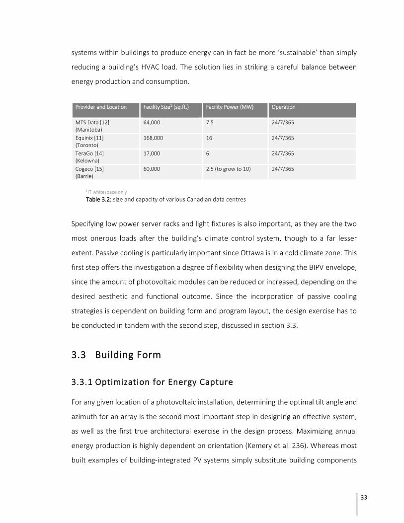
systems within buildings to produce energy can in fact be more ‘sustainable’ than simply
reducing a building’s HVAC load. The solution lies in striking a careful balance between
energy production and consumption.
Provider and Location Facility Size1 (sq.ft.)
Facility Power (MW) Operation
MTS Data [12] (Manitoba)
64,000 7.5 24/7/365
Equinix [11] (Toronto)
168,000 16 24/7/365
TeraGo [14] (Kelowna)
17,000 6 24/7/365
Cogeco [15] (Barrie)
60,000 2.5 (to grow to 10) 24/7/365
1IT whitespace only
Table 3.2: size and capacity of various Canadian data centres
Specifying low power server racks and light fixtures is also important, as they are the two
most onerous loads after the building’s climate control system, though to a far lesser
extent. Passive cooling is particularly important since Ottawa is in a cold climate zone. This
first step offers the investigation a degree of flexibility when designing the BIPV envelope,
since the amount of photovoltaic modules can be reduced or increased, depending on the
desired aesthetic and functional outcome. Since the incorporation of passive cooling
strategies is dependent on building form and program layout, the design exercise has to
be conducted in tandem with the second step, discussed in section 3.3.
3.3 Building Form
3.3.1 Optimization for Energy Capture
For any given location of a photovoltaic installation, determining the optimal tilt angle and
azimuth for an array is the second most important step in designing an effective system,
as well as the first true architectural exercise in the design process. Maximizing annual
energy production is highly dependent on orientation (Kemery et al. 236). Whereas most
built examples of building-integrated PV systems simply substitute building components
34
with PV modules, this investigation conceptualizes a design that considers issues of site
and program in order to inform and maximize the design and performance of the BIPV
envelope. Manipulating building form and/or building components are the simplest
methods of adjusting orientation, since the proposed building is entirely new construction
with few site constraints. This exercise involves an optimization of form for passive cooling
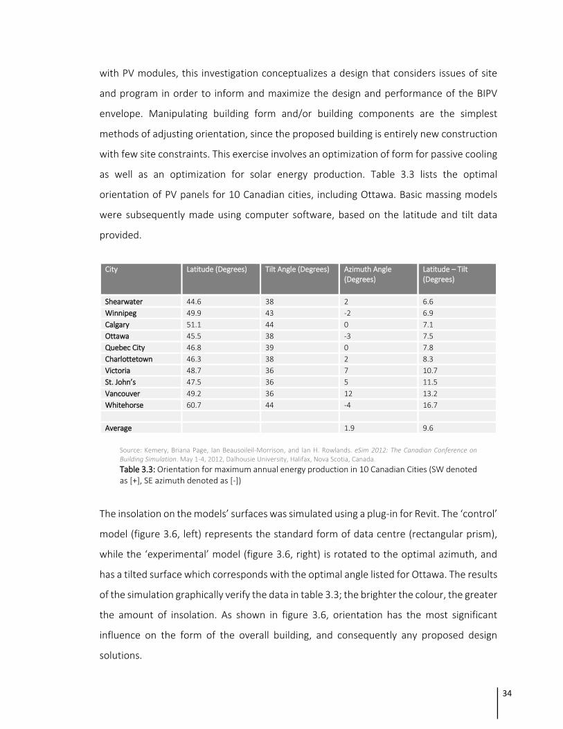
as well as an optimization for solar energy production. Table 3.3 lists the optimal
orientation of PV panels for 10 Canadian cities, including Ottawa. Basic massing models
were subsequently made using computer software, based on the latitude and tilt data
provided.
City
Latitude (Degrees) Tilt Angle (Degrees) Azimuth Angle (Degrees)
Latitude – Tilt (Degrees)
Shearwater 44.6 38 2 6.6
Winnipeg 49.9 43 -2 6.9
Calgary 51.1 44 0 7.1
Ottawa 45.5 38 -3 7.5
Quebec City 46.8 39 0 7.8
Charlottetown 46.3 38 2 8.3
Victoria 48.7 36 7 10.7
St. John’s 47.5 36 5 11.5
Vancouver 49.2 36 12 13.2
Whitehorse 60.7 44 -4 16.7
Average 1.9 9.6
Source: Kemery, Briana Page, Ian Beausoileil-Morrison, and Ian H. Rowlands. eSim 2012: The Canadian Conference on Building Simulation. May 1-4, 2012, Dalhousie University, Halifax, Nova Scotia, Canada.
Table 3.3: Orientation for maximum annual energy production in 10 Canadian Cities (SW denoted as [+], SE azimuth denoted as [-])
The insolation on the models’ surfaces was simulated using a plug-in for Revit. The ‘control’
model (figure 3.6, left) represents the standard form of data centre (rectangular prism),
while the ‘experimental’ model (figure 3.6, right) is rotated to the optimal azimuth, and
has a tilted surface which corresponds with the optimal angle listed for Ottawa. The results
of the simulation graphically verify the data in table 3.3; the brighter the colour, the greater
the amount of insolation. As shown in figure 3.6, orientation has the most significant
influence on the form of the overall building, and consequently any proposed design
solutions.

35
Figure 3.6: (left) volume representing a rectangular prism; (right) volume with south façade tilted at 38 degrees; yellow represents highest levels of irradiance, grey represents lowest levels
Throughout the early exercises of form exploration it became clear that practical changes
to geometry (i.e. forms initially designed to capture a greater amount of solar energy) had
significant potential to become programmatic and decorative elements within the overall
scheme for the building. For example, increasing the surface area of the exterior building
envelope (figure 3.7, left) while also tilting the façade (figure 3.7, right) produces an
interesting design that also generates more energy. These investigations informed
subsequent massing studies that eventually became the design for the project of
architecture, seen in figure 3.8.
Figure 3.7: (left) sawtooth exterior skin pattern tilted at 90°; (right) sawtooth exterior skin tilted at 38°; orange represents highest levels of irradiance, grey represents lowest levels
The design for the building’s mass first addressed the issue of accommodating its physical
program as well as the challenge of capturing solar energy. This required the allocation of
space for a double skin envelope with a minimum height of 16 meters, and a depth varying
between 1-2 meters, based on both the programmatic and technical requirements of the
building typology and technology, respectively.

36
Envisioned is a three-part building; the southern volume (figure 3.9, far left) contains the
data facility as well as a performing arts hall on its uppermost level- it is the building’s
largest physical component and greatest energy producer; the northern volume (figure
3.9, far right) replaces a bandshell platform for Ottawa’s annual Bluesfest with indoor and
outdoor theatres; the northern and southern volumes are connected by a bridge (figure
3.9, center) that spans a five lane parkway, connecting the inland and waterfront portions
of Lebreton Flats. Overall, the building reads as a singular form that sweeps across the
landscape, oriented to capture the greatest amount of solar energy while sheltering its
occupants from Ottawa’s prevailing winds- particularly strong due to the site’s adjacency
and exposure to the river.
Figure 3.8: aerial perspective of the massing for the project of architecture
Figure 3.9: southeast elevation of the proposed building
The building’s curved and tilted surface sweeps along all sides, varying in depth and height,
depending on orientation. From a performance perspective, a curved outer envelope
increases the surface area exposed to the sun and mitigates the potential for snow
accumulation that could potentially obscure the photovoltaic panels; when compared to a
rectangular prism, the curved form is more efficient.

37
3.3.2 Building Plan and Section
Experientially and aesthetically, the envelope contributes to the character of the interior
and exterior spaces of the structure and is deep enough to be inhabitable; on the
northeastern side of the building, the space in between the inner and outer layers contains
a semi-covered pedestrian footbridge that traverses the five lane parkway. It is a
distinguished feature on all levels, seamlessly connecting both sides of the building, seen
in plan (figures 3.13 and 3.14).
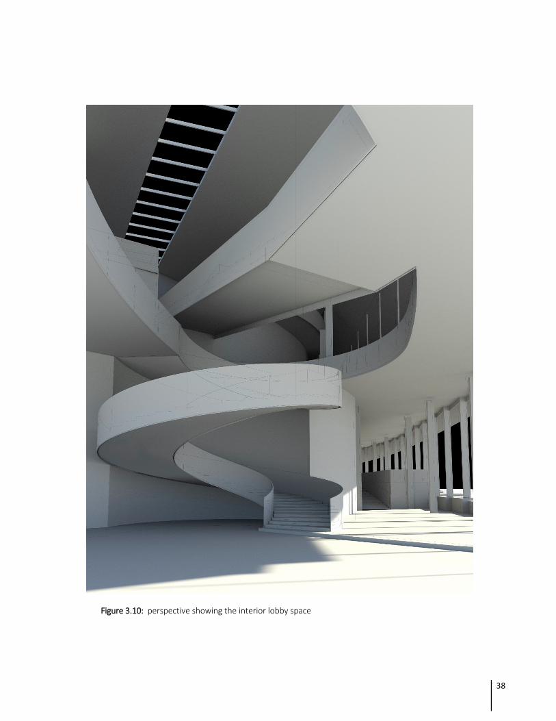
38
Figure 3.10: perspective showing the interior lobby space

39
Figure 3.11: perspective from Albert Street showing the proposed building in context; (foreground) new light rail station under construction; (background) the Canadian War Museum
The sweeping roof is prominent within all publicly accessible spaces, informing visitors of
its unique function, visible in section (figure 3.12). The resulting design demonstrates a
direct relationship between form, program and function.
Figure 3.12: (top) north-south section through data centre and third level performing arts hall, showing bridge (center) and bandshell (far left); (bottom) east-west section through the bandshell and ground level performing arts hall

40
Figure 3.13: (top) ground floor plan showing bandshell, public lobby, performing arts, and data halls; (bottom) second floor plan showing public lobby, bridge, performing arts, and data halls

41
Figure 3.14: (top) third floor plan showing performing arts hall; (bottom) roof plan

42
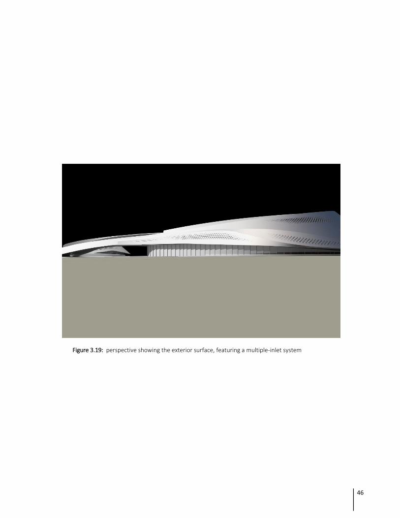
3.3.3 Incorporation of Passive Strategies
Ottawa is in ASHRAE climate zone 6; wind conditions and snow cover both have the
potential to increase energy production and reduce energy consumption, depending on
the design of the building and its envelope. Due to its high albedo, snow cover in proximity
to photovoltaic modules on the exterior surface can increase their energy production by
up to 10% (Norton et al. 1639), compensating for reduced daylight hours during winter
months. Because of this, the outer skin is designed to be proximal to potential snow cover
on the landscape surrounding the building (figure 3.17), thereby capturing ground
reflected diffuse irradiance. Furthermore, the hardscape immediately adjacent to the
building is designed with light coloured material, imitating the effect of snow during non-
winter seasons.
Source: the City of Ottawa Terms of Reference
Figure 3.15: prevailing winds in the Ottawa region during 2013
Wind also contributes toward higher levels of energy production due to its significant
cooling effects. Consequently, the panels for the exterior envelope are envisioned as both
passive and active elements. High temperatures reduce the efficiency of PV modules; since
wind has a far greater cooling effect than forced air systems, a multiple-inlet BIPV/T system
is proposed for the exterior envelope. Individual panels are twisted to varying degrees in
order to optimize airflow behind them, and through the double skin façade. Multiple inlets
are integrated along certain portions of the northwestern and southwestern facades
(figures 3.16-19) since they have the greatest exposure to the sun’s peak hours of

43
insolation, as well as the city’s fastest prevailing wind directions (figure 3.15). Such systems
have been proven to counter the effect of temperature stratification (Yang et al. 2066),
lowering PV temperatures along the path of the air channel, increasing the efficiency of
the system by up to 7%. Segments of the façade that are not susceptible to higher
temperatures are designed to incorporate a single cavity system, since the extra ventilation
is not needed to mitigate issues related to heat.
Figure 3.16: section perspective showing the exterior surface, featuring a multiple-inlet system

44
Figure 3.17: perspective showing the exterior surface, featuring a multiple-inlet system

45
Figure 3.18: perspective showing the exterior surface, featuring a multiple-inlet system
46
Figure 3.19: perspective showing the exterior surface, featuring a multiple-inlet system

47
Figure 3.20: section showing the relationship between the exterior skin and the interior spaces

48
3.3.4 Estimating Electricity Generation Potential
The total surface area of the proposed building envelope is 7900m2, 3500m2 (roughly 50%)
of which is designed to incorporate photovoltaics. PVs are proposed to be located only on
the southern and western surfaces, since they are exposed to the highest levels of solar
irradiance (figure 3.19, portions coloured in orange and yellow). The curved envelope is
rationalized with a faceted, rectangular pattern that can accommodate both rigid and
flexible photovoltaic material; as illustrated in section 3.3.3, the faceted surface
incorporates both flat and torqued panels, each requiring a different material. Roughly 1m2
in surface area each, the panels are hypothetically rated at 1kW per unit. According to
NRCAN’s photovoltaic potential and insolation dataset (table 3.4), the mean yearly energy
production potential for each panel in Ottawa is 1198kWh. Based on this figure, the
system’s total capacity is conservatively estimated to be 3.5MW, capable of powering 388
single family homes annually (based on a consumption of 10,800kWh/yr per household).
Comparatively, the nearby Chaudière Falls hydroelectric power plant has a capacity of
5MW, although it produces a greater amount of electricity since it is operational 24/7, as
opposed to a photovoltaic installation that only produces power during daylight hours.
Figure 3.21: plan highlighting surfaces exposed to varying levels of irradiation, annually

49
Major Canadian Cities and Capitals
Yearly PV Potential (kWh/kW)
Major Cities Worldwide
Yearly PV Potential (kWh/kW)
Regina (SK) 1361 Cairo, Egypt 1635
Calgary (AB) 1292 Capetown, South Africa 1538
Winnipeg (MB) 1277 New Delhi, India 1523
Edmonton (AB) 1245 Los Angeles, U.S.A. 1485
Ottawa (ON) 1198 Mexico City, Mexico 1425
Montreal (QC) 1185 Regina, Canada 1361
Toronto (ON) 1161 Sydney, Australia 1343
Fredericton (NB) 1145 Rome, Italy 1283
Quebec (QC) 1134 Rio de Janeiro, Brazil 1253
Charlottetown (PE) 1095 Beijing, China 1148
Yellowknife (NT) 1094 Washington, D.C., U.S.A. 1133
Victoria (BC) 1091 Paris, France 838
Halifax (NS) 1074 St. John’s, Canada 933
Iqaluit (NU) 1059 Tokyo, Japan 885
Vancouver (BC) 1009 Berlin, Germany 848
Whitehorse (YT) 960 Moscow, Russia 803
St. John’s (NL) 933 London, England 728
Source: National Resources Canada (2007). Photovoltaic potential and solar resources maps of Canada.
Table 3.4: Yearly PV Potential of Major Canadian Cities and Cities Worldwide
The effect of temperature on photovoltaic energy production is inextricably connected to
the estimation of system potential, and by extension, the physical design of a BIPV
envelope. A reference temperature of 25°C is typically used as a standard for solar PV
module laboratory tests, and any change in temperature above or below this figure either
increases or decreases the efficiency of a PV cell. The loss or increase in efficiency, defined
as the temperature coefficient, is a number that can be determined by referring to
manufacturers’ product data, as each photovoltaic panel will be unique. For example, if a
150W panel has a temperature coefficient of -0.40%/°C, operation at 40°C would result in
an output reduction of 9%. On the other hand, output is increased in temperatures below
25°C (positive coefficient value). This is why BIPV applications in cold climates is desirable,
since the added efficiency helps offset the reduced production due to fewer sunlight hours
during winter months.

50
4 Conclusions and Recommendations
This research has explored how photovoltaic technology can be integrated within a
building envelope in order to generate power while simultaneously enhancing the spatial,
aesthetic, and functional qualities of a project of architecture. The design for a BIPV façade
presented as part of this research demonstrates how a practical technology can be
adapted and integrated critically and creatively in order to address new and age-old
challenges related to issues of human comfort and sustainability- the result of a rigorous
design process.
The site selection for the project catered to the functional requirements of photovoltaic
technology, informing the choice of a data centre as the primary building program. This
lent itself to a highly fluid and flexible design process, maximizing the potential for the
envelope to become an engaging building element in its own right. The resulting design
integrates utility and community space within a single footprint, responding to site-specific
conditions as well as the geometry of the envelope. While not designed as a solar farm,
the capacity of the proposed PV system is comparable to that of a small hydroelectric
power plant, proving how BIPV applications at a certain scale are functionally feasible.
Consequently, its formal expression is symbolic of the age of sustainable development and
information technology within which it has been designed, contributing to a visual history
and culture that is in its early years of evolution.

51
4.1 Technical Challenges
Despite its potential to meaningfully inform the design of a building, photovoltaic
technology is itself the most significant limitation to any building integrated application.
The method of manufacturing individual crystalline cells, for example, is limited by the
chamfered square form of the ingot that has to be sliced into usable wafers. This influences
the design of panels since it is more space-efficient to use square forms as opposed to any
other geometry; using a triangular shape represents a loss in surface area that could
otherwise be used for additional cells, consequently producing more electricity.
Site constraints have the greatest potential to influence the integration of photovoltaics
on any given building, particularly those located in urban areas where access to sunlight is
restricted, or those located in areas with challenging climates. This research did not
investigate the potential structural issues associated with freeze-thaw cycles in the
Canadian climate, where the project is speculatively located. Ice build-up, melt, and re-
freeze on exterior surfaces affect the feasibility of any proposed geometry for both
individual panels as well as the overall form; in the case of this research, these panels are
assumed to be smooth. Testing various geometries for panels, perforations, louvres, and
vents is required in order to further develop the potential for such an application to
perform as intended, under real world conditions.
4.2 Design Challenges
As is the case with most unconventional and novel designs, trade-offs will have to be made
in terms of balancing marketable sales features with the sometimes unmarketable
sustainable features of a building. An office tenant may be unwilling to sacrifice even the
most compromised views for the sake of lower utility bills, despite increasingly expensive
electricity prices, which may well strengthen the argument for BIPV applications; the
potential purchaser of a condominium dwelling may be equally unwilling to sacrifice views,
unless the design of a BIPV façade enhances the privacy of the space or its spatial quality,
as demonstrated in the project presented in section 3.
52
Integrating photovoltaic technologies within buildings is not necessarily formulaic or
straightforward. Depending on the type of building (commercial, residential, institutional,
etc.), locating photovoltaic panels on non-optimal surfaces- at non-optimal tilt and rotation
angles- can in fact be more energy efficient than PV applications designed strictly to
capture the maximum amount of irradiation. For example, a residential building that
undergoes peak operations early in the morning and late in the afternoon can be more
efficient with BIPV applications on its east and west façades, despite lower levels of total
annual irradiation. During peak levels of irradiation at mid-day, south facing panels will
overproduce and therefore waste energy, unless it is stored for later use. Even so, the
storage of excess power is often prohibitively expensive and impractical due to battery
systems’ relative inefficiency, not to mention the cost associated with constructing physical
space to store them. Applications of photovoltaic technology within such typologies will
result in characteristically different formal expressions than the one presented as part of
this research, the result of another design approach altogether. This broadens the notion
of what kind of aesthetic an ‘architecture of solar energy’ has, or ought to have.
4.3 Sustainability
However limitless a source of power, the materials and systems used for the capture of
solar energy are themselves not yet renewable; the embodied energy associated with their
design and production is high. Until these components are made to be renewable, solar
energy’s classification as a sustainable source of power remains challenged and requires
further development.
At the moment the majority of BIPV and PV applications within buildings are crude and can
sometimes present challenges at the municipal level in terms of rezoning and development
approvals; government officials and local residents often have an adverse reaction to the
aesthetics of such installations. As the incorporation of renewable energy technologies
such as photovoltaics become more common within buildings, researchers,
manufacturers, service providers, and fabricators will take solar technology more seriously

53
as a proper building material, catalyzing further technological development in the area and
eventually overcoming such barriers, entering into mainstream application.

Bibliography
ASHRAE, 2009, -ASHRAE Handbook of Fundamentals, American Society of Heating, Refrigerating and Air-Conditioning Engineers, Atlanta, GA, USA Agathokleous, Rafaela A., and Soteris A. Kalogirou. "Double Skin Facades (DSF) and Building Integrated Photovoltaics (BIPV): A Review of Configurations and Heat Transfer Characteristics." Renewable Energy 89 (2016): 743-56. Web. Chen, Yuxiang, A.k. Athienitis, and Khaled Galal. "Modeling, Design and Thermal Performance of a BIPV/T System Thermally Coupled with a Ventilated Concrete Slab in a Low Energy Solar House: Part 1, BIPV/T System and House Energy Concept." Solar Energy 84.11 (2010): 1892-907. Web. Chen, Yuxiang, Khaled Galal, and A.k. Athienitis. "Modeling, Design and Thermal Performance of a BIPV/T System Thermally Coupled with a Ventilated Concrete Slab in a Low Energy Solar House: Part 2, Ventilated Concrete Slab." Solar Energy 84.11 (2010): 1908-919. Web. Clark, Woodrow W., and Grant Cooke. Global energy innovation: why America must lead. Santa Barbara, CA: Praeger, 2012. Print. Dehghani-Sanij, A.r., M. Soltani, and K. Raahemifar. "A New Design of Wind Tower for Passive Ventilation in Buildings to Reduce Energy Consumption in Windy Regions." Renewable and Sustainable Energy Reviews 42 (2015): 182-95. Web. Harrison, Jim. Data Centres: An Introduction to Concepts and Design. N.p.: n.p., 2012. Print. Harris, John. "Consumerism." International Social Work 47.4 (2004): 533-42. Web. Hu, Jianhui, Wujun Chen, Deqing Yang, Bing Zhao, Hao Song, and Binbin Ge. "Energy Performance of ETFE Cushion Roof Integrated Photovoltaic/thermal System on Hot and Cold Days." Applied Energy 173 (2016): 40-51. Web. Hu, Jianhui, Wujun Chen, Qiyao Cai, Chengjun Gao, Bing Zhao, Zhenyu Qiu, and Yegao Qu. "Structural Behavior of the PV–ETFE Cushion Roof." Thin-Walled Structures 101 (2016): 169-80. Web.

Hu, Jianhui, Wujun Chen, Bing Zhao, and Hao Song. "Experimental Studies on Summer Performance and Feasibility of a BIPV/T Ethylene Tetrafluoroethylene (ETFE) Cushion Structure System." Energy and Buildings 69 (2014): 394-406. Web. Jonathan Stoller. "Why cold Canada is becoming a hot spot for data centres." The Globe and Mail. Special to Globe and Mail Update, corrected, 2013. Web. 20 Sep. 2016. Kemery, Briana Page, Ian Beausoileil-Morrison, and Ian H. Rowlands. eSim 2012: The Canadian Conference on Building Simulation. May 1-4, 2012, Dalhousie University, Halifax, Nova Scotia, Canada.
Lin, Ching-Fuh, Su, Wei-Fang, Wu, Chih-I, Cheng, and I-Chun. Organic, Inorganic and Hybrid Solar Cells. N.p.: John Wiley & Sons, 2012. Print. Picon, Antoine. Ornament: the Politics of Architecture and Subjectivity. Somerset: Wiley, 2014. Print. Pizzini, Sergio. Advanced silicon materials for photovoltaic applications. Chichester: John Wiley & Sons, 2012. Print. Randall, Julian. Designing Indoor Solar Products. N.p.: John Wiley & Sons, 2005. Print. The Globe and Mail. "A telecom nerve centre to a nation." The Globe and Mail. The Globe and Mail, 2012. Web. 20 Sep. 2016. "Data Centre Consolidation." Government of Canada, Shared Services Canada. N.p., n.d. Web. 20 Sep. 2016. "Data centre design and engineering - Toronto and Montreal examples." Canadian Consulting Engineer. N.p., n.d. Web. 20 Sep. 2016. "Data Centres Canada - Mississauga - TeraGo Networks." TeraGo. N.p., n.d. Web. 20 Sep. 2016. "Downtown Toronto Data Centre features." UDCS. N.p., n.d. Web. 20 Sep. 2016. "How many BTUs are equivalent to 1 ton of cooling capacity?" Reference. N.p., n.d. Web. 20 Sep. 2016. "Low to High Density Cooling - A Flexible Data Centre Solution." Low to High Density Cooling - A Flexible Data Centre Solution | BladeRoom.com. N.p., n.d. Web. 20 Sep. 2016. "Toronto Colocation Provider." Toronto Data Centers | Premium Toronto Colocation by Equinix. Yang, Tingting, and Andreas K. Athienitis. "Performance Evaluation of Air-based Building Integrated Photovoltaic/Thermal (BIPV/T) System with Multiple Inlets in a Cold Climate." Procedia Engineering 121 (2015): 2060-067. Web. Youssef, Amr M. A., Zhiqiang John Zhai, and Rabee M. Reffat. "Design of Optimal Building Envelopes with Integrated Photovoltaics." Build. Simul. Building Simulation 8.3 (2015): 353-66. Web.

Urbanetz, Jair, Clarissa Debiazi Zomer, and Ricardo Rüther. "Compromises between Form and Function in Grid-connected, Building-integrated Photovoltaics (BIPV) at Low-latitude Sites." Building and Environment 46.10 (2011): 2107-113. Web.


![Temperature and color management of silicon solar cells ... · efficiency / silicon solar cell 1 Introduction Building integrated photovoltaics (BIPV) [1] is one of the solutions](https://static.fdocuments.us/doc/165x107/604240bafb37a62f5e3d33e4/temperature-and-color-management-of-silicon-solar-cells-eficiency-silicon.jpg)


![[Architecture eBook] Solar Architecture - Detail Praxis](https://static.fdocuments.us/doc/165x107/54706362b4af9f1b078b4764/architecture-ebook-solar-architecture-detail-praxis.jpg)

