1 JavaScript 2.0: Evolving a Language for Evolving Systems Waldemar Horwat Netscape.

Architecture Analysis of Evolving Complex Systems of Systems
Technical Presentation Software Assurance Symposium
2008
Principal Investigator (PI): Dr. Mikael Lindvall, FC-MDNASA POC: Sally Godfrey, GSFC
Team members: Chris Ackermann, Dr. Arnab Ray, Lyly Yonkwa, Dharma Ganesan (FC-MD)
William C. Stratton, Deane E. Sibol (APL) Fraunhofer Center for Experimental Software Engineering Maryland (FC-MD)
Fraunhofer Institute for Experimental Software Engineering (IESE)Johns Hopkins University Applied Physics Laboratory Space Department Ground Applications Group (APL)
https://ntrs.nasa.gov/search.jsp?R=20080041548 2018-04-17T04:57:45+00:00Z

Outline
• Motivation• Background: (static) SAVE• Dynamic SAVE Vision• Dynamic SAVE examples• Applicability Throughout the Life Cycle
SAS_08_ Architecture_Analysis_of_Evolving_Complex_Systems_of_Systems_Lindvall
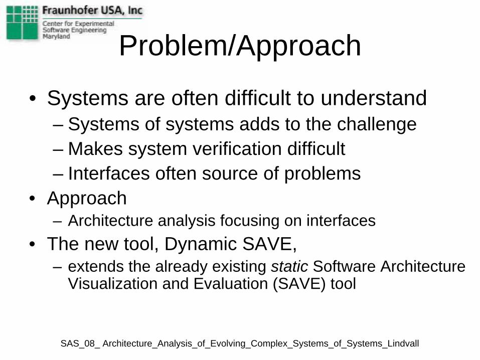
Problem/Approach
• Systems are often difficult to understand– Systems of systems adds to the challenge– Makes system verification difficult– Interfaces often source of problems
• Approach– Architecture analysis focusing on interfaces
• The new tool, Dynamic SAVE, – extends the already existing static Software Architecture
Visualization and Evaluation (SAVE) tool
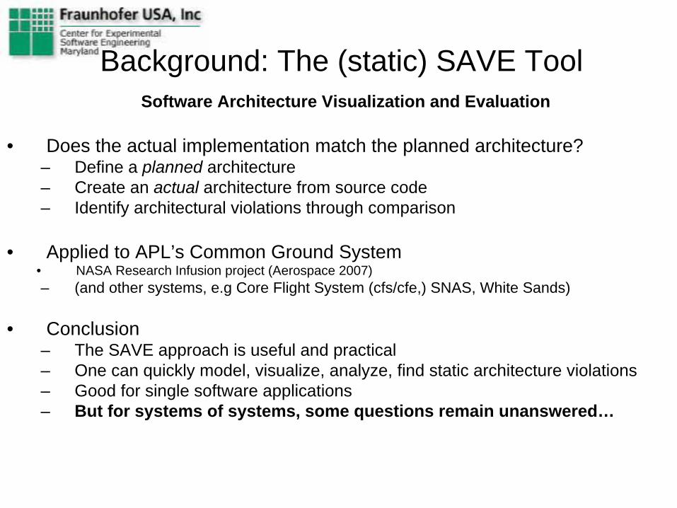
Background: The (static) SAVE Tool Software Architecture Visualization and Evaluation
• Does the actual implementation match the planned architecture?– Define a planned architecture– Create an actual architecture from source code– Identify architectural violations through comparison
• Applied to APL’s Common Ground System • NASA Research Infusion project (Aerospace 2007)– (and other systems, e.g Core Flight System (cfs/cfe,) SNAS, White Sands)
• Conclusion– The SAVE approach is useful and practical– One can quickly model, visualize, analyze, find static architecture violations– Good for single software applications– But for systems of systems, some questions remain unanswered…
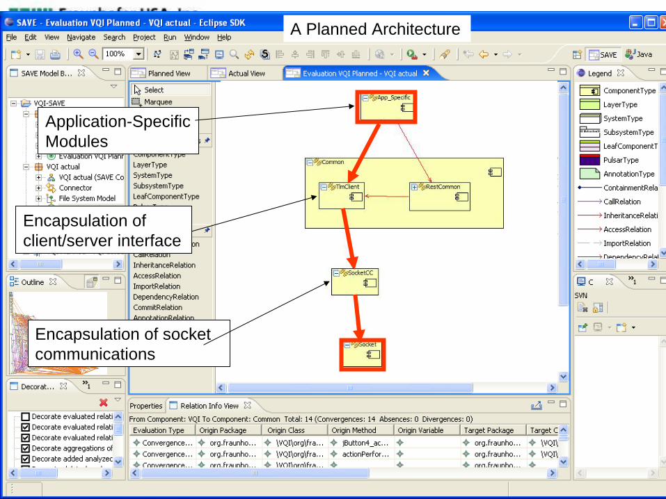
Application-Specific Modules
Encapsulation of client/server interface
Encapsulation of socket communications
A Planned Architecture
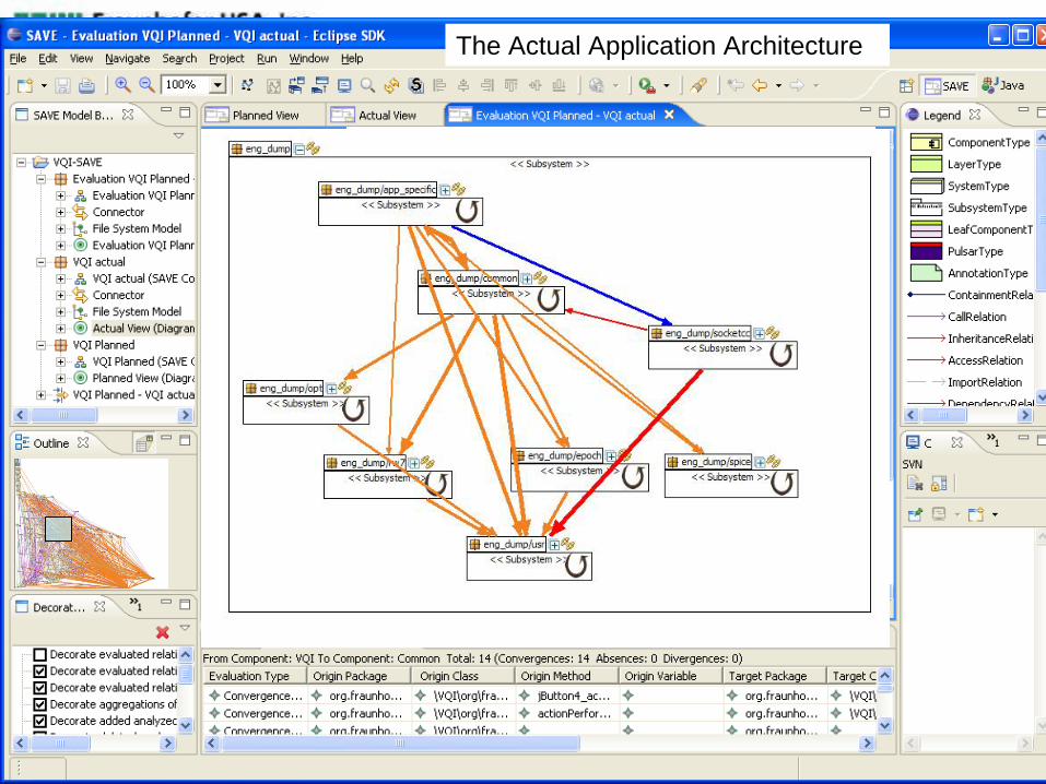
The Actual Application Architecture
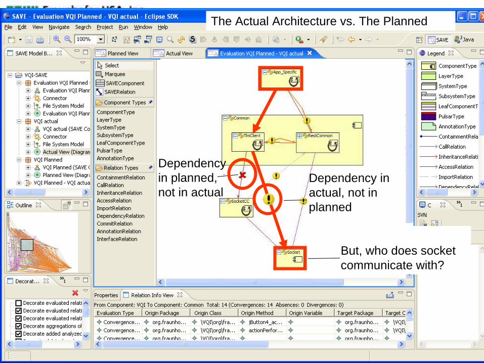
Dependency in actual, not in planned
Dependency in planned, not in actual
The Actual Architecture vs. The Planned
But, who does socket communicate with?
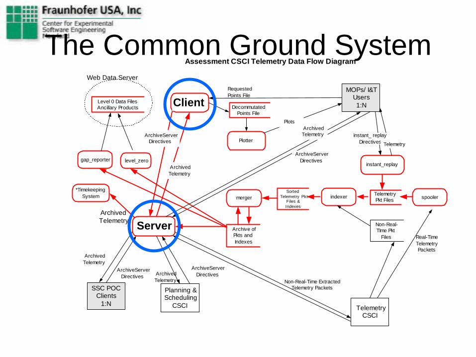
The Common Ground System
level_zero
indexer
archive_server
Planning &Scheduling
CSCI
SSC POCClients
1:N
ArchivedTelemetry
TelemetryCSCI
spooler
Real-TimeTelemetryPackets
Plotter
eng_dump
Assessment CSCI Telemetry Data Flow Diagram
MOPs/ I&TUsers1:N
ArchivedTelemetry
Level 0 Data FilesAncillary Products
ArchiveServerDirectives
DecommutatedPoints File
Non-Real-TIme Pkt
Files
Non-Real-Time ExtractedTelemetry Packets
Archive ofPkts andIndexes
ArchiveServerDirectives
TelemetryPkt Files
RequestedPoints File
ArchiveServerDirectivesArchived
Telemetry
*Timekeeping System expanded separately
Web Data Server
SortedTelemetry Pkt
Files &Indexes
merger*Timekeeping
System
ArchivedTelemetry
PlotsArchivedTelemetry
ArchiveServerDirectives
LHerrera 08/03
instant_replay
instant_ replayDirectives Telemetry
gap_reporter
Server
Client

Dyn-SAVE Vision
Telemetry Server
Telemetry Client
Specify PlannedBehavior
Form ActualBehavior
Specify Level of AbstractionFor analysis
Capture DynamicInformation
Compare Planned and ActualBehavior
• Who does socket communicate with?• Is communication according to specification?• Check Sequences, Parameters, Values, Timing

Dyn-SAVE Capabilities (Vision)
Telemetry Server
Telemetry Client
Form ActualBehavior
Specify Level of AbstractionFor analysis
Compare Planned and ActualBehavior
What components in the client are responsible for unspecified communication?
Reuse PlannedBehavior paintCompoonent

The Current Work On Dynamic SAVE
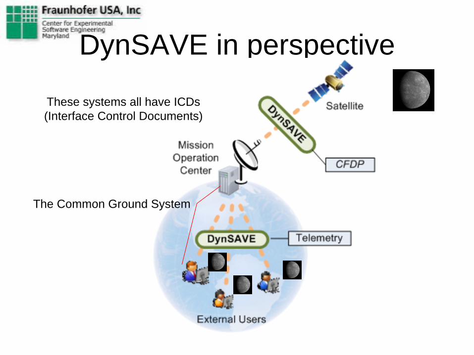
DynSAVE in perspective
12
The Common Ground System
These systems all have ICDs(Interface Control Documents)

Focus on: Interface Control Documents
– NASA systems often developed by different teams– Interface Control Documents (ICD) is key, but
• ICDs often interpreted differently because• ICDs implicit, lack important details etc.
– Cause subtle critical deviations from specified behavior • Deviations difficult to detect• Emerging behavior difficult to predict
– Can result in severe problems, e.g. lost data, performance– Need to
• Detect deviations before deployment• (Specify expected and actual behavior before creating ICD!)

Research Questions
• Sequence diagrams– Can we use sequence diagrams to model,
abstract, and detect such deviations? – Can sequence diagrams express what we
need?• Iterative modeling
– Can we start with abstract models, add details as necessary?
Approach
• Collect concrete examples from APL– Model planned behavior
• Use specification from ICD – Capture actual traces
• Use Archive_Server and Eng_Dump• Generate Client scenarios, observe how Server
responds
• Identify common patterns

Planned sequence diagram
The “simplest” diagram that describes the planned communication behavior described in the ICD
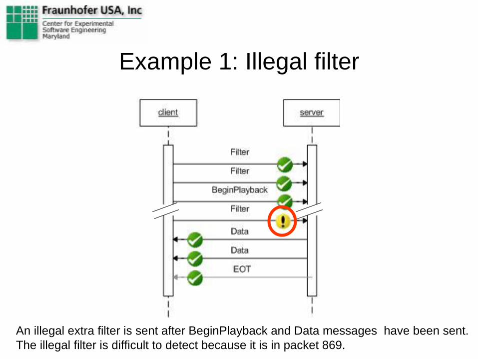
An illegal extra filter is sent after BeginPlayback and Data messages have been sent. The illegal filter is difficult to detect because it is in packet 869.
Example 1: Illegal filter
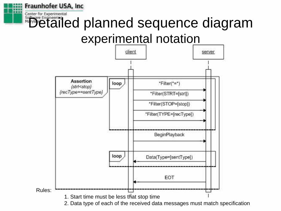
Rules: 1. Start time must be less that stop time2. Data type of each of the received data messages must match specification
Detailed planned sequence diagram experimental notation

Example 2: Illegal Type specification
STF ordered – STP received.
=STF)
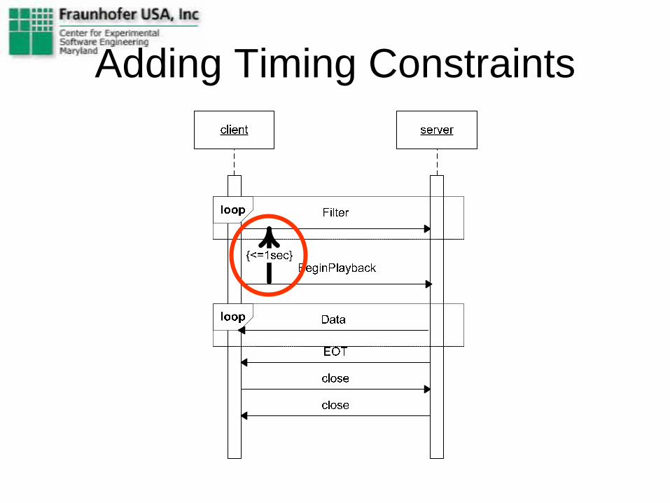
Adding Timing Constraints

Checking for Timing Problems
client server
Filter
BeginPlayback
Data
Data
Data
EOT
0s
1.85s
0.35s
0.1s
Data
0.1s
0.1s
0.1s
04-15-2008 dynSAVE 22
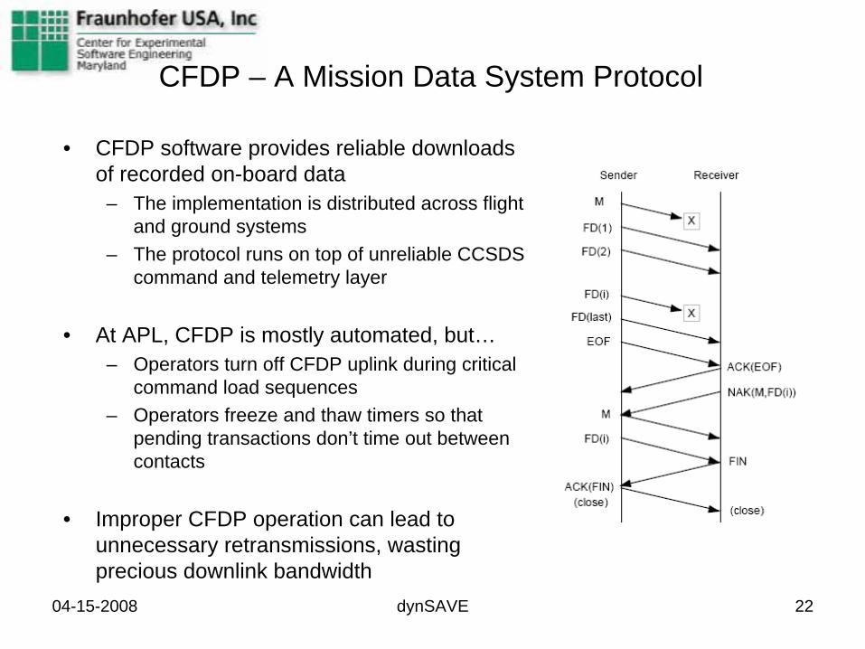
CFDP – A Mission Data System Protocol
• CFDP software provides reliable downloads of recorded on-board data
– The implementation is distributed across flight and ground systems
– The protocol runs on top of unreliable CCSDS command and telemetry layer
• At APL, CFDP is mostly automated, but…– Operators turn off CFDP uplink during critical
command load sequences– Operators freeze and thaw timers so that
pending transactions don’t time out between contacts
• Improper CFDP operation can lead to unnecessary retransmissions, wasting precious downlink bandwidth
04-15-2008 dynSAVE 23
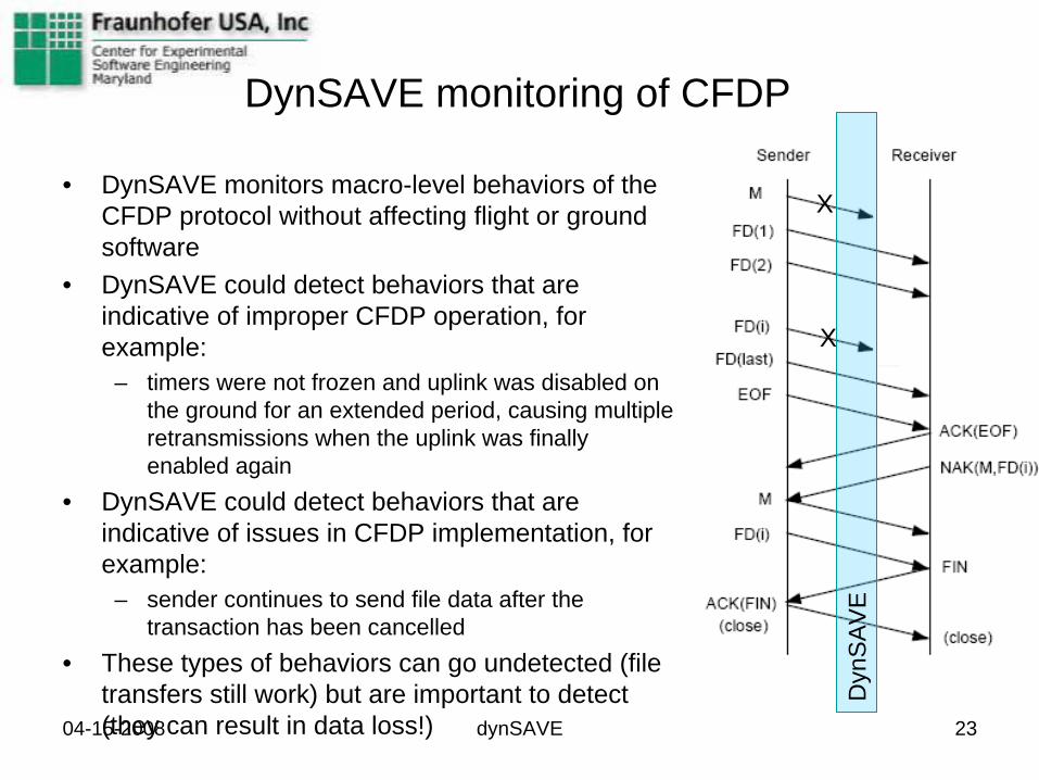
DynSAVE monitoring of CFDP
• DynSAVE monitors macro-level behaviors of the CFDP protocol without affecting flight or ground software
• DynSAVE could detect behaviors that are indicative of improper CFDP operation, for example:
– timers were not frozen and uplink was disabled on the ground for an extended period, causing multiple retransmissions when the uplink was finally enabled again
• DynSAVE could detect behaviors that are indicative of issues in CFDP implementation, for example:
– sender continues to send file data after the transaction has been cancelled
• These types of behaviors can go undetected (file transfers still work) but are important to detect (they can result in data loss!)
Dyn
SA
VE
X
X

Planned CFDP Sequence
Rules: 1.Check that received FD are not NAKed *2.Check for duplicate FDs *3.Check that we have all FDs upon FIN *4.Check that identical NAKs are not sent back-to-back unless timer went off

FileData: 482548-483544FileData: 483545-484541FileData: 484542-485538FileData: 485539-486535FileData: 486536-487532FileData: 487533-488529FileData: 488530-489526FileData: 489527-490523FileData: 491521-492517FileData: 492518-493514FileData: 493515-494511FileData: 494512-495508FileData: 495509-496505FileData: 498500-499496FileData: 499497-499999EOF: Condition Code=No ErrorACK(EOF): Condition Code=No ErrorNAK: 19940-20937;27916-28913;36889-37886;56829- 59820;72781-73778;76769-77766;82751-85742;101694- 102691;111664-112661;115652-116649;121634- 122631;130607-131604;139580-140577;146559- 147556;153538-154535;155532-156529;170487- 171484;197406-198403;203388-204385;220337-498500

Actual CFPD Sequence Annotated, Collapsed
Needed FDs: 502Send FDs: 840Potential Waste: ~70%? – Further analysis needed.

Zoom in on CFDP sequence
Rule 2 Violation: duplicate FD!

Life Cycle Support
SystemArchitecture
Use DynSAVE toSpecify and Test Communication
Add to ICD
Sub-SystemDevelopment
Use DynSAVE toDevelop and Test
based on ICD
SystemIntegration and Test
Use DynSAVE totest based
on ICD
Initial use of Dyn SAVE

Create System ArchitectureNo Server, No Client ExistUse DynSAVE to• Specify Planned communication
– Sequences– Parameters, Values– Timing constrains
• Create Tests– Correct, Incorrect behavior
• Specific incorrectness• Automatically generate defects
• Ensure that communication protocol can handle all tests
• Add Diagram, Specification, Tests to ICD
• “Generate” information for ICD
Client Server
Communication

Sub-System Development
No Client (or Server) ExistServer is built to ICDUse DynSAVE to• Import Planned spec from ICD• Use Tests from ICD, create new
– Correct and Incorrect behavior• Ensure that Server can handle all tests• Future research: Generate Mockup
Clients (exe) for test– Remotely controlled Mockup
• Turn on/off certain Mockup behavior
– Run simultaneously on several machines
Client Test Cases/Mockup Clients
DevelopedServer

Status
• Dyn-SAVE works for telemetry protocol• Currently adding functionality to evaluate
CFDP protocols• Applying Dyn-SAVE to APL’s systems• We’d like to apply to other systems

Summary
• Analyze, Visualize, and Evaluate – structure and behavior using – static and dynamic information– individual systems as well as systems of systems
• Next steps:– Refine software tool support– Use approach to review, improve ICD
• E.g. add planned sequence diagrams, rules to ICD– Apply to other systems to get feedback,
understand needs

SAS_08_ Architecture_Analysis_of_Evolving_Complex_Systems_of_Systems_Lindvall
Architecture Analysis of Evolving Complex Systems of Systems
Executive Status Report Software Assurance Symposium
2008
Principal Investigator (PI): Dr. Mikael Lindvall, FC-MDNASA POC: Sally Godfrey, GSFC
Team members: Chris Ackermann, Dr. Arnab Ray, Lyly Yonkwa, Dharma Ganesan (FC-MD)
William C. Stratton, Deane E. Sibol (APL) Fraunhofer Center for Experimental Software Engineering Maryland (FC-MD)
Fraunhofer Institute for Experimental Software Engineering (IESE)Johns Hopkins University Applied Physics Laboratory Space Department Ground Applications Group (APL)
SAS_08_ Architecture_Analysis_of_Evolving_Complex_Systems_of_Systems_Lindvall
Problem/Approach
• Systems are often difficult to understand– Systems of systems adds to the challenge– Makes system verification difficult– Interfaces often source of problems
• Approach– Architecture analysis focusing on interfaces
• The new tool, Dynamic SAVE, – extends the already existing static Software Architecture
Visualization and Evaluation (SAVE) tool

Dyn-SAVE Vision
Telemetry Server
Telemetry Client
Specify PlannedBehavior
Form ActualBehavior
Specify Level of AbstractionFor analysis
Capture DynamicInformation
Compare Planned and ActualBehavior
• Who does socket communicate with?• Is communication according to specification?• Check Sequences, Parameters, Values, Timing
SAS_08_ Architecture_Analysis_of_Evolving_Complex_Systems_of_Systems_Lindvall

Relevance to NASA– NASA systems often developed by different teams– Interface Control Documents (ICD) is key, but
• ICDs often interpreted differently because• ICDs implicit, lack important details etc.
– Cause subtle critical deviations from specified behavior • Deviations difficult to detect• Emerging behavior difficult to predict
– Can result in severe problems, e.g. lost data, performance– Need to
• Detect deviations before deployment• (Specify expected and actual behavior before creating ICD!)
SAS_08_ Architecture_Analysis_of_Evolving_Complex_Systems_of_Systems_Lindvall

DynSAVE in perspective
5
APL’s Common Ground System
These systems are based on ICDs(Interface Control Documents)
SAS_08_ Architecture_Analysis_of_Evolving_Complex_Systems_of_Systems_Lindvall

SAS_08_ Architecture_Analysis_of_Evolving_Complex_Systems_of_Systems_Lindvall
Current capabilities• Applied to APL’s Telemetry protocol
– See example below• Currently Capabilities allows us to
– Model planned behavior (based on ICD)• Sequences, Parameters, Values, Timing
– Capture and parse actual communication– Visualize actual behavior– Compare planned behavior to actual– Automatically detect and visualize deviations
• Already detected some surprising deviations!

Abstract planned diagram for Telemetry protocol
The “simplest” diagram that describes the planned communication behavior described in the ICD.
Enhance in iterative fashion.SAS_08_ Architecture_Analysis_of_Evolving_Complex_Systems_of_Systems_Lindvall

Detailed planned & actual
=STF)
Illegal FilterSpecificationSTF ordered –STP received
SAS_08_ Architecture_Analysis_of_Evolving_Complex_Systems_of_Systems_Lindvall
More examples and details in technical presentation!
SAS_08_ Architecture_Analysis_of_Evolving_Complex_Systems_of_Systems_Lindvall
Planned capabilitiesBeing able to• Model Planned behavior of
– Ground system software– Flight software– Communication between Ground and Flight
• e.g. CFDP
• Visualize actual behavior• Compare planned and Actual behavior• Automatically detect and visualize deviations
SAS_08_ Architecture_Analysis_of_Evolving_Complex_Systems_of_Systems_Lindvall
Technical challenges• Difficult to use existing case tools to create
planned sequence diagrams, e.g.– Most only support basic diagrams– Export formats often are not correct, usable
• Overcoming the problem– Provide importers for case tool– Provide our own sequence diagram editors

SAS_08_ Architecture_Analysis_of_Evolving_Complex_Systems_of_Systems_Lindvall
Summary
• Analyze, Visualize, and Evaluate – structure and behavior using – static and dynamic information– individual systems as well as systems of systems
• Next steps:– Refine software tool support– Apply to other systems– Apply earlier in system life cycle