Grokking Tech Talk 15: Architectural decisions @ Parcel Perform

1
ARCHITECTURAL REVIEW BOARD STAFF REPORT
Project #/Name ARB-2020-34: Valvoline Initial Site Plan
Review Type Initial Site Plan/Preliminary Review of Architectural Design
Parcel Identification 04500-00-00-111C0
Location East of 29 North, west of Gander Drive between Atlantic Union Bank and Goodwill
Zoned Highway Commercial (HC), Entrance Corridor (EC)
Owner/Applicant First Gold Leaf Land Trust / CESO (Kelly Schwieterman)
Magisterial District Rio
Proposal To construct a 2,080-sf oil change facility with associated site improvements on approximately .52 acres.
Context The subject property is accessed by an internal road, Gander Drive, and is located within the Northtown Center
development. Route 29 is largely characterized by commercial development with nearby developments including
Rivanna Plaza across Route 29 to the west, Lowe’s and Rio Hill Shopping Center to the southwest, Harbor Freight
and Goodwill in the former Gander Mountain store to the south, and another phase of the Northtown Center to the
southeast.
Visibility The north, south (sides), and west (front) elevations are expected to be visible from the Entrance Corridor.
ARB Meeting Date April 20, 2020
Staff Contact Khris Taggart
PROJECT HISTORY
The ARB reviewed ARB-2013-183, a proposal to construct a one-story, 2,400 s.f. Sonic restaurant with associated parking, outdoor seating and drive-
thru/drive-in food service for this site.

2
Fig 1: Google Image (left showing project area along the Entrance Corridor and County GIS map (right) highlighting subject property.
ANALYSIS
Gray highlight = means the guideline can’t be reviewed at initial site plan stage, but recommendations can be provided for final
Yellow highlight = means the guideline can only be reviewed for location/configuration at the initial plan stage
Regular text = means the guideline can be reviewed at initial plan stage, can be made a condition of initial plan approval, and can be the basis for denial
REF GUIDELINE ISSUE RECOMMENDATION
Purpose, Compatibility with significant historic sites and the character of the Entrance Corridor; Structure design
1 The goal of the regulation of the design of development
within the designated Entrance Corridors is to ensure that
new development within the corridors reflects the
traditional architecture of the area. Therefore, it is the
purpose of ARB review and of these Guidelines, that
proposed development within the designated Entrance
Corridors reflect elements of design characteristic of the
significant historical landmarks, buildings, and structures
of the Charlottesville and Albemarle area, and to promote
orderly and attractive development within these corridors.
Applicants should note that replication of historic structures
is neither required nor desired.
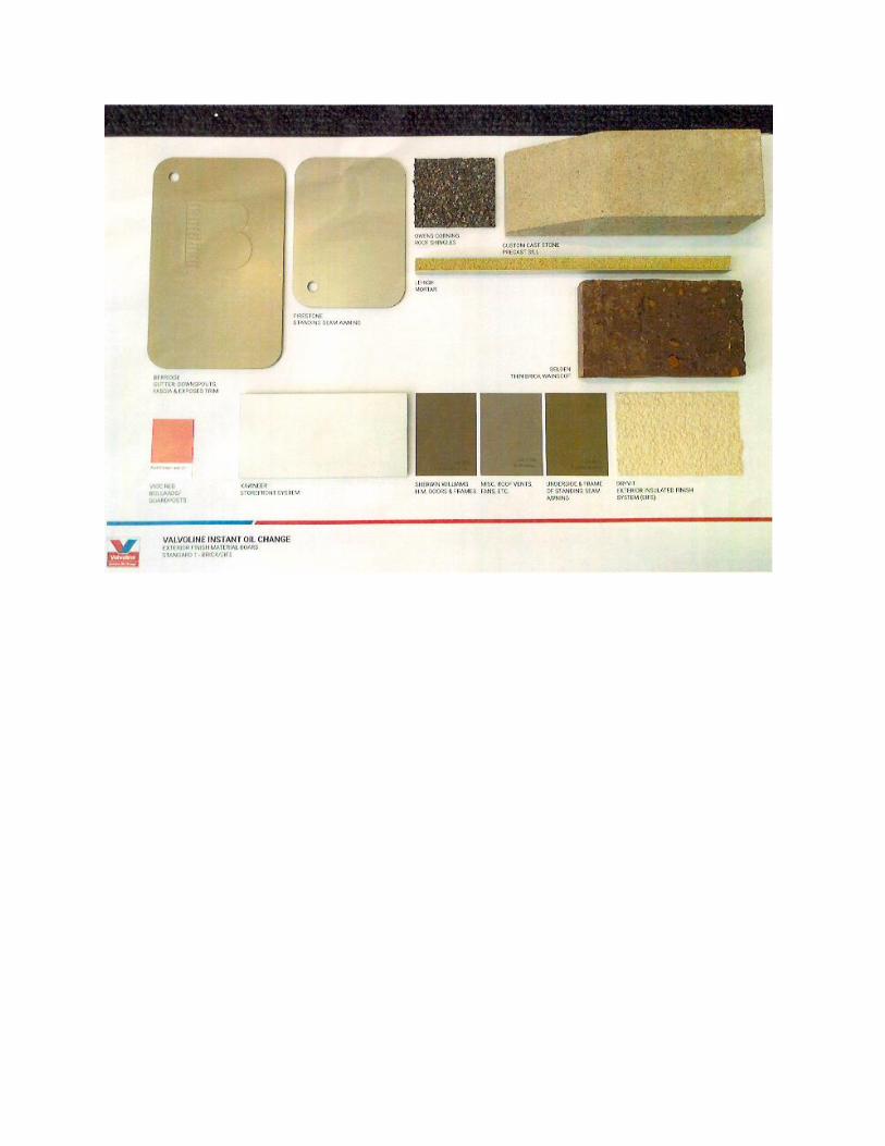
The building’s simple form, roof shape, and
tower element and awnings emphasizing the
entrance are features found in local historic
buildings; however, the use of EIFS as the
primary building material is not reflective of
traditional architecture of the area. Revising
the mix of wall materials, making brick the
primary material and using EIFS only as a
minor material for detailing, would be more
appropriate. Incorporating a second color of
brick may help to further integrate the
building into the surrounding context of
Revise the design to
make brick the primary
wall material. Limit EIFS
to a minor material for
detailing.
3
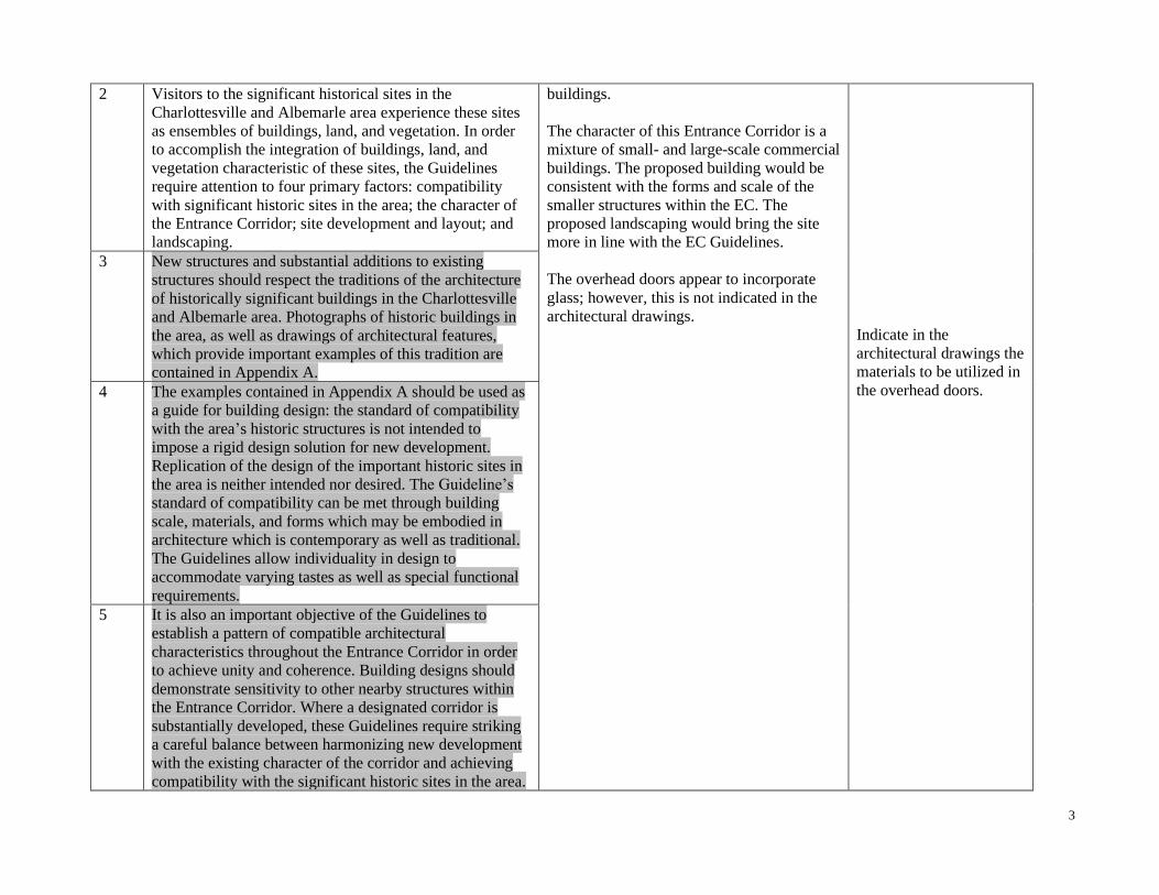
2 Visitors to the significant historical sites in the
Charlottesville and Albemarle area experience these sites
as ensembles of buildings, land, and vegetation. In order
to accomplish the integration of buildings, land, and
vegetation characteristic of these sites, the Guidelines
require attention to four primary factors: compatibility
with significant historic sites in the area; the character of
the Entrance Corridor; site development and layout; and
landscaping.
buildings.
The character of this Entrance Corridor is a
mixture of small- and large-scale commercial
buildings. The proposed building would be
consistent with the forms and scale of the
smaller structures within the EC. The
proposed landscaping would bring the site
more in line with the EC Guidelines.
The overhead doors appear to incorporate
glass; however, this is not indicated in the
architectural drawings.
Indicate in the
architectural drawings the
materials to be utilized in
the overhead doors.
3 New structures and substantial additions to existing
structures should respect the traditions of the architecture
of historically significant buildings in the Charlottesville
and Albemarle area. Photographs of historic buildings in
the area, as well as drawings of architectural features,
which provide important examples of this tradition are
contained in Appendix A.
4 The examples contained in Appendix A should be used as
a guide for building design: the standard of compatibility
with the area’s historic structures is not intended to
impose a rigid design solution for new development.
Replication of the design of the important historic sites in
the area is neither intended nor desired. The Guideline’s
standard of compatibility can be met through building
scale, materials, and forms which may be embodied in
architecture which is contemporary as well as traditional.
The Guidelines allow individuality in design to
accommodate varying tastes as well as special functional
requirements.
5 It is also an important objective of the Guidelines to
establish a pattern of compatible architectural
characteristics throughout the Entrance Corridor in order
to achieve unity and coherence. Building designs should
demonstrate sensitivity to other nearby structures within
the Entrance Corridor. Where a designated corridor is
substantially developed, these Guidelines require striking
a careful balance between harmonizing new development
with the existing character of the corridor and achieving
compatibility with the significant historic sites in the area.
4
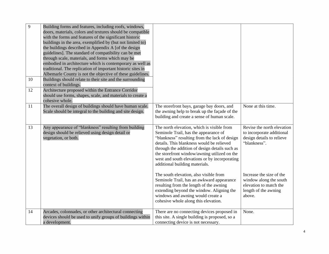
9 Building forms and features, including roofs, windows,
doors, materials, colors and textures should be compatible
with the forms and features of the significant historic
buildings in the area, exemplified by (but not limited to)
the buildings described in Appendix A [of the design
guidelines]. The standard of compatibility can be met
through scale, materials, and forms which may be
embodied in architecture which is contemporary as well as
traditional. The replication of important historic sites in
Albemarle County is not the objective of these guidelines.
10 Buildings should relate to their site and the surrounding
context of buildings.
12 Architecture proposed within the Entrance Corridor
should use forms, shapes, scale, and materials to create a
cohesive whole.
11 The overall design of buildings should have human scale.
Scale should be integral to the building and site design.
The storefront bays, garage bay doors, and
the awning help to break up the façade of the
building and create a sense of human scale.
None at this time.
13 Any appearance of “blankness” resulting from building
design should be relieved using design detail or
vegetation, or both.
The north elevation, which is visible from
Seminole Trail, has the appearance of
“blankness” resulting from the lack of design
details. This blankness would be relieved
through the addition of design details such as
the storefront window/awning utilized on the
west and south elevations or by incorporating
additional building materials.
The south elevation, also visible from
Seminole Trail, has an awkward appearance
resulting from the length of the awning
extending beyond the window. Aligning the
windows and awning would create a
cohesive whole along this elevation.
Revise the north elevation
to incorporate additional
design details to relieve
“blankness”.
Increase the size of the
window along the south
elevation to match the
length of the awning
above.
14 Arcades, colonnades, or other architectural connecting
devices should be used to unify groups of buildings within
a development.
There are no connecting devices proposed in
this site. A single building is proposed, so a
connecting device is not necessary.
None.

5
15 Trademark buildings and related features should be
modified to meet the requirements of the Guidelines.
This building appears to be a standardized
design with options for building materials.
Revise the EIFS to a
secondary building
material to better meet
the requirements of the
Guidelines.
16 Window glass in the Entrance Corridors should not be
highly tinted or highly reflective. Window glass in the
Entrance Corridors should meet the following criteria:
Visible light transmittance (VLT) shall not drop below
40%. Visible light reflectance (VLR) shall not exceed
30%. Specifications on the proposed window glass should
be submitted with the application for final review.
Specifications on the proposed window glass
and samples of tinted window glass have not
been submitted at this time.
Provide specifications on
the proposed window
glass. Provide samples, if
tinted window glass is
proposed.
Accessory structures and equipment
17 Accessory structures and equipment should be integrated
into the overall plan of development and shall, to the
extent possible, be compatible with the building designs
used on the site.
There are no accessory structures proposed.
The proposed equipment, located behind the
building, is not expected to be visible from
the Entrance Corridor.
None.
18 The following should be located to eliminate visibility from
the Entrance Corridor street. If, after appropriate siting,
these features will still have a negative visual impact on the
Entrance Corridor street, screening should be provided to
eliminate visibility. a. Loading areas, b. Service areas, c.
Refuse areas, d. Storage areas, e. Mechanical equipment,
f. Above-ground utilities, and g. Chain link fence, barbed
wire, razor wire, and similar security fencing devices.
The dumpster is screened from view of the
EC street by landscaping and a CMU wall
clad in brick/EIFS veneer matching the
building.
The proposed ground mounted equipment,
located behind the building, is not expected
to be visible from the Entrance Corridor.
There are roof vents proposed on the north,
east and south sides of the main roof and the
east side of the tower roof. In the current
locations shown, 4 out of the 12 vents are
expected to be partially visible. However, the
architectural plans include a note stating,
“verify quantity and locations” of the
proposed equipment. The equipment,
including the visible portions, is proposed to
be painted SW 7046 Anonymous to match
the roof. The current locations shown and the
None.
None.
None.

6
color proposed sufficiently mitigates the
visibility of the proposed equipment. Note
that alternate locations with greater visibility
will not be approved.
The gas meter located near the northeast
corner of the building may be visible from
the EC. Relocating it to the rear elevation
would eliminate visibility from the EC.
Revise the building
elevations to show the
gas meter along the rear
elevation.
19 Screening devices should be compatible with the design of
the buildings and surrounding natural vegetation and may
consist of: a. Walls, b. Plantings, and c. Fencing.
The dumpster enclosure is clad in brick/EIFS
veneer matching the building.
None.
21 The following note should be added to the site plan and the
architectural plan: “Visibility of all mechanical equipment
from the Entrance Corridor shall be eliminated.”
The note is not present on the site or
architectural plan.
Add the standard
mechanical equipment
note to the site and
architectural plans.
Lighting
22 Light should be contained on the site and not spill over
onto adjacent properties or streets;
The lighting does not exceed .5 foot-candles
over any public roadways or adjacent
properties.
None.
23 Light should be shielded, recessed or flush-mounted to
eliminate glare. All fixtures with lamps emitting 3000
lumens or more must be full cutoff fixtures.
The proposed lighting is flush mounted. The
proposed lamps emitting 3000 lumens or
more are full cutoff.
None.
24 Light levels exceeding 30 foot-candles are not appropriate
for display lots in the Entrance Corridors. Lower light
levels will apply to most other uses in the Entrance
Corridors.
The maximum proposed illumination at the
ground is 6.8 fc, which is expected to have
an appropriate appearance.
None.
25 Light should have the appearance of white light with a
warm soft glow; however, a consistent appearance
throughout a site or development is required.
Consequently, if existing lamps that emit non-white light
are to remain, new lamps may be required to match them.
The proposed fixtures do not have a
consistent color temperature. The pole-
mounted fixtures have a color temperature
approximating white daylight (5k) while the
wall-mounted fixtures have a color
temperature of soft, warm white (3k).
Revise the pole-mounted
fixtures to soft, warm
white (3k).
26 Dark brown, dark bronze, or black are appropriate colors
for free-standing pole mounted light fixtures in the
Entrance Corridors.
The wall and pole-mounted fixtures are
proposed with a black finish.
None.
7
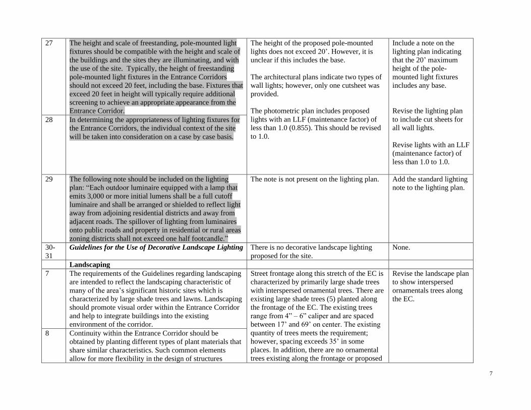
27 The height and scale of freestanding, pole-mounted light
fixtures should be compatible with the height and scale of
the buildings and the sites they are illuminating, and with
the use of the site. Typically, the height of freestanding
pole-mounted light fixtures in the Entrance Corridors
should not exceed 20 feet, including the base. Fixtures that
exceed 20 feet in height will typically require additional
screening to achieve an appropriate appearance from the
Entrance Corridor.
The height of the proposed pole-mounted
lights does not exceed 20’. However, it is
unclear if this includes the base.
The architectural plans indicate two types of
wall lights; however, only one cutsheet was
provided.
The photometric plan includes proposed
lights with an LLF (maintenance factor) of
less than 1.0 (0.855). This should be revised
to 1.0.
Include a note on the
lighting plan indicating
that the 20’ maximum
height of the pole-
mounted light fixtures
includes any base.
Revise the lighting plan
to include cut sheets for
all wall lights.
Revise lights with an LLF
(maintenance factor) of
less than 1.0 to 1.0.
28 In determining the appropriateness of lighting fixtures for
the Entrance Corridors, the individual context of the site
will be taken into consideration on a case by case basis.
29 The following note should be included on the lighting
plan: “Each outdoor luminaire equipped with a lamp that
emits 3,000 or more initial lumens shall be a full cutoff
luminaire and shall be arranged or shielded to reflect light
away from adjoining residential districts and away from
adjacent roads. The spillover of lighting from luminaires
onto public roads and property in residential or rural areas
zoning districts shall not exceed one half footcandle.”
The note is not present on the lighting plan. Add the standard lighting
note to the lighting plan.
30-
31
Guidelines for the Use of Decorative Landscape Lighting There is no decorative landscape lighting
proposed for the site.
None.
Landscaping
7 The requirements of the Guidelines regarding landscaping
are intended to reflect the landscaping characteristic of
many of the area’s significant historic sites which is
characterized by large shade trees and lawns. Landscaping
should promote visual order within the Entrance Corridor
and help to integrate buildings into the existing
environment of the corridor.
Street frontage along this stretch of the EC is
characterized by primarily large shade trees
with interspersed ornamental trees. There are
existing large shade trees (5) planted along
the frontage of the EC. The existing trees
range from 4” – 6” caliper and are spaced
between 17’ and 69’ on center. The existing
quantity of trees meets the requirement;
however, spacing exceeds 35’ in some
places. In addition, there are no ornamental
trees existing along the frontage or proposed
Revise the landscape plan
to show interspersed
ornamentals trees along
the EC.
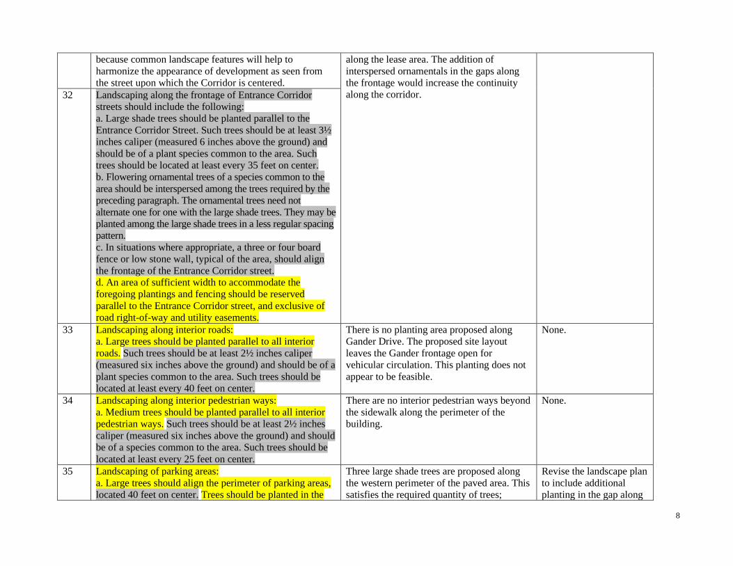
8 Continuity within the Entrance Corridor should be
obtained by planting different types of plant materials that
share similar characteristics. Such common elements
allow for more flexibility in the design of structures
8
because common landscape features will help to
harmonize the appearance of development as seen from
the street upon which the Corridor is centered.
along the lease area. The addition of
interspersed ornamentals in the gaps along
the frontage would increase the continuity
along the corridor.
32 Landscaping along the frontage of Entrance Corridor
streets should include the following:
a. Large shade trees should be planted parallel to the
Entrance Corridor Street. Such trees should be at least 3½
inches caliper (measured 6 inches above the ground) and
should be of a plant species common to the area. Such
trees should be located at least every 35 feet on center.
b. Flowering ornamental trees of a species common to the
area should be interspersed among the trees required by the
preceding paragraph. The ornamental trees need not
alternate one for one with the large shade trees. They may be
planted among the large shade trees in a less regular spacing
pattern.
c. In situations where appropriate, a three or four board
fence or low stone wall, typical of the area, should align
the frontage of the Entrance Corridor street.
d. An area of sufficient width to accommodate the
foregoing plantings and fencing should be reserved
parallel to the Entrance Corridor street, and exclusive of
road right-of-way and utility easements.
33 Landscaping along interior roads:
a. Large trees should be planted parallel to all interior
roads. Such trees should be at least 2½ inches caliper
(measured six inches above the ground) and should be of a
plant species common to the area. Such trees should be
located at least every 40 feet on center.
There is no planting area proposed along
Gander Drive. The proposed site layout
leaves the Gander frontage open for
vehicular circulation. This planting does not
appear to be feasible.
None.
34 Landscaping along interior pedestrian ways:
a. Medium trees should be planted parallel to all interior
pedestrian ways. Such trees should be at least 2½ inches
caliper (measured six inches above the ground) and should
be of a species common to the area. Such trees should be
located at least every 25 feet on center.
There are no interior pedestrian ways beyond
the sidewalk along the perimeter of the
building.
None.
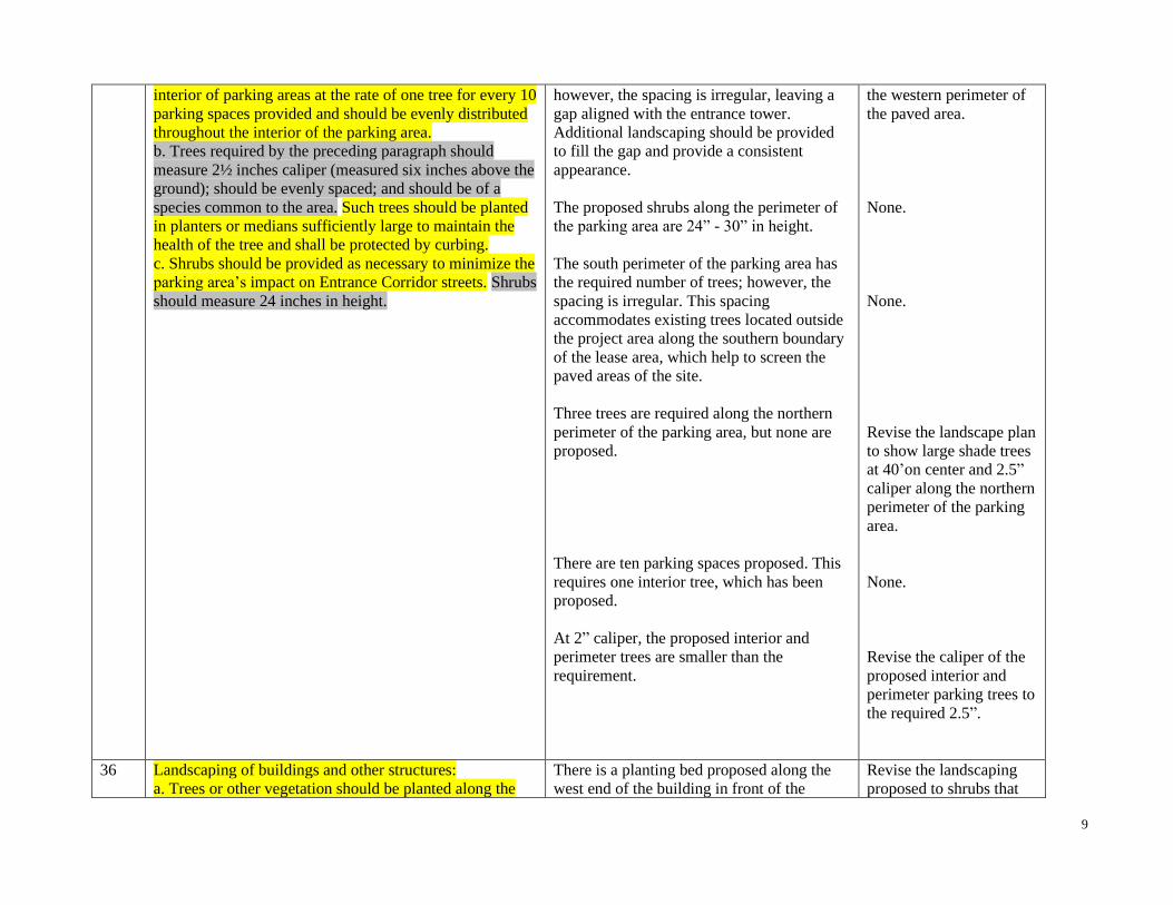
35 Landscaping of parking areas:
a. Large trees should align the perimeter of parking areas,
located 40 feet on center. Trees should be planted in the
Three large shade trees are proposed along
the western perimeter of the paved area. This
satisfies the required quantity of trees;
Revise the landscape plan
to include additional
planting in the gap along
9
interior of parking areas at the rate of one tree for every 10
parking spaces provided and should be evenly distributed
throughout the interior of the parking area.
b. Trees required by the preceding paragraph should
measure 2½ inches caliper (measured six inches above the
ground); should be evenly spaced; and should be of a
species common to the area. Such trees should be planted
in planters or medians sufficiently large to maintain the
health of the tree and shall be protected by curbing.
c. Shrubs should be provided as necessary to minimize the
parking area’s impact on Entrance Corridor streets. Shrubs
should measure 24 inches in height.
however, the spacing is irregular, leaving a
gap aligned with the entrance tower.
Additional landscaping should be provided
to fill the gap and provide a consistent
appearance.
The proposed shrubs along the perimeter of
the parking area are 24” - 30” in height.
The south perimeter of the parking area has
the required number of trees; however, the
spacing is irregular. This spacing
accommodates existing trees located outside
the project area along the southern boundary
of the lease area, which help to screen the
paved areas of the site.
Three trees are required along the northern
perimeter of the parking area, but none are
proposed.
There are ten parking spaces proposed. This
requires one interior tree, which has been
proposed.
At 2” caliper, the proposed interior and
perimeter trees are smaller than the
requirement.
the western perimeter of
the paved area.
None.
None.
Revise the landscape plan
to show large shade trees
at 40’on center and 2.5”
caliper along the northern
perimeter of the parking
area.
None.
Revise the caliper of the
proposed interior and
perimeter parking trees to
the required 2.5”.
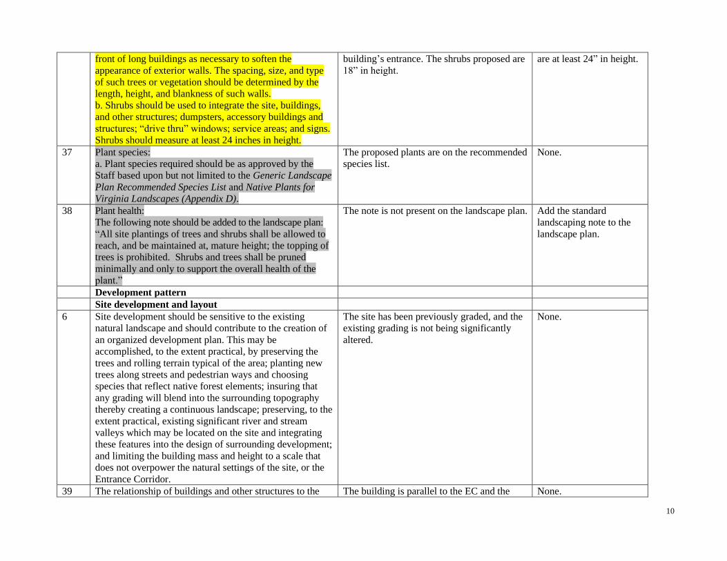
36 Landscaping of buildings and other structures:
a. Trees or other vegetation should be planted along the
There is a planting bed proposed along the
west end of the building in front of the
Revise the landscaping
proposed to shrubs that
10
front of long buildings as necessary to soften the
appearance of exterior walls. The spacing, size, and type
of such trees or vegetation should be determined by the
length, height, and blankness of such walls.
b. Shrubs should be used to integrate the site, buildings,
and other structures; dumpsters, accessory buildings and
structures; “drive thru” windows; service areas; and signs.
Shrubs should measure at least 24 inches in height.
building’s entrance. The shrubs proposed are
18” in height.
are at least 24” in height.
37 Plant species:
a. Plant species required should be as approved by the
Staff based upon but not limited to the Generic Landscape
Plan Recommended Species List and Native Plants for
Virginia Landscapes (Appendix D).
The proposed plants are on the recommended
species list.
None.
38 Plant health:
The following note should be added to the landscape plan:
“All site plantings of trees and shrubs shall be allowed to
reach, and be maintained at, mature height; the topping of
trees is prohibited. Shrubs and trees shall be pruned
minimally and only to support the overall health of the
plant.”
The note is not present on the landscape plan. Add the standard
landscaping note to the
landscape plan.
Development pattern
Site development and layout
6 Site development should be sensitive to the existing
natural landscape and should contribute to the creation of
an organized development plan. This may be
accomplished, to the extent practical, by preserving the
trees and rolling terrain typical of the area; planting new
trees along streets and pedestrian ways and choosing
species that reflect native forest elements; insuring that
any grading will blend into the surrounding topography
thereby creating a continuous landscape; preserving, to the
extent practical, existing significant river and stream
valleys which may be located on the site and integrating
these features into the design of surrounding development;
and limiting the building mass and height to a scale that
does not overpower the natural settings of the site, or the
Entrance Corridor.
The site has been previously graded, and the
existing grading is not being significantly
altered.
None.
39 The relationship of buildings and other structures to the The building is parallel to the EC and the None.

11
Entrance Corridor street and to other development within
the corridor should be as follows:
a. An organized pattern of roads, service lanes, bike paths,
and pedestrian walks should guide the layout of the site.
b. In general, buildings fronting the Entrance Corridor
street should be parallel to the street. Building groupings
should be arranged to parallel the Entrance Corridor street.
c. Provisions should be made for connections to adjacent
pedestrian and vehicular circulation systems.
d. Open spaces should be tied into surrounding areas to
provide continuity within the Entrance Corridor.
e. If significant natural features exist on the site (including
creek valleys, steep slopes, significant trees or rock
outcroppings), to the extent practical, then such natural
features should be reflected in the site layout. If the
provisions of Section 32.5.2.n of the Albemarle County
Zoning Ordinance apply, then improvements required by
that section should be located so as to maximize the use of
existing features in screening such improvements from
Entrance Corridor streets.
f. The placement of structures on the site should respect
existing views and vistas on and around the site.
distance from the building to the EC and on-
site circulation patterns are similar to the
surrounding area.
An existing sidewalk runs along Seminole
Trail and is to remain.
The site has been previously graded. No
significant natural features remain.
Views are not expected to be negatively
impacted.
Site Grading
40 Site grading should maintain the basic relationship of the
site to surrounding conditions by limiting the use of
retaining walls and by shaping the terrain through the use of
smooth, rounded landforms that blend with the existing
terrain. Steep cut or fill sections are generally unacceptable.
Proposed contours on the grading plan shall be rounded with
a ten-foot minimum radius where they meet the adjacent
condition. Final grading should achieve a natural, rather than
engineered, appearance. Retaining walls 6 feet in height and
taller, when necessary, shall be terraced and planted to blend
with the landscape.
The existing site grading is not being
significantly altered.
None.
12
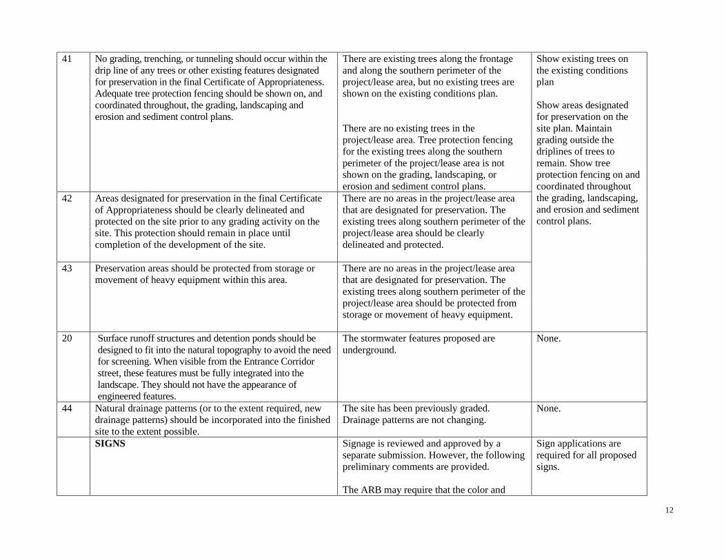
41 No grading, trenching, or tunneling should occur within the
drip line of any trees or other existing features designated
for preservation in the final Certificate of Appropriateness.
Adequate tree protection fencing should be shown on, and
coordinated throughout, the grading, landscaping and
erosion and sediment control plans.
There are existing trees along the frontage
and along the southern perimeter of the
project/lease area, but no existing trees are
shown on the existing conditions plan.
There are no existing trees in the
project/lease area. Tree protection fencing
for the existing trees along the southern
perimeter of the project/lease area is not
shown on the grading, landscaping, or
erosion and sediment control plans.
Show existing trees on
the existing conditions
plan
Show areas designated
for preservation on the
site plan. Maintain
grading outside the
driplines of trees to
remain. Show tree
protection fencing on and
coordinated throughout
the grading, landscaping,
and erosion and sediment
control plans.
42 Areas designated for preservation in the final Certificate
of Appropriateness should be clearly delineated and
protected on the site prior to any grading activity on the
site. This protection should remain in place until
completion of the development of the site.
There are no areas in the project/lease area
that are designated for preservation. The
existing trees along southern perimeter of the
project/lease area should be clearly
delineated and protected.
43 Preservation areas should be protected from storage or
movement of heavy equipment within this area.
There are no areas in the project/lease area
that are designated for preservation. The
existing trees along southern perimeter of the
project/lease area should be protected from
storage or movement of heavy equipment.
20 Surface runoff structures and detention ponds should be
designed to fit into the natural topography to avoid the need
for screening. When visible from the Entrance Corridor
street, these features must be fully integrated into the
landscape. They should not have the appearance of
engineered features.
The stormwater features proposed are
underground.
None.
44 Natural drainage patterns (or to the extent required, new
drainage patterns) should be incorporated into the finished
site to the extent possible.
The site has been previously graded.
Drainage patterns are not changing.
None.
SIGNS Signage is reviewed and approved by a
separate submission. However, the following
preliminary comments are provided.
The ARB may require that the color and
Sign applications are
required for all proposed
signs.

13
scale of standard templates for trademarks,
service marks, corporate logos, and graphics
be modified.
Cabinet style signs are shown on the west,
south and east elevations. This is not the
preferred sign type in the ECs. Note the
cabinet sign on the east elevation will not be
visible from the EC; therefore; that particular
sign does not require ARB review. If
illuminated, the background portion of the
cabinet style signs must be opaque.
The signs appear to propose four colors. The
use of three colors or fewer is appropriate for
signs in the Entrance Corridor.
The Pantone equivalents for the proposed
sign colors are not indicated in the
architectural drawings but similar signs use
Pantone red 485C. 485C is not approvable as
a primary sign color. Pantone 187C has been
approved as an acceptable substitute by the
ARB. On a case by case basis, 485C may be
acceptable as a secondary color.
Eliminate cabinet style
signs or limit them to
secondary signs. All
cabinet type signs must
have opaque
backgrounds.
Reduce the number of
colors used in the sign to
be no more than three
(including white).
Eliminate overly intense
colors from the sign
proposal.
SUMMARY OF RECOMMENDATIONS
Staff recommends the following as the primary points of discussion:
1. Landscaping along the EC and the perimeter of the parking area.
2. Proposed building materials.
3. Design of the north and south elevations.
4. The signage shown in the elevations.
Staff recommends that the ARB forward the following recommendations to the Agent for the Site Review Committee:

14
• Regarding requirements to satisfy the design guidelines as per § 18-30.6.4c(2), (3) and (5) and recommended conditions of initial plan approval:
None.
• Regarding recommendations on the plan as it relates to the guidelines:
None.
• Regarding conditions to be satisfied prior to issuance of a grading permit:
1. Maintain grading outside the driplines of trees to remain. Show tree protection fencing on, and coordinated throughout, the grading,
landscaping, and erosion and sediment control plans.
• Regarding the final site plan submittal:
A Certificate of Appropriateness is required prior to final site plan approval. The following items and all items on the ARB Final Site Plan
Checklist must be addressed:
1. Revise the design to make brick the primary wall material. Limit EIFS to a minor material for detailing.
2. Indicate in the architectural drawings the materials to be utilized in the overhead doors.
3. Revise the north elevation to incorporate additional design details to relieve “blankness”.
4. Increase the size of the window along the south elevation to match the length of the awning above.
5. Revise the EIFS to a secondary building material to better meet the requirements of the Guidelines.
6. Provide specifications on the proposed window glass. Provide samples, if tinted window glass is proposed.
7. Revise the building elevations to show the gas meter along the rear elevation.
8. Add the standard mechanical equipment note to the site and architectural plans.
9. Revise the pole-mounted fixtures to soft, warm white (3k).
10. Include a note on the lighting plan indicating that the 20’ maximum height of the pole-mounted light fixtures includes any base.
11. Revise the lighting plan to include cut sheets for all wall lights.
12. Revise lights with an LLF (maintenance factor) of less than 1.0 to 1.0.
13. Add the standard lighting note to the lighting plan.
14. Revise the landscape plan to show interspersed ornamentals trees along the EC.
15. Revise the landscape plan to include additional planting in the gap along the western perimeter of the paved area.
16. Revise the landscape plan to show large shade trees at 40’on center and 2.5” caliper along the northern perimeter of the parking area.
17. Revise the caliper of the proposed interior and perimeter parking trees to the required 2.5”.
18. Revise the landscaping proposed to shrubs that are at least 24” in height.
19. Add the standard landscaping note to the landscape plan.
20. Show existing trees on the existing conditions plan.
15
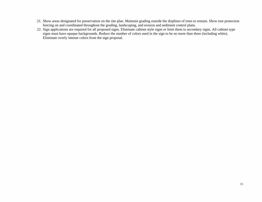
21. Show areas designated for preservation on the site plan. Maintain grading outside the driplines of trees to remain. Show tree protection
fencing on and coordinated throughout the grading, landscaping, and erosion and sediment control plans.
22. Sign applications are required for all proposed signs. Eliminate cabinet style signs or limit them to secondary signs. All cabinet type
signs must have opaque backgrounds. Reduce the number of colors used in the sign to be no more than three (including white).
Eliminate overly intense colors from the sign proposal.

16
TABLE A
This report is based on the following submittal items:
Sheet # Drawing Name Drawing Date/Revision Date
Site Plan
C1.0 Title 3/6/20
C2.0 Ex. Conditions and Demolition Plan 3/6/20
C3.0 Site Plan 3/6/20
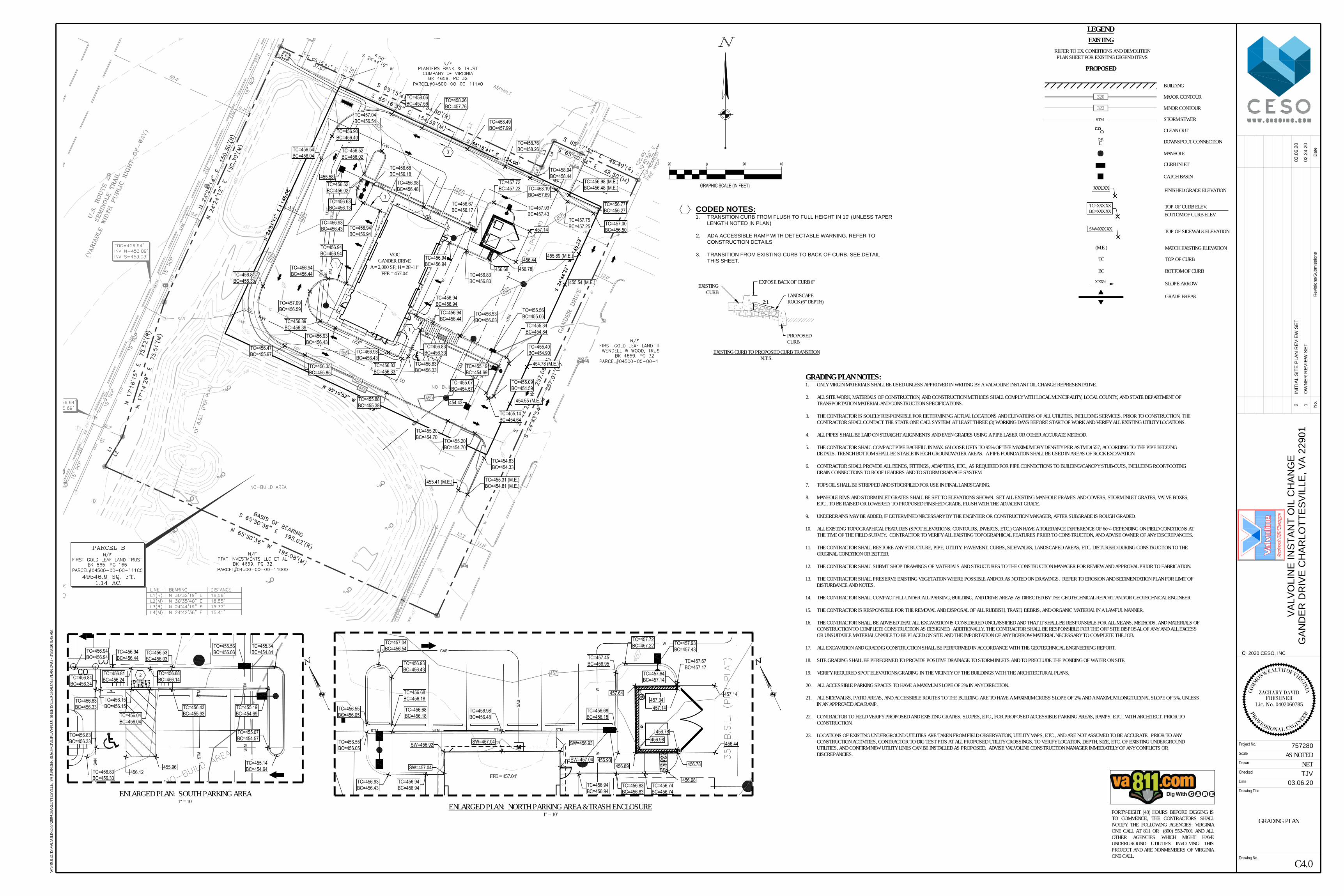
C4.0 Grading Plan 3/6/20
C5.0 Storm Drainage Plan 3/6/20
C6.0 Utility Plan 3/6/20
C7.0 Construction Details 3/6/20
C8.0 Photometric Plan 3/6/20
L1.0 Landscape Plan 3/6/20
L2.0 Irrigation Plan 3/6/20
Architectural Drawings
A-3a Exterior Elevations 2/19/20
A-3b Exterior Elevations 2/19/20

17
ATTACHMENTS
1. Site Plan and Architectural Drawings
2. Material Board
© 2020 Microsoft Corporation © 2020 DigitalGlobe ©CNES (2020) Distribution Airbus DS
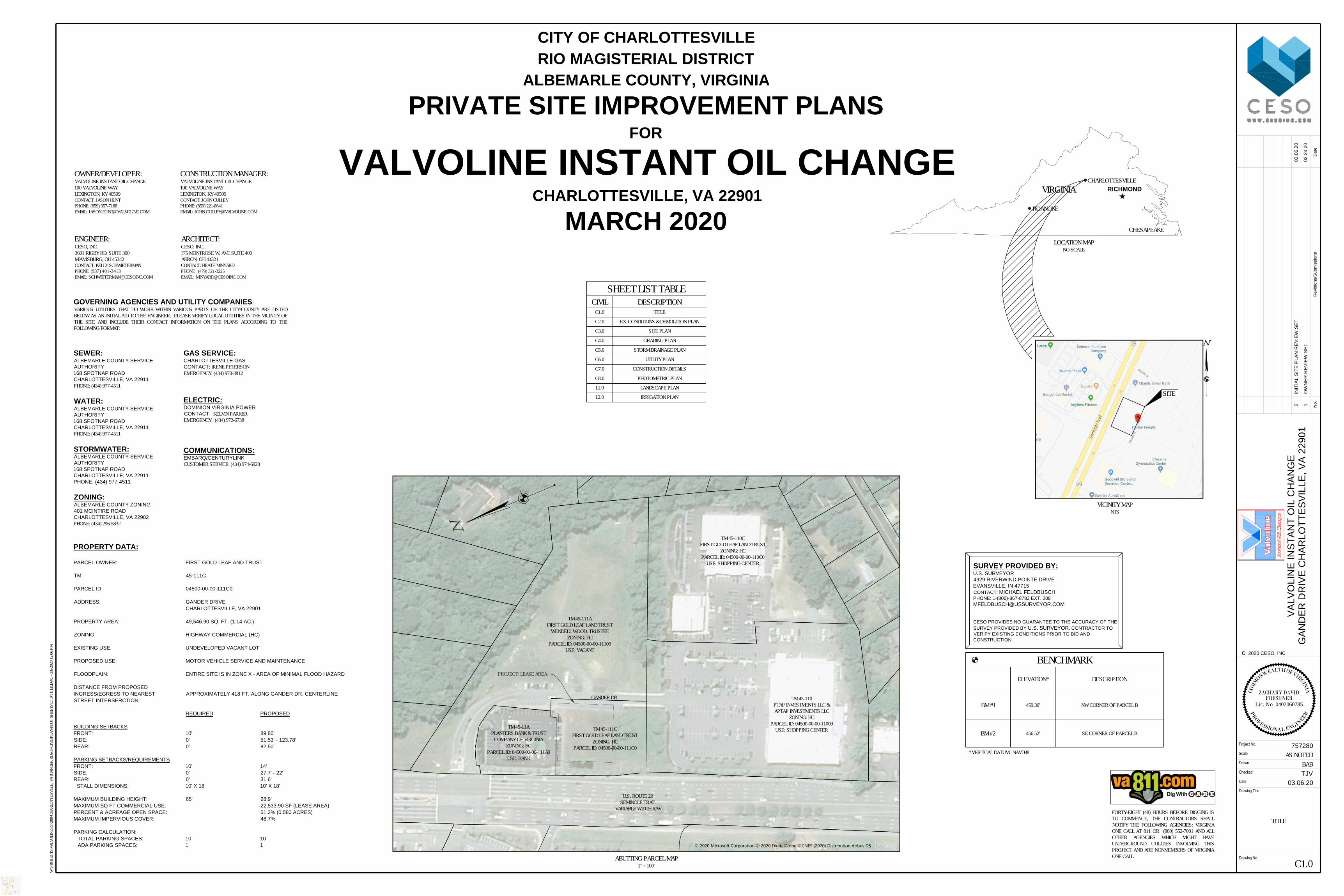
PROPERTY DATA:
PARCEL OWNER: FIRST GOLD LEAF AND TRUST
TM: 45-111C
PARCEL ID: 04500-00-00-111C0
ADDRESS: GANDER DRIVE
CHARLOTTESVILLE, VA 22901
PROPERTY AREA: 49,546.90 SQ. FT. (1.14 AC.)
ZONING: HIGHWAY COMMERCIAL (HC)
EXISTING USE: UNDEVELOPED VACANT LOT
PROPOSED USE: MOTOR VEHICLE SERVICE AND MAINTENANCE
FLOODPLAIN: ENTIRE SITE IS IN ZONE X - AREA OF MINIMAL FLOOD HAZARD
DISTANCE FROM PROPOSED
INGRESS/EGRESS TO NEAREST APPROXIMATELY 418 FT. ALONG GANDER DR. CENTERLINE
STREET INTERSERCTION
REQUIRED PROPOSED
BUILDING SETBACKS
FRONT: 10' 89.80'
SIDE: 0' 51.53' - 123.78'
REAR: 0' 82.50'
PARKING SETBACKS/REQUIREMENTS
FRONT: 10' 14'
SIDE: 0' 27.7' - 22'
REAR: 0' 31.6'
STALL DIMENSIONS: 10' X 18' 10' X 18'
MAXIMUM BUILDING HEIGHT: 65' 28.9'
MAXIMUM SQ FT COMMERCIAL USE: 22,533.90 SF (LEASE AREA)
PERCENT & ACREAGE OPEN SPACE: 51.3% (0.580 ACRES)
MAXIMUM IMPERVIOUS COVER: 48.7%
PARKING CALCULATION:
TOTAL PARKING SPACES: 10 10
ADA PARKING SPACES: 1 1
GOVERNING AGENCIES AND UTILITY COMPANIES:
VARIOUS UTILITIES THAT DO WORK WITHIN VARIOUS PARTS OF THE CITY/COUNTY ARE LISTEDBELOW AS AN INITIAL AID TO THE ENGINEER. PLEASE VERIFY LOCAL UTILITIES IN THE VICINITY OFTHE SITE AND INCLUDE THEIR CONTACT INFORMATION ON THE PLANS ACCORDING TO THEFOLLOWING FORMAT:
CITY OF CHARLOTTESVILLE
RIO MAGISTERIAL DISTRICT
ALBEMARLE COUNTY, VIRGINIA
PRIVATE SITE IMPROVEMENT PLANS
FOR
VALVOLINE INSTANT OIL CHANGE
CHARLOTTESVILLE, VA 22901
MARCH 2020
SURVEY PROVIDED BY:
U.S. SURVEYOR
4929 RIVERWIND POINTE DRIVE
EVANSVILLE, IN 47715
CONTACT: MICHAEL FELDBUSCH
PHONE: 1-(800)-867-8783 EXT. 208
CESO PROVIDES NO GUARANTEE TO THE ACCURACY OF THE
SURVEY PROVIDED BY U.S. SURVEYOR. CONTRACTOR TO
VERIFY EXISTING CONDITIONS PRIOR TO BID AND
CONSTRUCTION.
SEWER:
ALBEMARLE COUNTY SERVICE
AUTHORITY
168 SPOTNAP ROAD
CHARLOTTESVILLE, VA 22911
PHONE: (434) 977-4511
VICINITY MAPNTS
BENCHMARKELEVATION* DESCRIPTION
BM #1 459.30' NW CORNER OF PARCEL B
BM #2 456.52' SE CORNER OF PARCEL B
* VERTICAL DATUM: NAVD88
WATER:
ALBEMARLE COUNTY SERVICE
AUTHORITY
168 SPOTNAP ROAD
CHARLOTTESVILLE, VA 22911
PHONE: (434) 977-4511
STORMWATER:
ALBEMARLE COUNTY SERVICE
AUTHORITY
168 SPOTNAP ROAD
CHARLOTTESVILLE, VA 22911
PHONE: (434) 977-4511
ZONING:
ALBEMARLE COUNTY ZONING
401 MCINTIRE ROAD
CHARLOTTESVILLE, VA 22902
PHONE: (434) 296-5832
COMMUNICATIONS:
EMBARQ/CENTURYLINK
CUSTOMER SERVICE: (434) 974-6928
ELECTRIC:
DOMINION VIRGINIA POWER
CONTACT: KELVIN PARKEREMERGENCY: (434) 972-6738
GAS SERVICE:
CHARLOTTESVILLE GAS
CONTACT: IRENE PETERSONEMERGENCY: (434) 970-3812
FORTY-EIGHT (48) HOURS BEFORE DIGGING ISTO COMMENCE, THE CONTRACTORS SHALLNOTIFY THE FOLLOWING AGENCIES: VIRGINIAONE CALL AT 811 OR (800) 552-7001 AND ALLOTHER AGENCIES WHICH MIGHT HAVEUNDERGROUND UTILITIES INVOLVING THISPROJECT AND ARE NONMEMBERS OF VIRGINIAONE CALL.
CONSTRUCTION MANAGER:VALVOLINE INSTANT OIL CHANGE100 VALVOLINE WAYLEXINGTON, KY 40509CONTACT: JOHN CULLEYPHONE: (859) 221-8641EMAIL: [email protected]
OWNER/DEVELOPER:VALVOLINE INSTANT OIL CHANGE100 VALVOLINE WAYLEXINGTON, KY 40509CONTACT: JASON HUNTPHONE: (859) 357-7188EMAIL: [email protected]
ARCHITECT:CESO, INC.175 MONTROSE W. AVE SUITE 400AKRON, OH 44321CONTACT: HEATH MINYARDPHONE (479) 321-3225EMAIL: [email protected]
ENGINEER:CESO, INC.3601 RIGBY RD. SUITE 300MIAMISBURG, OH 45342CONTACT: KELLY SCHWIETERMANPHONE: (937) 401-3413EMAIL: [email protected]
C1.0
TITLE
BABAS NOTED
Date
Drawing No.
Project No.
Scale
Checked
Drawn
Drawing Title
2020 CESO, INCc
Da
te
No
.R
evisio
ns/S
ub
missio
ns
TJV
VA
LV
OL
IN
E IN
ST
AN
T O
IL
C
HA
NG
E
GA
ND
ER
D
RIV
E C
HA
RL
OT
TE
SV
IL
LE
, V
A 2
29
01
757280
03.06.20
02.24.20
OW
NE
R R
EV
IE
W S
ET
W:\P
ROJE
CTS\
VALV
OLIN
E\75
7280
-CHA
RLOT
TESV
ILLE,
VA
(GAN
DER
RD)\0
3-CI
VIL\P
LAN\
PLOT
SHE
ETS\
C1.0
TITL
E.DW
G - 3
/6/20
20 12
:06 P
M
1
03.06.20
IN
IT
IA
L S
IT
E P
LA
N R
EV
IE
W S
ET
2
COM
MONWEALTH OF VIRGIN
IA
PR
OFESSIONAL ENGIN
EER
FRESHNERLic. No. 0402060785
ZACHARY DAVID
LOCATION MAPNO SCALE
VIRGINIA RICHMOND
ROANOKE
CHARLOTTESVILLE
CHESAPEAKE
SITE
ABUTTING PARCEL MAP1" = 100'
TM 45-111AFIRST GOLD LEAF LAND TRUST
WENDELL WOOD, TRUSTEEZONING: HC
PARCEL ID: 04500-00-00-11100USE: VACANT
TM 45-110CFIRST GOLD LEAF LAND TRUST
ZONING: HCPARCEL ID: 04500-00-00-110C0
USE: SHOPPING CENTER
TM 45-110PTAP INVESTMENTS LLC &APTAP INVESTMENTS LLC
ZONING: HCPARCEL ID: 04500-00-00-11000
USE: SHOPPING CENTERTM 45-11APLANTERS BANK & TRUST
COMPANY OF VIRGINIAZONING: HC
PARCEL ID: 04500-00-00-111A0USE: BANK
U.S. ROUTE 29SEMINOLE TRAIL
VARIABLE WIDTH R/W
PROJECT/ LEASE AREA
TM 45-111CFIRST GOLD LEAF LAND TRUST
ZONING: HCPARCEL ID: 04500-00-00-111C0
GANDER DR
SHEET LIST TABLECIVIL DESCRIPTION
C1.0 TITLE
C2.0 EX. CONDITIONS & DEMOLITION PLAN
C3.0 SITE PLAN
C4.0 GRADING PLAN
C5.0 STORM DRAINAGE PLAN
C6.0 UTILITY PLAN
C7.0 CONSTRUCTION DETAILS
C8.0 PHOTOMETRIC PLAN
L1.0 LANDSCAPE PLAN
L2.0 IRRIGATION PLAN
7.6'
VACANTNO BUILDINGS ATTIME OF SURVEY
STM
STM
STM
STM
STM
STM
STM
STM
STM
G
G
G
G
G
G
G
G
G
12''SAN
12''SAN
12''SAN
12''SAN
12''SAN
UGT
UGT
UGT
UGT
UGT
UGT
UGT
UGT
FOUND 1/2" REBAR W/LINCOLN CAP
FOUND 1/2" REBARW/ LINCOLN
CONTROL CAP
FOUND 1/2" REBAR W/LINCOLN CAP
FOUND 1/2" REBAR W/LINCOLN CAP
FOUND 1/2" REBAR W/LINCOLN CAP
30'
12.3'11.8'
12.0'
5.1'
5.1'
9.4'
69.4'
47.2'
10.0'
15.0'
15.0'
30.0'
15.0'
15.0'
20.0'
20.0'
18.7'
9.4'
20'
TBM #1
TBM #2
20.0'
LAT: 38°05'27" NLONG: 78°28'05" W
6.4'
22533.90 Sq. Feet0.52 Acres
LEASE
20.0'
CITY OF CHARLOTTESVILLE ESMTDB 4936
PGS92
ALBEMARLE SERVICEAUTHORITY ESMT
DB 4332PGS 284
CITY OFCHARLOTTESVILLE ESMT
DB 4936PGS92
ALBEMARLE SERVICEAUTHORITY ESMT
DB 4332PGS 284
& PWER ESMTDB 3925PGS 52
CENTRAL TELE. CO. ESMTDB 3919PGS 699
ALBEMARLESSWR. ESMTDB 997PGS 747 VIRGINIA ELEC.
& PWER ESMTDB 3925PGS 52
ALBEMARLE DEED ESMTDB 4859PGS 32
ALBEMARLE SERVICE AUTHORITY ESMTDB 4332PGS 284
457
456
460
459
459
456
458
457
456
455
453454
456
454
455
449
448
446
447446
447
447
446
445
448
449
446
456
453452
451450
445
456
455
457
454
459
8''W
8''W
8''W
8''W
8''W
8''W
8''W
VIRGINIA ELEC.
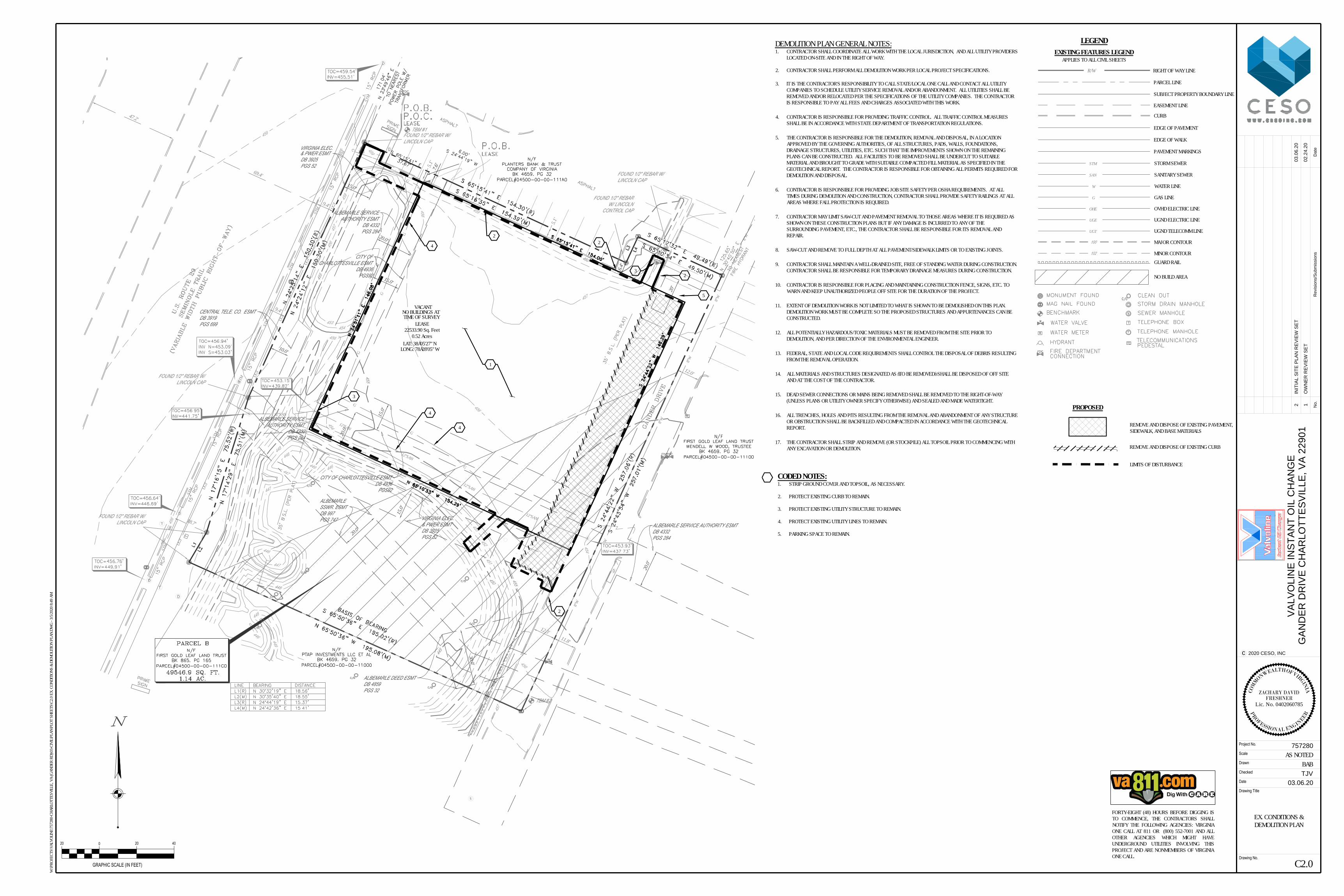
DEMOLITION PLAN GENERAL NOTES:1. CONTRACTOR SHALL COORDINATE ALL WORK WITH THE LOCAL JURISDICTION, AND ALL UTILITY PROVIDERS
LOCATED ON-SITE AND IN THE RIGHT OF WAY.
2. CONTRACTOR SHALL PERFORM ALL DEMOLITION WORK PER LOCAL PROJECT SPECIFICATIONS.
3. IT IS THE CONTRACTOR'S RESPONSIBILITY TO CALL STATE/LOCAL ONE CALL AND CONTACT ALL UTILITYCOMPANIES TO SCHEDULE UTILITY SERVICE REMOVAL AND/OR ABANDONMENT. ALL UTILITIES SHALL BEREMOVED AND/OR RELOCATED PER THE SPECIFICATIONS OF THE UTILITY COMPANIES. THE CONTRACTORIS RESPONSIBLE TO PAY ALL FEES AND CHARGES ASSOCIATED WITH THIS WORK.
4. CONTRACTOR IS RESPONSIBLE FOR PROVIDING TRAFFIC CONTROL. ALL TRAFFIC CONTROL MEASURESSHALL BE IN ACCORDANCE WITH STATE DEPARTMENT OF TRANSPORTATION REGULATIONS.
5. THE CONTRACTOR IS RESPONSIBLE FOR THE DEMOLITION, REMOVAL AND DISPOSAL, IN A LOCATIONAPPROVED BY THE GOVERNING AUTHORITIES, OF ALL STRUCTURES, PADS, WALLS, FOUNDATIONS,DRAINAGE STRUCTURES, UTILITIES, ETC. SUCH THAT THE IMPROVEMENTS SHOWN ON THE REMAININGPLANS CAN BE CONSTRUCTED. ALL FACILITIES TO BE REMOVED SHALL BE UNDERCUT TO SUITABLEMATERIAL AND BROUGHT TO GRADE WITH SUITABLE COMPACTED FILL MATERIAL AS SPECIFIED IN THEGEOTECHNICAL REPORT. THE CONTRACTOR IS RESPONSIBLE FOR OBTAINING ALL PERMITS REQUIRED FORDEMOLITION AND DISPOSAL.
6. CONTRACTOR IS RESPONSIBLE FOR PROVIDING JOB SITE SAFETY PER OSHA REQUIREMENTS. AT ALLTIMES DURING DEMOLITION AND CONSTRUCTION, CONTRACTOR SHALL PROVIDE SAFETY RAILINGS AT ALLAREAS WHERE FALL PROTECTION IS REQUIRED.
7. CONTRACTOR MAY LIMIT SAW-CUT AND PAVEMENT REMOVAL TO THOSE AREAS WHERE IT IS REQUIRED ASSHOWN ON THESE CONSTRUCTION PLANS BUT IF ANY DAMAGE IS INCURRED TO ANY OF THESURROUNDING PAVEMENT, ETC., THE CONTRACTOR SHALL BE RESPONSIBLE FOR ITS REMOVAL ANDREPAIR.
8. SAW-CUT AND REMOVE TO FULL DEPTH AT ALL PAVEMENT/SIDEWALK LIMITS OR TO EXISTING JOINTS.
9. CONTRACTOR SHALL MAINTAIN A WELL-DRAINED SITE, FREE OF STANDING WATER DURING CONSTRUCTION.CONTRACTOR SHALL BE RESPONSIBLE FOR TEMPORARY DRAINAGE MEASURES DURING CONSTRUCTION.
10. CONTRACTOR IS RESPONSIBLE FOR PLACING AND MAINTAINING CONSTRUCTION FENCE, SIGNS, ETC. TOWARN AND KEEP UNAUTHORIZED PEOPLE OFF SITE FOR THE DURATION OF THE PROJECT.
11. EXTENT OF DEMOLITION WORK IS NOT LIMITED TO WHAT IS SHOWN TO BE DEMOLISHED ON THIS PLAN.DEMOLITION WORK MUST BE COMPLETE SO THE PROPOSED STRUCTURES AND APPURTENANCES CAN BECONSTRUCTED.
12. ALL POTENTIALLY HAZARDOUS/TOXIC MATERIALS MUST BE REMOVED FROM THE SITE PRIOR TODEMOLITION, AND PER DIRECTION OF THE ENVIRONMENTAL ENGINEER.
13. FEDERAL, STATE AND LOCAL CODE REQUIREMENTS SHALL CONTROL THE DISPOSAL OF DEBRIS RESULTINGFROM THE REMOVAL OPERATION.
14. ALL MATERIALS AND STRUCTURES DESIGNATED AS “TO BE REMOVED” SHALL BE DISPOSED OF OFF SITEAND AT THE COST OF THE CONTRACTOR.
15. DEAD SEWER CONNECTIONS OR MAINS BEING REMOVED SHALL BE REMOVED TO THE RIGHT-OF-WAY(UNLESS PLANS OR UTILITY OWNER SPECIFY OTHERWISE) AND SEALED AND MADE WATERTIGHT.
16. ALL TRENCHES, HOLES AND PITS RESULTING FROM THE REMOVAL AND ABANDONMENT OF ANY STRUCTUREOR OBSTRUCTION SHALL BE BACKFILLED AND COMPACTED IN ACCORDANCE WITH THE GEOTECHNICALREPORT.
17. THE CONTRACTOR SHALL STRIP AND REMOVE (OR STOCKPILE) ALL TOPSOIL PRIOR TO COMMENCING WITHANY EXCAVATION OR DEMOLITION.
CODED NOTES:1. STRIP GROUND COVER AND TOPSOIL, AS NECESSARY.
2. PROTECT EXISTING CURB TO REMAIN.
3. PROTECT EXISTING UTILITY STRUCTURE TO REMAIN.
4. PROTECT EXISTING UTILITY LINES TO REMAIN.
5. PARKING SPACE TO REMAIN.
LEGEND
PROPOSED
REMOVE AND DISPOSE OF EXISTING CURB
0
GRAPHIC SCALE (IN FEET)
20 20 40
EXISTING FEATURES LEGENDAPPLIES TO ALL CIVIL SHEETS
RIGHT OF WAY LINE
EASEMENT LINE
EDGE OF PAVEMENT
PARCEL LINE
CURB
PAVEMENT MARKINGS
R/W
GAS LINEG
SANITARY SEWERSAN
WATER LINEW
OVHD ELECTRIC LINEOHE
UGND ELECTRIC LINEUGE
UGND TELECOMM LINEUGT
MINOR CONTOUR
100
102
MAJOR CONTOUR
EDGE OF WALK
SUBJECT PROPERTY BOUNDARY LINE
STORM SEWERSTM
C2.0
EX. CONDITIONS &DEMOLITION PLAN
BABAS NOTED
Date
Drawing No.
Project No.
Scale
Checked
Drawn
Drawing Title
2020 CESO, INCc
Da
te
No
.R
evisio
ns/S
ub
missio
ns
TJV
VA
LV
OL
IN
E IN
ST
AN
T O
IL
C
HA
NG
E
GA
ND
ER
D
RIV
E C
HA
RL
OT
TE
SV
IL
LE
, V
A 2
29
01
757280
03.06.20
02.24.20
OW
NE
R R
EV
IE
W S
ET
W:\P
ROJE
CTS\
VALV
OLIN
E\75
7280
-CHA
RLOT
TESV
ILLE,
VA
(GAN
DER
RD)\0
3-CI
VIL\P
LAN\
PLOT
SHE
ETS\
C2.0
EX. C
ONDI
TION
S &
DEMO
LITIO
N PL
AN.D
WG
- 3/5/
2020
8:49
AM
1
03.06.20
IN
IT
IA
L S
IT
E P
LA
N R
EV
IE
W S
ET
2
COM
M
ONWEALTH OF VIRGINIA
PR
OFESSIONAL ENGIN
EER
FRESHNERLic. No. 0402060785
ZACHARY DAVID
FORTY-EIGHT (48) HOURS BEFORE DIGGING ISTO COMMENCE, THE CONTRACTORS SHALLNOTIFY THE FOLLOWING AGENCIES: VIRGINIAONE CALL AT 811 OR (800) 552-7001 AND ALLOTHER AGENCIES WHICH MIGHT HAVEUNDERGROUND UTILITIES INVOLVING THISPROJECT AND ARE NONMEMBERS OF VIRGINIAONE CALL.
GUARD RAIL
1
4
4
4
3
3
22
LIMITS OF DISTURBANCE
2
2
REMOVE AND DISPOSE OF EXISTING PAVEMENT,SIDEWALK, AND BASE MATERIALS
NO BUILD AREA
5

D
S
D
S
D
S
D
S
D
S
VIOCGANDER DRIVE
A = 2,080 SF; H = 28'-11"
D
S
D
S
D
S
D
S
D
S
E
VIOCGANDER DRIVE
A = 2,080 SF; H = 28'-11"
7.6'
STM
STM
STM
STM
STM
STM
STM
STM UG
T
UGT
UGT
UGT
UGT
UGT
UGT
UGT
10.0'
15.0'
15.0'
30.0'
15.0'
15.0'
20.0'
20.0'
20'
20.0'
6.4'
20.0'
CITY OF CHARLOTTESVILLE ESMTDB 4936
PGS92
ALBEMARLE SERVICEAUTHORITY ESMT
DB 4332PGS 284
CITY OFCHARLOTTESVILLE ESMT
DB 4936PGS92
ALBEMARLE SERVICEAUTHORITY ESMT
DB 4332PGS 284
& PWER ESMTDB 3925PGS 52
CENTRAL TELE. CO. ESMTDB 3919PGS 699
ALBEMARLESSWR. ESMTDB 997PGS 747 VIRGINIA ELEC.
& PWER ESMTDB 3925PGS 52
ALBEMARLE DEED ESMTDB 4859PGS 32
ALBEMARLE SERVICE AUTHORITY ESMTDB 4332PGS 284
VIRGINIA ELEC. SITE PLAN GENERAL NOTES:1. ALL WORK AND MATERIALS SHALL COMPLY WITH ALL APPLICABLE LOCAL, STATE, AND FEDERAL HEALTH AND SAFETY STANDARDS, INCLUDING
BUT NOT LIMITED TO O.S.H.A. STANDARDS.
2. THE CONTRACTOR SHALL OBTAIN FINAL APPROVALS/PERMITTING AND INSPECTION AS NECESSARY PRIOR TO CONSTRUCTION.
3. CONTRACTOR SHALL REFER TO THE ARCHITECTURAL PLANS FOR LOCATIONS AND DIMENSIONS OF DUMPSTER ENCLOSURE, BUILDINGDIMENSIONS, BUILDING UTILITY ENTRANCE LOCATIONS AND SITE LIGHTING ELECTRICAL LAYOUT.
4. REFER TO CONSTRUCTION DETAILS / GEOTECHNICAL REPORT FOR PAVEMENT SECTION RECOMMENDATIONS.
5. CONTRACTOR IS RESPONSIBLE FOR PROVIDING TRAFFIC CONTROL. ALL TRAFFIC CONTROL MEASURES SHALL BE IN ACCORDANCE WITH THESTATE SUPPLEMENT TO THE NATIONAL MANUAL OF UNIFORM TRAFFIC CONTROL DEVICES (LATEST EDITION).
6. CONTRACTOR IS RESPONSIBLE FOR PLACING AND MAINTAINING CONSTRUCTION FENCE, SIGNS, ETC. TO WARN AND KEEP UNAUTHORIZEDPEOPLE OFF SITE FOR THE DURATION OF THE PROJECT.
7. CONTRACTOR IS RESPONSIBLE FOR PROVIDING JOB SITE SAFETY PER OSHA REQUIREMENTS. AT ALL TIMES DURING DEMOLITION ANDCONSTRUCTION, CONTRACTOR SHALL PROVIDE SAFETY RAILINGS AT ALL AREAS WHERE FALL PROTECTION IS REQUIRED.
8. ALL SIGNAGE SHALL COMPLY WITH THE STATE SUPPLEMENT TO THE MANUAL OF UNIFORM TRAFFIC CONTROL DEVICES.
9. ALL PAVEMENT MARKINGS AND STRIPING SHALL COMPLY WITH THE STATE DOT AND THE STATE SUPPLEMENT TO THE MANUAL OF UNIFORMTRAFFIC CONTROL DEVICES.
a. LANE LINE: 6” WHITE
b. PARKING STALLS: 4” WHITE
c. STOP LINE: 24” WHITE
d. CROSSWALKS: TRANSVERSE LINES WITH DIAGONAL MARKINGS (GAP BETWEEN TRANSVERSE LINES SHALL BE 4') ALL PAINTED WHITE.
e. HANDICAPPED STALLS: 4" YELLOW OUTLINE, WITH 4" BLUE INTERIOR AND BLUE HANDICAPPED SYMBOLS
10. BOLLARDS SHALL BE PLACED TO PROTECT GAS METER, ELECTRICAL AND TELEPHONE EQUIPMENT, AND DUMPSTER ENCLOSURE.
11. ALL LIGHT POLES TO BE LOCATED 2' FROM BACK OF CURB AS MEASURED FROM THE FACE OF POLE FOUNDATIONS, UNLESS OTHERWISENOTED ON PLANS.
12. ANY SIDEWALK, EXISTING CURB, OR PAVEMENT DAMAGED DURING CONSTRUCTION SHALL BE REPLACED.
13. PROPOSED CURB TO BE 6" HIGH UNLESS OTHERWISE NOTED.
14. HANDICAP REQUIREMENTS SHOWN ON THE DRAWINGS ARE MINIMUM REQUIREMENTS. DEVELOPMENT SHALL BE IN ACCORDANCE WITHFEDERAL AND LOCAL REQUIREMENTS FOR HANDICAP ACCESSIBILITY, INCLUDING BUT NOT LIMITED TO THE AMERICANS WITH DISABILITIES ACTACCESSIBILITY GUIDELINES.
15. PRIOR TO FINAL ACCEPTANCE OF STORE BY OWNER, THE SITE SHALL BE CLEAN OF ALL DEBRIS AND TRASH.
16. ALL CURB RADII TO BE 5', UNLESS OTHERWISE NOTED ON PLAN.
CODED NOTES:
1. ADA ACCESSIBLE PARKING SPACE WITH SIGNAGE AND PAVEMENT MARKINGS. REFER TO CONSTRUCTION DETAILS.
2. ADA ACCESSIBLE RAMP WITH DETECTIBLE WARNING. REFER TO CONSTRUCTION DETAILS.
3. FLUSH CURB
4. TRANSITION CURB FROM FLUSH TO FULL HEIGHT IN 10'
5. PROPOSED PAVEMENT MARKINGS.
6. ASPHALT PAVEMENT, PER CONSTRUCTION DETAILS
7. CONCRETE WALK, PER CONSTRUCTION DETAILS
8. CONCRETE PAVEMENT WITH BLACK COLORTOP SEALANT, PER CONSTRUCTION DETAILS.
9. PROPOSED MONUMENT SIGN, PER SIGNAGE PLAN
10. DUMPSTER ENCLOSURE & CONCRETE PAD. REFER TO ARCHITECTURAL PLANS FOR PAVEMENT AND ENCLOSURE DETAILS.
11. LIGHT POLE BASE, PER UTILITY DETAILS.
12. PROPOSED BIKE RACK, PER CONSTRUCTION DETAILS.
13. GENERAL CONTRACTOR TO PROVIDE CONDUIT FOR BELL RINGER. CONDUIT TO BE INSTALLED UNDER CONCRETE SIDEWALK,
ADJACENT TO BUILDING, AND STUB OUT OF CONCRETE CURB. REFER TO CONSTRUCTION DETAILS AND ARCHITECTURAL
DRAWINGS FOR ADDITIONAL INFORMATION.
14. CONDENSING UNIT. REFER TO MECHANICAL PLANS.
PROPOSED
CONCRETE CURB
PAVEMENT/WALK
BUILDING
LEGEND
EXISTINGREFER TO EX. CONDITIONS AND DEMOLITION
PLAN SHEET FOR EXISTING FEATURES LEGEND
0
GRAPHIC SCALE (IN FEET)
20 20 40
ASPHALT PAVEMENT
7 PARKING SPACE COUNT
CONCRETE
ELECTRIC POLE
CONCRETE PAVEMENT WITHBLACK COLORTOP SEALANT
ENLARGED PLAN: ACCESSIBLE PARKING AREA1'' = 10'
DETECTABLE WARNING MAT.
CONCRETE BUMPER BLOCK
C3.0
SITE PLAN
BABAS NOTED
Date
Drawing No.
Project No.
Scale
Checked
Drawn
Drawing Title
2020 CESO, INCc
Da
te
No
.R
evisio
ns/S
ub
missio
ns
TJV
VA
LV
OL
IN
E IN
ST
AN
T O
IL
C
HA
NG
E
GA
ND
ER
D
RIV
E C
HA
RL
OT
TE
SV
IL
LE
, V
A 2
29
01
757280
03.06.20
02.24.20
OW
NE
R R
EV
IE
W S
ET
W:\P
ROJE
CTS\
VALV
OLIN
E\75
7280
-CHA
RLOT
TESV
ILLE,
VA
(GAN
DER
RD)\0
3-CI
VIL\P
LAN\
PLOT
SHE
ETS\
C4.0
SITE
PLA
N.DW
G - 3
/6/20
20 9:
45 A
M
1
03.06.20
IN
IT
IA
L S
IT
E P
LA
N R
EV
IE
W S
ET
2
COM
MONWEALTH OF VIRGIN
IA
PR
OFESSIONAL ENGIN
EER
FRESHNERLic. No. 0402060785
ZACHARY DAVID
FORTY-EIGHT (48) HOURS BEFORE DIGGING ISTO COMMENCE, THE CONTRACTORS SHALLNOTIFY THE FOLLOWING AGENCIES: VIRGINIAONE CALL AT 811 OR (800) 552-7001 AND ALLOTHER AGENCIES WHICH MIGHT HAVEUNDERGROUND UTILITIES INVOLVING THISPROJECT AND ARE NONMEMBERS OF VIRGINIAONE CALL.
5.00
11.00
14.005.50
5.50
6.00
10.50
R2.50
R12.00
R6.00R2.50
R5.00
R2.50
8.00 8.00
10.00
10.00(TYP.)
18.00(TYP.)
2.00(TYP.)
5.00
7.00
6.005.19
5.50
5.50
43.00
40.00
24.00
4.50
24.00
56.00
20.00
16.00
16.00
1
2
2 3
3
5(TYP.)
6
6
7
7
10
12
14
6
4
5.00
13
4
4
4
51.53
89.80
15.50
5.00
5.506.00
10.50
8.0010.00(TYP.)
33.42
8.00
5.00
6.00
43.00
15.50
11.50
10.00(TYP.)2.00
5.50
18.00(TYP.)
43.00
5.00
39.00
26.52
56.00
82.50
11
11
11
R3.50
R6.00R2.50
R5.00
R2.50
R2.25
R12.00
R5.00R5.00
R2.00
11
11
11
9
8
8
7
7
6
6
3
3
2
R5.00
2
1
6
4
5.00
43.00
5(TYP.)
5
(TYP.)
5(TYP.)
8
8
18.00
21.33
123.78
R10.00
20.00
40.00
24.00
20.00
20.00
18.00
21.33
5.50
5.50
7
R5.00
18.00
20.00
24.00
16.00
16.00
R24.00
R24.00
R2.50
20.00
5.00
3
ACCESSAGREEMENTALLOWSVALVOLINE TOUSE STREETPARKING
7.6'
STM
STM
STM
STM
STM
STM
STM
STM
G
G
G
G
G
G
G
G
G
SAN SAN
SAN
SAN
SAN
SAN
UGT
UGT
UGT
UGT
UGT
UGT
UGT
UGT
30'
12.3'11.8'
12.0'
5.1'
5.1'
9.4'
69.4'
18.7'
9.4'
6.4'
457
456
460
459
459
456
458
457
456
455
453454
456
454
455
449
448
446
447446
447
447
446
445
448
449
446
456
453452
451450
445
456
455
457
454
459
W
W
W
W
W
W
W
W
UGE
UGE
UGE
UGEUG
T
UGT
UGT
UGT
M
D
S
D
S
D
S
D
S
D
S
SAN
SAN
SAN
SAN COCO
GAS
E
FM
FM
STM
STM
STM
STM
STM
STM
CO
CO
VIOCGANDER DRIVE
A = 2,080 SF; H = 28'-11"
W
W
TC=456.52BC=456.02
TC=456.52BC=456.02
TC=456.98BC=456.48
TC=456.67BC=456.17
TC=457.72BC=457.22
TC=457.93BC=457.43
456.78456.68TC=456.83BC=456.83
TC=456.94BC=456.94
TC=456.94BC=456.94
TC=456.94BC=456.44
TC=456.53BC=456.03
TC=455.34BC=454.84
TC=455.40BC=454.90
TC=455.09BC=454.59
TC=455.14BC=454.64
TC=455.07BC=454.57
TC=455.19BC=454.69
TC=456.83BC=456.33
TC=456.83BC=456.33
TC=456.83BC=456.33
TC=456.93BC=456.43
TC=456.93BC=456.43
TC=456.89BC=456.39
TC=457.09BC=456.59
TC=456.94BC=456.94
TC=456.93BC=456.43
TC=456.94BC=456.44
TC=456.63BC=456.13
TC=456.68BC=456.18
TC=456.94BC=456.94
TC=458.26BC=457.76
TC=458.49BC=457.99
TC=458.76BC=458.26
TC=458.94BC=458.44
TC=456.98 (M.E.)BC=456.48 (M.E.)
TC=456.77BC=456.27
TC=457.00BC=456.50
TC=457.75BC=457.25
TC=458.19BC=457.69
457.14
456.44
TC=456.90BC=456.40
TC=458.06BC=457.56
TC=456.54BC=456.04
TC=456.83BC=456.33
TC=456.35BC=455.85
TC=455.88BC=455.38 454.43
455.58
TC=456.47BC=455.97
TC=455.20BC=454.70
454.55 (M.E.)
454.78 (M.E.)
455.54 (M.E.)
455.89 (M.E.)
-3.0:1
457
455
456
456
455456456
456
TC=457.04BC=456.54
TC=455.31 (M.E.)BC=454.81 (M.E.)
455.41 (M.E.)
TC=454.83BC=454.33
TC=455.20BC=454.70
TC=455.56BC=455.06
456
457
457
455
DS
SAN
SAN
COCO
STM
STM
STM
STM
TC=456.94BC=456.94
TC=456.94BC=456.44
TC=456.53BC=456.03
TC=456.43BC=455.93
TC=456.84BC=456.34
TC=456.83BC=456.33
TC=456.15BC=456.15
TC=456.04BC=456.04
456.12455.96
TC=456.83BC=456.33
TC=456.83BC=456.33
TC=455.07BC=454.57
TC=455.14BC=454.64
TC=455.19BC=454.69
TC=455.56BC=455.06
TC=455.34BC=454.84
TC=456.81BC=456.24
TC=456.68BC=456.14
457
UGE
M
DS
DS
DS
GAS
GASGAS
FM
STMSTMSTMSTM
WW
W
TC=457.64BC=457.14
TC=457.67BC=457.17
TC=457.93BC=457.43
457.14
456.44
456.78
456.78
457.14457.34
457.64
456.89
456.98
456.93
456.68TC=456.74BC=456.74
TC=456.83BC=456.83
TC=457.72BC=457.22
TC=457.45BC=456.95
TC=456.68BC=456.18
TC=456.68BC=456.18
TC=456.93BC=456.43
TC=456.98BC=456.48
TC=456.68BC=456.18
TC=456.55BC=456.05
TC=456.55BC=456.05
SW=456.93SW=456.92
SW=457.04SW=457.04
SW=457.04
TC=457.04BC=456.54
TC=456.94BC=456.94
TC=456.93BC=456.43 TC=456.94
BC=456.94
457
GRADING PLAN NOTES:1. ONLY VIRGIN MATERIALS SHALL BE USED UNLESS APPROVED IN WRITING BY A VALVOLINE INSTANT OIL CHANGE REPRESENTATIVE.
2. ALL SITE WORK, MATERIALS OF CONSTRUCTION, AND CONSTRUCTION METHODS SHALL COMPLY WITH LOCAL MUNICIPALITY, LOCAL COUNTY, AND STATE DEPARTMENT OFTRANSPORTATION MATERIAL AND CONSTRUCTION SPECIFICATIONS.
3. THE CONTRACTOR IS SOLELY RESPONSIBLE FOR DETERMINING ACTUAL LOCATIONS AND ELEVATIONS OF ALL UTILITIES, INCLUDING SERVICES. PRIOR TO CONSTRUCTION, THECONTRACTOR SHALL CONTACT THE STATE ONE CALL SYSTEM AT LEAST THREE (3) WORKING DAYS BEFORE START OF WORK AND VERIFY ALL EXISTING UTILITY LOCATIONS.
4. ALL PIPES SHALL BE LAID ON STRAIGHT ALIGNMENTS AND EVEN GRADES USING A PIPE LASER OR OTHER ACCURATE METHOD.
5. THE CONTRACTOR SHALL COMPACT PIPE BACKFILL IN MAX. 6” LOOSE LIFTS TO 95% OF THE MAXIMUM DRY DENSITY PER ASTM D1557, ACCORDING TO THE PIPE BEDDINGDETAILS. TRENCH BOTTOM SHALL BE STABLE IN HIGH GROUNDWATER AREAS. A PIPE FOUNDATION SHALL BE USED IN AREAS OF ROCK EXCAVATION.
6. CONTRACTOR SHALL PROVIDE ALL BENDS, FITTINGS, ADAPTERS, ETC., AS REQUIRED FOR PIPE CONNECTIONS TO BUILDING/CANOPY STUB-OUTS, INCLUDING ROOF/FOOTINGDRAIN CONNECTIONS TO ROOF LEADERS AND TO STORM DRAINAGE SYSTEM.
7. TOPSOIL SHALL BE STRIPPED AND STOCKPILED FOR USE IN FINAL LANDSCAPING.
8. MANHOLE RIMS AND STORM INLET GRATES SHALL BE SET TO ELEVATIONS SHOWN. SET ALL EXISTING MANHOLE FRAMES AND COVERS, STORM INLET GRATES, VALVE BOXES,ETC., TO BE RAISED OR LOWERED, TO PROPOSED FINISHED GRADE, FLUSH WITH THE ADJACENT GRADE.
9. UNDERDRAINS MAY BE ADDED, IF DETERMINED NECESSARY BY THE ENGINEER OR CONSTRUCTION MANAGER, AFTER SUBGRADE IS ROUGH GRADED.
10. ALL EXISTING TOPOGRAPHICAL FEATURES (SPOT ELEVATIONS, CONTOURS, INVERTS, ETC.) CAN HAVE A TOLERANCE DIFFERENCE OF 6”+/- DEPENDING ON FIELD CONDITIONS ATTHE TIME OF THE FIELD SURVEY. CONTRACTOR TO VERIFY ALL EXISTING TOPOGRAPHICAL FEATURES PRIOR TO CONSTRUCTION, AND ADVISE OWNER OF ANY DISCREPANCIES.
11. THE CONTRACTOR SHALL RESTORE ANY STRUCTURE, PIPE, UTILITY, PAVEMENT, CURBS, SIDEWALKS, LANDSCAPED AREAS, ETC. DISTURBED DURING CONSTRUCTION TO THEORIGINAL CONDITION OR BETTER.
12. THE CONTRACTOR SHALL SUBMIT SHOP DRAWINGS OF MATERIALS AND STRUCTURES TO THE CONSTRUCTION MANAGER FOR REVIEW AND APPROVAL PRIOR TO FABRICATION.
13. THE CONTRACTOR SHALL PRESERVE EXISTING VEGETATION WHERE POSSIBLE AND/OR AS NOTED ON DRAWINGS. REFER TO EROSION AND SEDIMENTATION PLAN FOR LIMIT OFDISTURBANCE AND NOTES.
14. THE CONTRACTOR SHALL COMPACT FILL UNDER ALL PARKING, BUILDING, AND DRIVE AREAS AS DIRECTED BY THE GEOTECHNICAL REPORT AND/OR GEOTECHNICAL ENGINEER.
15. THE CONTRACTOR IS RESPONSIBLE FOR THE REMOVAL AND DISPOSAL OF ALL RUBBISH, TRASH, DEBRIS, AND ORGANIC MATERIAL IN A LAWFUL MANNER.
16. THE CONTRACTOR SHALL BE ADVISED THAT ALL EXCAVATION IS CONSIDERED UNCLASSIFIED AND THAT IT SHALL BE RESPONSIBLE FOR ALL MEANS, METHODS, AND MATERIALS OFCONSTRUCTION TO COMPLETE CONSTRUCTION AS DESIGNED. ADDITIONALLY, THE CONTRACTOR SHALL BE RESPONSIBLE FOR THE OFF SITE DISPOSAL OF ANY AND ALL EXCESSOR UNSUITABLE MATERIAL UNABLE TO BE PLACED ON SITE AND THE IMPORTATION OF ANY BORROW MATERIAL NECESSARY TO COMPLETE THE JOB.
17. ALL EXCAVATION AND GRADING CONSTRUCTION SHALL BE PERFORMED IN ACCORDANCE WITH THE GEOTECHNICAL ENGINEERING REPORT.
18. SITE GRADING SHALL BE PERFORMED TO PROVIDE POSITIVE DRAINAGE TO STORM INLETS AND TO PRECLUDE THE PONDING OF WATER ON SITE.
19. VERIFY REQUIRED SPOT ELEVATIONS/GRADING IN THE VICINITY OF THE BUILDINGS WITH THE ARCHITECTURAL PLANS.
20. ALL ACCESSIBLE PARKING SPACES TO HAVE A MAXIMUM SLOPE OF 2% IN ANY DIRECTION.
21. ALL SIDEWALKS, PATIO AREAS, AND ACCESSIBLE ROUTES TO THE BUILDING ARE TO HAVE A MAXIMUM CROSS SLOPE OF 2% AND A MAXIMUM LONGITUDINAL SLOPE OF 5%, UNLESSIN AN APPROVED ADA RAMP.
22. CONTRACTOR TO FIELD VERIFY PROPOSED AND EXISTING GRADES, SLOPES, ETC., FOR PROPOSED ACCESSIBLE PARKING AREAS, RAMPS, ETC., WITH ARCHITECT, PRIOR TOCONSTRUCTION.
23. LOCATIONS OF EXISTING UNDERGROUND UTILITIES ARE TAKEN FROM FIELD OBSERVATION, UTILITY MAPS, ETC., AND ARE NOT ASSUMED TO BE ACCURATE. PRIOR TO ANYCONSTRUCTION ACTIVITIES, CONTRACTOR TO DIG TEST PITS AT ALL PROPOSED UTILITY CROSSINGS, TO VERIFY LOCATION, DEPTH, SIZE, ETC. OF EXISTING UNDERGROUNDUTILITIES, AND CONFIRM NEW UTILITY LINES CAN BE INSTALLED AS PROPOSED. ADVISE VALVOLINE CONSTRUCTION MANAGER IMMEDIATELY OF ANY CONFLICTS ORDISCREPANCIES.
SLOPE ARROW
TOP OF CURB ELEV.BOTTOM OF CURB ELEV.
TC=XXX.XXBC=XXX.XX
X.XX%
MAJOR CONTOUR
MINOR CONTOUR
BUILDING
XXX.XX
MATCH EXISTING ELEVATION(M.E.)
BOTTOM OF CURB
TOP OF CURB
CLEAN OUT
FINISHED GRADE ELEVATION
0
GRAPHIC SCALE (IN FEET)
20 20 40
CO
DOWNSPOUT CONNECTIONDS
STORM SEWERSTM
322
320
BC
TC
CODED NOTES:
1. TRANSITION CURB FROM FLUSH TO FULL HEIGHT IN 10' (UNLESS TAPER
LENGTH NOTED IN PLAN)
2. ADA ACCESSIBLE RAMP WITH DETECTABLE WARNING. REFER TO
CONSTRUCTION DETAILS
3. TRANSITION FROM EXISTING CURB TO BACK OF CURB. SEE DETAIL
THIS SHEET.
MANHOLE
CATCH BASIN
CURB INLET
GRADE BREAK
LEGENDEXISTING
PROPOSED
REFER TO EX. CONDITIONS AND DEMOLITIONPLAN SHEET FOR EXISTING LEGEND ITEMS
C4.0
GRADING PLAN
NETAS NOTED
Date
Drawing No.
Project No.
Scale
Checked
Drawn
Drawing Title
2020 CESO, INCc
Da
te
No
.R
evisio
ns/S
ub
missio
ns
TJV
VA
LV
OL
IN
E IN
ST
AN
T O
IL
C
HA
NG
E
GA
ND
ER
D
RIV
E C
HA
RL
OT
TE
SV
IL
LE
, V
A 2
29
01
757280
03.06.20
02.24.20
OW
NE
R R
EV
IE
W S
ET
W:\P
ROJE
CTS\
VALV
OLIN
E\75
7280
-CHA
RLOT
TESV
ILLE,
VA
(GAN
DER
RD)\0
3-CI
VIL\P
LAN\
PLOT
SHE
ETS\
C5.0
GRAD
ING
PLAN
.DW
G - 3
/6/20
20 9:
45 A
M
1
03.06.20
IN
IT
IA
L S
IT
E P
LA
N R
EV
IE
W S
ET
2
COM
M
ONWEALTH OF VIRGINIA
PR
OFESSIONAL ENGIN
EER
FRESHNERLic. No. 0402060785
ZACHARY DAVID
FORTY-EIGHT (48) HOURS BEFORE DIGGING ISTO COMMENCE, THE CONTRACTORS SHALLNOTIFY THE FOLLOWING AGENCIES: VIRGINIAONE CALL AT 811 OR (800) 552-7001 AND ALLOTHER AGENCIES WHICH MIGHT HAVEUNDERGROUND UTILITIES INVOLVING THISPROJECT AND ARE NONMEMBERS OF VIRGINIAONE CALL.
SW=XXX.XX
ENLARGED PLAN: SOUTH PARKING AREA1'' = 10'
ENLARGED PLAN: NORTH PARKING AREA & TRASH ENCLOSURE1'' = 10'
1
1
1
2
EXPOSE BACK OF CURB 6"
2:1
EXISTINGCURB
PROPOSEDCURB
LANDSCAPEROCK (6" DEPTH)
EXISTING CURB TO PROPOSED CURB TRANSITIONN.T.S.
FFE = 457.04'
3
FFE = 457.04'
TOP OF SIDEWALK ELEVATION

7.6'
STM
STM
STM
STM
STM
STM
STM
STM
G
G
G
G
G
G
G
G
G
12''SAN
12''SAN
12''SAN
12''SAN
12''SAN
UGT
UGT
UGT
UGT
UGT
UGT
UGT
UGT
30'
12.3'11.8'
12.0'
5.1'
5.1'
9.4'
69.4'
18.7'
9.4'
6.4'
457
456
460
459
459
456
458
457
456
455
453454
456
454
455
449
448
446
447446
447
447
446
445
448
449
446
456
453452
451450
445
456
455
457
454
459
8''W
8''W
8''W
8''W
8''W
8''W
8''W
UGE
UGE
UGE
UGEUG
T
UGT
UGT
UGT
M
D
S
D
S
D
S
D
S
D
S
SAN
SAN
SAN
SAN COCO
GAS
E
FM
FM
STM
STM
STM
STM
STM
STM
CO
CO
VIOCGANDER DRIVE
A = 2,080 SF; H = 28'-11"
W
W
456
456
456
456
457
457
458
457
456
457
457
458
455
455
459
459
454
454
8
9
3
5
2
4
6
1
7
77.08'~12" STM @ 1.00%
14.03'~12" STM @ 1.00%
32.88
'~12"
STM
@ 0.
75%
10.02'~12" STM @ 0.75%
42.45'~12" STM @ 1.00%
35.02
'~12"
STM
@ 1.
00% 39
.47'~1
2" ST
M @
0.75
%
STORM SEWER STRUCTURE SCHEDULE
NO.
1
2
3
4
5
6
7
8
9
STRUCTURE
VDOT WATERQUALITY BMP
OUTLET CONTROLSTRUCTUREWEIR ELEV = 453.00'6" ORIFICE = 449.50'
CURB INLET
CATCH BASIN
MANHOLE
CURB INLET
CATCH BASIN
MANHOLE W/ SUMP(SEE SHEETS P-1 & P-3FOR DETAILS)
MANHOLE W/ SUMP(SEE SHEETS P-1 & P-3FOR DETAILS)
GRATE
454.92
455.69
456.20
455.58
455.99
455.06
454.43
457.06
456.93
INVERT
450.15 (12") NE450.05 (12") SW
450.50 (12") SW
450.74 (12") NW452.00 (2" FL) SW450.64 (12") S
452.00 (2" FL) S451.51 (12") SE
450.68 (12") SW450.58 (12") NW
451.07 (12") SW450.97 (12") NE
451.32 (12") NE
453.69 (2" FL) N
453.60 (2" FL) NE
MAJOR CONTOUR
MINOR CONTOUR
BUILDING
CLEAN OUT
0
GRAPHIC SCALE (IN FEET)
20 20 40
CO
DOWNSPOUT CONNECTIONDS
STORM SEWERSTM
322
320
CODED NOTES:
1. 2" FORCE LINE. SEE PLUMBING PLANS
2. WYE CONNECTION
3. 6" DOWNSPOUT PIPE
MANHOLE
CATCH BASIN
CURB INLET
FLOW ARROW
LEGENDEXISTING
PROPOSED
REFER TO EX. CONDITIONS AND DEMOLITIONPLAN SHEET FOR EXISTING LEGEND ITEMS
C5.0
STORM DRAINAGE PLAN
NETAS NOTED
Date
Drawing No.
Project No.
Scale
Checked
Drawn
Drawing Title
2020 CESO, INCc
Da
te
No
.R
evisio
ns/S
ub
missio
ns
TJV
VA
LV
OL
IN
E IN
ST
AN
T O
IL
C
HA
NG
E
GA
ND
ER
D
RIV
E C
HA
RL
OT
TE
SV
IL
LE
, V
A 2
29
01
757280
03.06.20
02.24.20
OW
NE
R R
EV
IE
W S
ET
W:\P
ROJE
CTS\
VALV
OLIN
E\75
7280
-CHA
RLOT
TESV
ILLE,
VA
(GAN
DER
RD)\0
3-CI
VIL\P
LAN\
PLOT
SHE
ETS\
C5.1
DRAI
NAGE
PLA
N.DW
G - 3
/6/20
20 9:
45 A
M
1
03.06.20
IN
IT
IA
L S
IT
E P
LA
N R
EV
IE
W S
ET
2
COM
M
ONWEALTH OF VIRGINIA
PR
OFESSIONAL ENGIN
EER
FRESHNERLic. No. 0402060785
ZACHARY DAVID
FORTY-EIGHT (48) HOURS BEFORE DIGGING ISTO COMMENCE, THE CONTRACTORS SHALLNOTIFY THE FOLLOWING AGENCIES: VIRGINIAONE CALL AT 811 OR (800) 552-7001 AND ALLOTHER AGENCIES WHICH MIGHT HAVEUNDERGROUND UTILITIES INVOLVING THISPROJECT AND ARE NONMEMBERS OF VIRGINIAONE CALL.
(4") IN - SEE PLUMBINGDRAWINGS(2" FORCE LINE) OUT
(4") IN - SEE PLUMBINGDRAWINGS(2" FORCE LINE) OUT
UNDERGROUNDDETENTION
SYSTEM
STORM SEWER NOTES:1. ALL STORM SEWER PIPES SHALL BE MANUFACTURED WITH INTEGRAL BELL AND SPIGOT JOINTS INCLUDING A GASKET,
SO AS TO PROVIDE A WATERTIGHT SEAL.
2. ALL STORM SEWER PIPES LESS THAN 12” DIAMETER SHALL BE PVC SDR 35 WATERTIGHT PIPE CONFORMING TO ASTMSPECIFICATION D3034, UNLESS DENOTED OTHERWISE ON PLANS.
3. CONNECTIONS TO STRUCTURES SHALL BE MADE WATERTIGHT WITH NON-SHRINKIING AND NON-CORROSIVE GROUT.
4. STORM PIPE SHALL BE AS FOLLOWS UNLESS OTHERWISE NOTED:REINFORCED CONCRETE PIPE (RCP)(PER ASTM C-76 CLASS IV)POLYVINYL CHLORIDE (PVC SDR 35)HIGH DENSITY POLYETHYLENE PIPE (HDPE)
5. ALL STORM STRUCTURES SHALL HAVE A SMOOTH UNIFORM POURED MORTAR INVERT FROM INVERT IN TO INVERT OUT.
6. CONCRETE COLLARS ARE TO BE INSTALLED AROUND ALL STORM STRUCTURES.
7. ALL MANHOLES IN PAVED AREAS SHALL BE FLUSH WITH PAVEMENT, AND SHALL HAVE TRAFFIC BEARING RING &COVERS. MANHOLES IN UNPAVED AREAS SHALL BE 3" ABOVE FINISH GRADE.
8. ALL DOWNSPOUT DRAINS ARE TO HAVE A 1.00% MINIMUM SLOPE UNLESS OTHERWISE NOTED.
9. EXISTING DRAINAGE STRUCTURES TO BE INSPECTED AND REPAIRED AS NEEDED, AND EXISTING PIPES TO BE CLEANEDOUT TO REMOVE ALL SILT AND DEBRIS.
10. IF ANY EXISTING STRUCTURES TO REMAIN ARE DAMAGED DURING CONSTRUCTION IT SHALL BE THE CONTRACTORSRESPONSIBILITY TO REPAIR AND/OR REPLACE THE EXISTING STRUCTURE AS NECESSARY TO RETURN IT TO EXISTINGCONDITIONS OR BETTER.
1
1
2
2
3
3
FORCE LINEFM
SEWER FLOW DIRECTION
0±
0±
STORM WATER MANAGEMENT FACILITY
ADS STORMTECH SC-740 UNDERGROUND DETENTION CHAMBERSSTORAGE VOLUME = 1,872 CF
PROPOSED UNDERGROUND DETENTION SYSTEM RELEASES TO EXISTING BIO-FILTER AND SHALL ACCOMMODATESTORMWATER MANAGEMENT REQUIREMENTS PER THE APPROVED WPO PLAN FOR NORTHTOWN PHASE II-A DATED03/18/2013 AND AMENDED 09/13/2013.
ALLOWABLE IMPERVIOUS COVER DRAINAGE TO BIO-FILTER = 7,815 SFPROPOSED IMPERVIOUS COVER DRAINAGE TO BIO-FILTER = 15,634 SFUNDERGROUND DETENTION SYSTEM PROVIDES FOR STORM WATER MANAGEMENT REQUIRMENTS FOR ADDITIONALIMPERVIOUS AREA
WPO PLAN SHALL DETAIL STORMWATER MANAGEMENT DESIGN
TYPICAL ADS UNDERGROUND STORAGE DETAIL
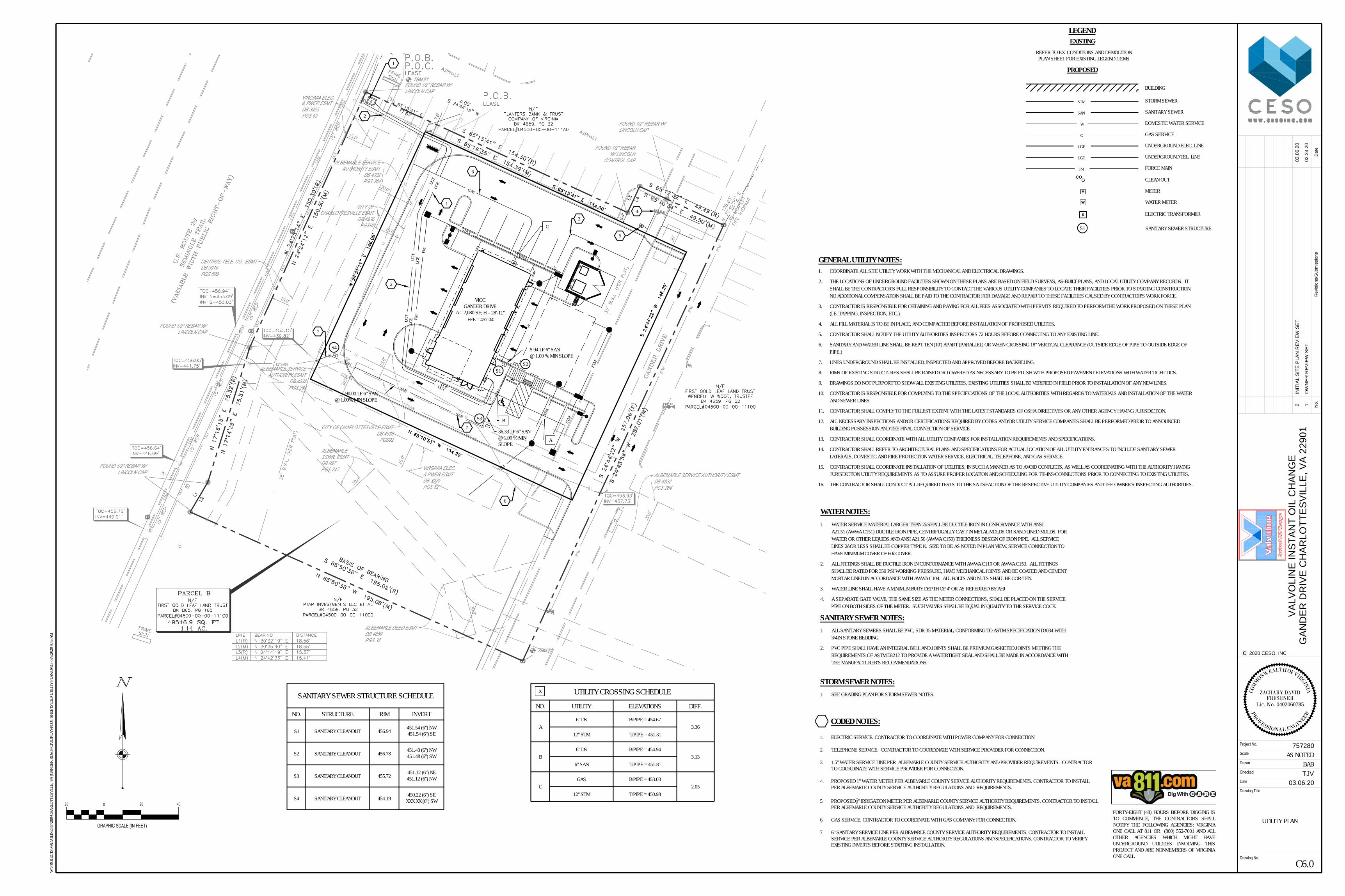
UGE
UGE
UGE
UGEUG
T
UGT
UGT
UGT
M
D
S
D
S
D
S
D
S
D
S
SAN
SAN
SAN
SAN COCO
GAS
E
FM
FM
STM
STM
STM
STM
STM
STM
CO
CO
VIOCGANDER DRIVE
A = 2,080 SF; H = 28'-11"
W
W
7.6'
STM
STM
STM
STM
STM
STM
STM
STM
G
G
G
G
GG
G
G
G
12''SAN
12''SAN
12''SAN
12''SAN
12''SAN
UGT
UGT
UGT
UGT
UGT
UGT
UGT
UGT
FOUND 1/2" REBAR W/LINCOLN CAP
FOUND 1/2" REBARW/ LINCOLN
CONTROL CAP
FOUND 1/2" REBAR W/LINCOLN CAP
FOUND 1/2" REBAR W/LINCOLN CAP
FOUND 1/2" REBAR W/LINCOLN CAP
10.0'
15.0'
15.0'
30.0'
15.0'
15.0'
20.0'
20.0'
20'
TBM #1
TBM #220
.0'
6.4'
20.0'
CITY OF CHARLOTTESVILLE ESMTDB 4936
PGS92
ALBEMARLE SERVICEAUTHORITY ESMT
DB 4332PGS 284
CITY OFCHARLOTTESVILLE ESMT
DB 4936PGS92
ALBEMARLE SERVICEAUTHORITY ESMT
DB 4332PGS 284
& PWER ESMTDB 3925PGS 52
CENTRAL TELE. CO. ESMTDB 3919PGS 699
ALBEMARLESSWR. ESMTDB 997PGS 747 VIRGINIA ELEC.
& PWER ESMTDB 3925PGS 52
ALBEMARLE DEED ESMTDB 4859PGS 32
ALBEMARLE SERVICE AUTHORITY ESMTDB 4332PGS 284
8''W
8''W
8''W
8''W
8''W
8''W
8''W
VIRGINIA ELEC. STORM SEWERSTM
SANITARY SEWERSAN
DOMESTIC WATER SERVICEW
GAS SERVICEG
UNDERGROUND ELEC. LINEUGE
UNDERGROUND TEL. LINEUGT
BUILDING
0
GRAPHIC SCALE (IN FEET)
20 20 40
CLEAN OUTCO
M
E
METER
ELECTRIC TRANSFORMER
GENERAL UTILITY NOTES:1. COORDINATE ALL SITE UTILITY WORK WITH THE MECHANICAL AND ELECTRICAL DRAWINGS.
2. THE LOCATIONS OF UNDERGROUND FACILITIES SHOWN ON THESE PLANS ARE BASED ON FIELD SURVEYS, AS-BUILT PLANS, AND LOCAL UTILITY COMPANY RECORDS. ITSHALL BE THE CONTRACTOR'S FULL RESPONSIBILITY TO CONTACT THE VARIOUS UTILITY COMPANIES TO LOCATE THEIR FACILITIES PRIOR TO STARTING CONSTRUCTION.NO ADDITIONAL COMPENSATION SHALL BE PAID TO THE CONTRACTOR FOR DAMAGE AND REPAIR TO THESE FACILITIES CAUSED BY CONTRACTOR'S WORK FORCE.
3. CONTRACTOR IS RESPONSIBLE FOR OBTAINING AND PAYING FOR ALL FEES ASSOCIATED WITH PERMITS REQUIRED TO PERFORM THE WORK PROPOSED ON THESE PLAN(I.E. TAPPING, INSPECTION, ETC.).
4. ALL FILL MATERIAL IS TO BE IN PLACE, AND COMPACTED BEFORE INSTALLATION OF PROPOSED UTILITIES.
5. CONTRACTOR SHALL NOTIFY THE UTILITY AUTHORITIES INSPECTORS 72 HOURS BEFORE CONNECTING TO ANY EXISTING LINE.
6. SANITARY AND WATER LINE SHALL BE KEPT TEN (10') APART (PARALLEL) OR WHEN CROSSING 18" VERTICAL CLEARANCE (OUTSIDE EDGE OF PIPE TO OUTSIDE EDGE OFPIPE.)
7. LINES UNDERGROUND SHALL BE INSTALLED, INSPECTED AND APPROVED BEFORE BACKFILLING.
8. RIMS OF EXISTING STRUCTURES SHALL BE RAISED OR LOWERED AS NECESSARY TO BE FLUSH WITH PROPOSED PAVEMENT ELEVATIONS WITH WATER TIGHT LIDS.
9. DRAWINGS DO NOT PURPORT TO SHOW ALL EXISTING UTILITIES. EXISTING UTILITIES SHALL BE VERIFIED IN FIELD PRIOR TO INSTALLATION OF ANY NEW LINES.
10. CONTRACTOR IS RESPONSIBLE FOR COMPLYING TO THE SPECIFICATIONS OF THE LOCAL AUTHORITIES WITH REGARDS TO MATERIALS AND INSTALLATION OF THE WATERAND SEWER LINES.
11. CONTRACTOR SHALL COMPLY TO THE FULLEST EXTENT WITH THE LATEST STANDARDS OF OSHA DIRECTIVES OR ANY OTHER AGENCY HAVING JURISDICTION.
12. ALL NECESSARY INSPECTIONS AND/OR CERTIFICATIONS REQUIRED BY CODES AND/OR UTILITY SERVICE COMPANIES SHALL BE PERFORMED PRIOR TO ANNOUNCEDBUILDING POSSESSION AND THE FINAL CONNECTION OF SERVICE.
13. CONTRACTOR SHALL COORDINATE WITH ALL UTILITY COMPANIES FOR INSTALLATION REQUIREMENTS AND SPECIFICATIONS.
14. CONTRACTOR SHALL REFER TO ARCHITECTURAL PLANS AND SPECIFICATIONS FOR ACTUAL LOCATION OF ALL UTILITY ENTRANCES TO INCLUDE SANITARY SEWERLATERALS, DOMESTIC AND FIRE PROTECTION WATER SERVICE, ELECTRICAL, TELEPHONE, AND GAS SERVICE.
15. CONTRACTOR SHALL COORDINATE INSTALLATION OF UTILITIES, IN SUCH A MANNER AS TO AVOID CONFLICTS, AS WELL AS COORDINATING WITH THE AUTHORITY HAVINGJURISDICTION UTILITY REQUIREMENTS AS TO ASSURE PROPER LOCATION AND SCHEDULING FOR TIE-INS/CONNECTIONS PRIOR TO CONNECTING TO EXISTING UTILITIES.
16. THE CONTRACTOR SHALL CONDUCT ALL REQUIRED TESTS TO THE SATISFACTION OF THE RESPECTIVE UTILITY COMPANIES AND THE OWNER'S INSPECTING AUTHORITIES.
WATER NOTES:1. WATER SERVICE MATERIAL LARGER THAN 2” SHALL BE DUCTILE IRON IN CONFORMANCE WITH ANSI
A21.51 (AWWA C151) DUCTILE IRON PIPE, CENTRIFUGALLY CAST IN METAL MOLDS OR SAND LINED MOLDS, FORWATER OR OTHER LIQUIDS AND ANSI A21.50 (AWWA C150) THICKNESS DESIGN OF IRON PIPE. ALL SERVICELINES 2” OR LESS SHALL BE COPPER TYPE K. SIZE TO BE AS NOTED IN PLAN VIEW. SERVICE CONNECTION TOHAVE MINIMUM COVER OF 60” COVER.
2. ALL FITTINGS SHALL BE DUCTILE IRON IN CONFORMANCE WITH AWWA C110 OR AWWA C153. ALL FITTINGSSHALL BE RATED FOR 350 PSI WORKING PRESSURE, HAVE MECHANICAL JOINTS AND BE COATED AND CEMENTMORTAR LINED IN ACCORDANCE WITH AWWA C104. ALL BOLTS AND NUTS SHALL BE COR-TEN.
3. WATER LINE SHALL HAVE A MINIMUM BURY DEPTH OF 4' OR AS REFERRED BY AHJ.
4. A SEPARATE GATE VALVE, THE SAME SIZE AS THE METER CONNECTIONS, SHALL BE PLACED ON THE SERVICEPIPE ON BOTH SIDES OF THE METER. SUCH VALVES SHALL BE EQUAL IN QUALITY TO THE SERVICE COCK.
SANITARY SEWER NOTES:1. ALL SANITARY SEWERS SHALL BE PVC, SDR 35 MATERIAL, CONFORMING TO ASTM SPECIFICATION D3034 WITH
3/4IN STONE BEDDING.
2. PVC PIPE SHALL HAVE AN INTEGRAL BELL AND JOINTS SHALL BE PREMIUM GASKETED JOINTS MEETING THEREQUIREMENTS OF ASTM D3212 TO PROVIDE A WATERTIGHT SEAL AND SHALL BE MADE IN ACCORDANCE WITHTHE MANUFACTURER'S RECOMMENDATIONS.
STORM SEWER NOTES:1. SEE GRADING PLAN FOR STORM SEWER NOTES.
WATER METER
1. ELECTRIC SERVICE. CONTRACTOR TO COORDINATE WITH POWER COMPANY FOR CONNECTION
2. TELEPHONE SERVICE. CONTRACTOR TO COORDINATE WITH SERVICE PROVIDER FOR CONNECTION.
3. 1.5" WATER SERVICE LINE PER ALBEMARLE COUNTY SERVICE AUTHORITY AND PROVIDER REQUIREMENTS. CONTRACTORTO COORDINATE WITH SERVICE PROVIDER FOR CONNECTION.
4. PROPOSED 1" WATER METER PER ALBEMARLE COUNTY SERVICE AUTHORITY REQUIREMENTS. CONTRACTOR TO INSTALLPER ALBEMARLE COUNTY SERVICE AUTHORITY REGULATIONS AND REQUIREMENTS.
5. PROPOSED 58" IRRIGATION METER PER ALBEMARLE COUNTY SERVICE AUTHORITY REQUIREMENTS. CONTRACTOR TO INSTALLPER ALBEMARLE COUNTY SERVICE AUTHORITY REGULATIONS AND REQUIREMENTS.
6. GAS SERVICE. CONTRACTOR TO COORDINATE WITH GAS COMPANY FOR CONNECTION.
7. 6" SANITARY SERVICE LINE PER ALBEMARLE COUNTY SERVICE AUTHORITY REQUIREMENTS. CONTRACTOR TO INSTALLSERVICE PER ALBEMARLE COUNTY SERVICE AUTHORITY REGULATIONS AND SPECIFICATIONS. CONTRACTOR TO VERIFYEXISTING INVERTS BEFORE STARTING INSTALLATION.
CODED NOTES:
UTILITY CROSSING SCHEDULE
NO. UTILITY ELEVATIONS DIFF.
A6" DS B/PIPE = 454.67
3.3612" STM T/PIPE = 451.31
B6" DS B/PIPE = 454.94
3.136" SAN T/PIPE = 451.81
CGAS B/PIPE = 453.03
2.0512" STM T/PIPE = 450.98
X
LEGENDEXISTING
PROPOSED
REFER TO EX. CONDITIONS AND DEMOLITIONPLAN SHEET FOR EXISTING LEGEND ITEMS
C6.0
UTILITY PLAN
BABAS NOTED
Date
Drawing No.
Project No.
Scale
Checked
Drawn
Drawing Title
2020 CESO, INCc
Da
te
No
.R
evisio
ns/S
ub
missio
ns
TJV
VA
LV
OL
IN
E IN
ST
AN
T O
IL
C
HA
NG
E
GA
ND
ER
D
RIV
E C
HA
RL
OT
TE
SV
IL
LE
, V
A 2
29
01
757280
03.06.20
02.24.20
OW
NE
R R
EV
IE
W S
ET
W:\P
ROJE
CTS\
VALV
OLIN
E\75
7280
-CHA
RLOT
TESV
ILLE,
VA
(GAN
DER
RD)\0
3-CI
VIL\P
LAN\
PLOT
SHE
ETS\
C6.0
UTILI
TY P
LAN.
DWG
- 3/6/
2020
9:45
AM
1
03.06.20
IN
IT
IA
L S
IT
E P
LA
N R
EV
IE
W S
ET
2
COM
M
ONWEALTH OF VIRGINIA
PR
OFESSIONAL ENGIN
EER
FRESHNERLic. No. 0402060785
ZACHARY DAVID
FORTY-EIGHT (48) HOURS BEFORE DIGGING ISTO COMMENCE, THE CONTRACTORS SHALLNOTIFY THE FOLLOWING AGENCIES: VIRGINIAONE CALL AT 811 OR (800) 552-7001 AND ALLOTHER AGENCIES WHICH MIGHT HAVEUNDERGROUND UTILITIES INVOLVING THISPROJECT AND ARE NONMEMBERS OF VIRGINIAONE CALL.
B
A
C
1
1
2
6
6
43
7
7
S1 SANITARY SEWER STRUCTURE
S3
S1S2
S4
SANITARY SEWER STRUCTURE SCHEDULE
NO. STRUCTURE RIM INVERT
S1 SANITARY CLEANOUT 456.94 451.54 (6") NW451.54 (6") SE
S2 SANITARY CLEANOUT 456.78 451.48 (6") NW451.48 (6") SW
S3 SANITARY CLEANOUT 455.72 451.12 (6") NE451.12 (6") NW
S4 SANITARY CLEANOUT 454.19 450.22 (6") SEXXX.XX (6") SW
FFE = 457.04'
FORCE MAINFM
5.94 LF 6" SAN@ 1.00 % MIN SLOPE
36.33 LF 6" SAN@ 1.00 % MINSLOPE
90.00 LF 6" SAN@ 1.00% MIN SLOPE
2
5
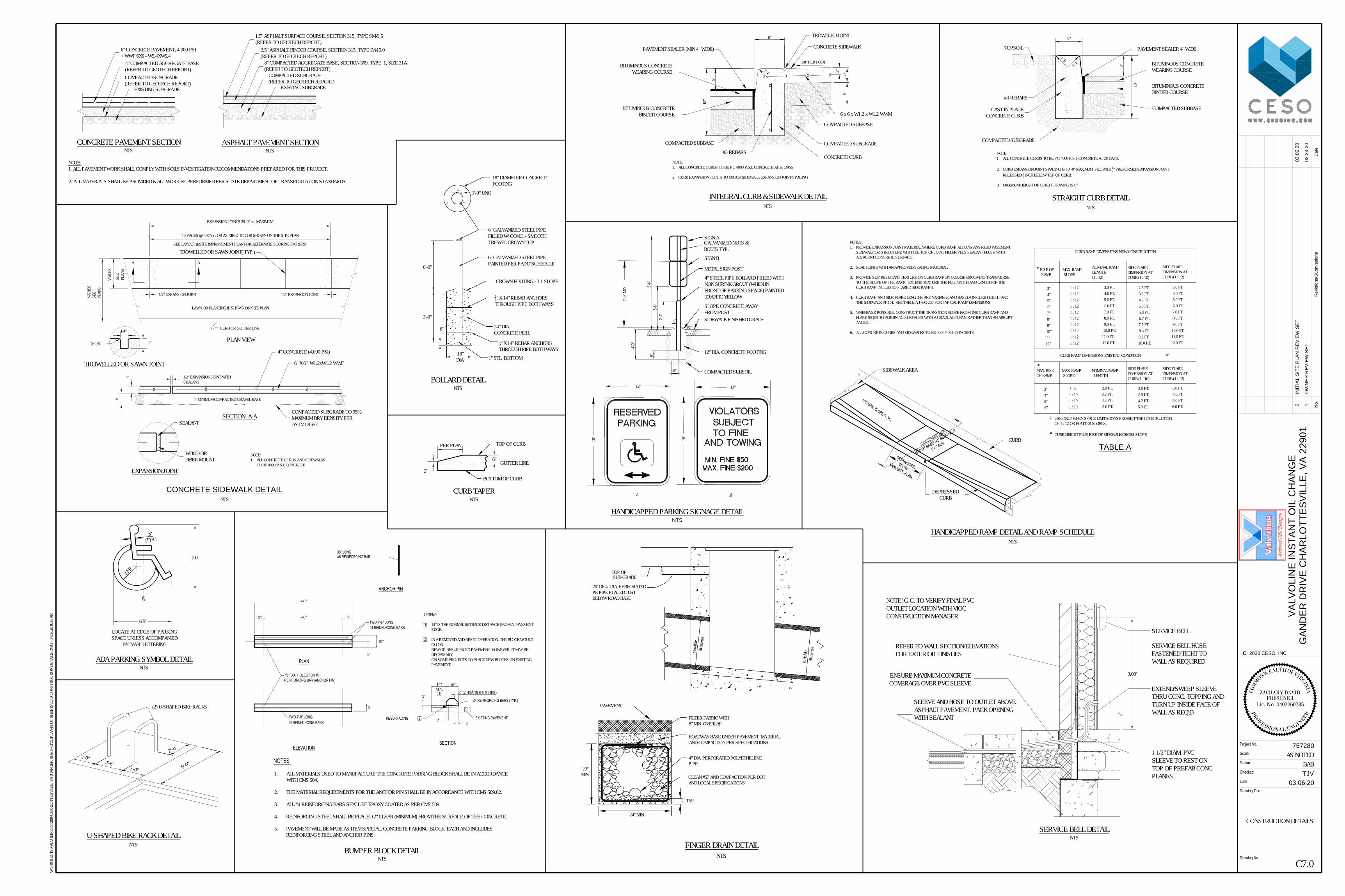
PAVEMENTdia
meter
varia
ble
20' OF 4" DIA. PERFORATEDPE PIPE PLACED JUSTBELOW ROAD BASE
TOP OFSUB-GRADE
varia
bledia
meter
CLEAN #57 AND COMPACTION PER DOTAND LOCAL SPECIFICATIONS
FILTER FABRIC WITH8" MIN. OVERLAP.
ROADWAY BASE UNDER PAVEMENT. MATERIALAND COMPACTION PER SPECIFICATIONS.
4" DIA. PERFORATED POLYETHELENEPIPE
20"MIN.
2" TYP.
24" MIN.
FINGER DRAIN DETAILNTS
X X X X X
NOTE:1. ALL CONCRETE CURBS AND SIDEWALKS
TO BE 4000 P.S.I. CONCRETE
EXPANSION JOINTS 20'-0" oc. MAXIMUM
4 SPACES @ 5'-0" oc. OR AS DIRECTED OR SHOWN ON THE SITE PLAN
SEE LAYOUT & SITE IMPROVEMENT PLAN FOR ALTERNATE SCORING PATTERN
1/2" EXPANSION JOINT
LAWN OR PLANTING IF SHOWN ON SITE PLAN
1/2" EXPANSION JOINT
AA
SEE
PLAN
S
VARI
ES
VARI
ESSE
EPL
ANS
CURB OR GUTTER LINE
PLAN VIEW1"
1/4"
R=1/8"
TROWELLED OR SAWN JOINT
4" 1/2" EXPANSION JOINT WITHSEALANT
4" MINIMUM COMPACTED GRAVEL BASE
SECTION A-A
4"
EXPANSION JOINT
CONCRETE SIDEWALK DETAIL
NTS
TROWELLED OR SAWN JOINT( TYP.)
6" X 6" W1.2xW1.2 WWF
COMPACTED SUBGRADE TO 95%MAXIMUM DRY DENSITY PERASTM D1557SEALANT
WOOD ORFIBER MOUNT
4" CONCRETE (4,000 PSI)
ASPHALT PAVEMENT SECTIONNTS
1.5" ASPHALT SURFACE COURSE, SECTION 315, TYPE SM-9.5(REFER TO GEOTECH REPORT)
2.5" ASPHALT BINDER COURSE, SECTION 315, TYPE IM-19.0(REFER TO GEOTECH REPORT)
8" COMPACTED AGGREGATE BASE, SECTION 309, TYPE 1, SIZE 21A(REFER TO GEOTECH REPORT)
EXISTING SUBGRADE
NOTE:1. ALL PAVEMENT WORK SHALL COMPLY WITH SOILS INVESTIGATION/RECOMMENDATIONS PREPARED FOR THIS PROJECT.
2. ALL MATERIALS SHALL BE PROVIDED & ALL WORK BE PERFORMED PER STATE DEPARTMENT OF TRANSPORTATION STANDARDS.
3'-0"
6'-0"
6"
6" GALVANIZED STEEL PIPEPAINTED PER PAINT SCHEDULE
24" DIA.CONCRETE PIER.
18"DIA.
BOLLARD DETAILNTS
6" GALVANIZED STEEL PIPEFILLED W/ CONC. - SMOOTHTROWEL CROWN TOP
1" STL. BOTTOM
CROWN FOOTING - 3:1 SLOPE
12" X 14" REBAR ANCHORSTHROUGH PIPE BOTH WAYS
18" DIAMETER CONCRETEFOOTING
1'-0" UNO
CONCRETE PAVEMENT SECTIONNTS
6" CONCRETE PAVEMENT, 4,000 PSI+ WWF 6X6 - W5.4XW5.4
4" COMPACTED AGGREGATE BASE(REFER TO GEOTECH REPORT)
EXISTING SUBGRADE
X X X X X X
NOTES:1. PROVIDE EXPANSION JOINT MATERIAL WHERE CURB RAMP ADJOINS ANY RIGID PAVEMENT,
SIDEWALK OR STRUCTURE WITH THE TOP OF JOINT FILLER PLUS SEALANT FLUSH WITHADJACENT CONCRETE SURFACE.
2. SEAL JOINTS WITH AN APPROVED SEALING MATERIAL.
3. PROVIDE SLIP RESISTANT TEXTURE ON CURB RAMP BY COARSE BROOMING TRANSVERSETO THE SLOPE OF THE RAMP. EXTEND TEXTURE THE FULL WIDTH AND LENGTH OF THECURB RAMP INCLUDING FLARED SIDE RAMPS.
4. CURB RAMP AND SIDE FLARE LENGTHS ARE VARIABLE AND BASED ON CURB HEIGHT ANDTHE SIDEWALK PITCH. SEE TABLE A J-8/C-207 FOR TYPICAL RAMP DIMENSIONS.
5. WHENEVER POSSIBLE, CONSTRUCT THE TRANSITION SLOPE FROM THE CURB RAMP ANDFLARE SIDES TO ADJOINING SURFACES WITH A GRADUAL CURVE RATHER THAN AN ABRUPTANGLE.
6. ALL CONCRETE CURBS AND SIDEWALKS TO BE 4000 P.S.I. CONCRETE
1:12 MAX. SLOPE (TYP.)
CROSS-SECTION
WIDTH SAME AS SIDEWALK
5'-0" MIN.
DEPRESSEDWIDTH
PER SITE PLAN
HANDICAPPED RAMP DETAIL AND RAMP SCHEDULENTS
1 : 101 : 10
1 : 121 : 12
1 : 121 : 12
1 : 121 : 12
1 : 121 : 121 : 12
CURB HEIGHT PLUS RISE OF SIDEWALK CROSS SLOPE
USE ONLY WHEN SPACE LIMITATIONS PROHIBIT THE CONSTRUCTIONOF 1 : 12 OR FLATTER SLOPES.
6.0 FT.5.0 FT.4.0 FT.3.0 FT.
5.0 FT.4.2 FT.3.3 FT.2.5 FT.
5.0 FT.4.2 FT.3.3 FT.2.0 FT.
1 : 101 : 8
6"5"4"3"
SIDE FLAREDIMENSION ATCURB (1 : 12)
SIDE FLAREDIMENSION ATCURB (1 : 10)
NOMINAL RAMP LENGTH
MAX. RAMP SLOPE
MAX. RISEOF RAMP
CURB RAMP DIMENSIONS EXISTING CONDITION
5.0 FT.4.2 FT.
8"
11.0 FT.12.0 FT.
10.0 FT.9.0 FT.8.0 FT.7.0 FT.6.0 FT.5.0 FT.4.0 FT.3.0 FT.
10.0 FT.9.2 FT.8.4 FT.7.5 FT.6.7 FT.5.8 FT.
3.3 FT.2.5 FT.
12.0 FT.11.0 FT.10.0 FT.9.0 FT.8.0 FT.7.0 FT.6.0 FT.5.0 FT.4.0 FT.3.0 FT.1 : 12
12"11"10"9"
7"6"5"4"3"
SIDE FLAREDIMENSION ATCURB (1 : 12)
SIDE FLAREDIMENSION ATCURB (1 : 10)
NOMINAL RAMPLENGTH(1 : 12)
MAX. RAMP SLOPE
RISE OF RAMP
CURB RAMP DIMENSIONS NEW CONSTRUCTION
TABLE A
SIDEWALK AREA
CURB
DEPRESSEDCURB
COMPACTED SUBGRADE(REFER TO GEOTECH REPORT)
COMPACTED SUBGRADE(REFER TO GEOTECH REPORT)
2'-0"2'-6"
2'-0" 6'-0"
(2) U-SHAPED BIKE RACKS
2''-0"
U-SHAPED BIKE RACK DETAILNTS
12" X 14" REBAR ANCHORSTHROUGH PIPE BOTH WAYS
1/2"4"
12"12"
18"
18"
5'-5"
8'-6"
2'-4"
6"
6"
7'-0"
MIN
A B
4'-0"
HANDICAPPED PARKING SIGNAGE DETAILNTS
SIGN AGALVANIZED NUTS &BOLTS TYP.SIGN B
METAL SIGN POST
4" STEEL PIPE BOLLARD FILLED WITHNON SHRINK GROUT (WHEN INFRONT OF PARKING SPACE) PAINTEDTRAFFIC YELLOW
SLOPE CONCRETE AWAYFROM POSTSIDEWALK FINISHED GRADE
12" DIA. CONCRETE FOOTING
COMPACTED SUBSOIL
8'-0"
6'-6"9" 9"
10"
5"
TWO 7'-8" LONG#4 REINFORCING BARS
30" LONG#6 REINFORCING BAR
7/8" DIA. HOLES FOR #6REINFORCING BAR (ANCHOR PIN)
TWO 7'-8" LONG#4 REINFORCING BARS
6"
3"
14"MIN.
10"
3" @ 45° (BOTH SIDES)
2"2"
EXISTING PAVEMENTRESURFACING 2
1#4 REINFORCING BARS (TYP.)
14" IS THE NORMAL SETBACK DISTANCE FROM A PAVEMENTEDGE.
IN A REMOVED AND RESET OPERATION, THE BLOCK WOULDGO ONNEW OR RESURFACED PAVEMENT. HOWEVER, IT MAY BENECESSARYON SOME PROJECTS TO PLACE NEW BLOCKS ON EXISTINGPAVEMENT.
1
2
ANCHOR PIN
PLAN
ELEVATIONSECTION
LEGEND:
1. ALL MATERIALS USED TO MANUFACTURE THE CONCRETE PARKING BLOCK SHALL BE IN ACCORDANCEWITH CMS 604.
2. THE MATERIAL REQUIREMENTS FOR THE ANCHOR PIN SHALL BE IN ACCORDANCE WITH CMS 509.02.
3. ALL #4 REINFORCING BARS SHALL BE EPOXY COATED AS PER CMS 509.
4. REINFORCING STEEL SHALL BE PLACED 2" CLEAR (MINIMUM) FROM THE SURFACE OF THE CONCRETE.
5. PAVEMENT WILL BE MADE AS ITEM SPECIAL, CONCRETE PARKING BLOCK, EACH AND INCLUDESREINFORCING STEEL AND ANCHOR PINS.
NOTES:
NTSBUMPER BLOCK DETAIL
6"
NOTE:1. ALL CONCRETE CURBS TO BE F'C 4000 P.S.I. CONCRETE AT 28 DAYS.
2. CURB EXPANSION JOINT SPACING IS 10"-0" MAXIMUM. FILL WITH 12" PREFORMED EXPANSION JOINTRECESSED 12 INCH BELOW TOP OF CURB.
3. MAXIMUM HEIGHT OF CURB TO PAVING IS 6".
6"
18"
1" R1" R
STRAIGHT CURB DETAILNTS
TOPSOIL PAVEMENT SEALER 4" WIDE
BITUMINOUS CONCRETEWEARING COURSE
BITUMINOUS CONCRETEBINDER COURSE
COMPACTED SUBBASE
COMPACTED SUBGRADE
CAST IN PLACECONCRETE CURB
#3 REBARS
8"4"
2"
18"
6"
6"
XXX X
1/8" PER FOOT
NOTE:1. ALL CONCRETE CURBS TO BE F'C 4000 P.S.I. CONCRETE AT 28 DAYS
2. CURB EXPANSION JOINTS TO MATCH SIDEWALK EXPANSION JOINT SPACING
1" R
INTEGRAL CURB & SIDEWALK DETAILNTS
PAVEMENT SEALER (MIN 4" WIDE)
BITUMINOUS CONCRETEWEARING COURSE
BITUMINOUS CONCRETEBINDER COURSE
TROWELED JOINT
CONCRETE SIDEWALK
COMPACTED SUBBASE
#3 REBARSCONCRETE CURB
COMPACTED SUBGRADE
COMPACTED SUBBASE
6 x 6 x W1.2 x W1.2 WWM
SERVICE BELL
SERVICE BELL HOSEFASTENED TIGHT TOWALL AS REQUIRED
1 1/2" DIAM. PVCSLEEVE TO REST ONTOP OF PREFAB CONC.PLANKS
EXTEND/SWEEP SLEEVETHRU CONC. TOPPING ANDTURN UP INSIDE FACE OFWALL AS REQ'D.
SLEEVE AND HOSE TO OUTLET ABOVEASPHALT PAVEMENT. PACK OPENINGWITH SEALANT
3.00'ENSURE MAXIMUM CONCRETECOVERAGE OVER PVC SLEEVE
REFER TO WALL SECTION/ELEVATIONSFOR EXTERIOR FINISHES
NOTE! G.C. TO VERIFY FINAL PVCOUTLET LOCATION WITH VIOCCONSTRUCTION MANAGER
SERVICE BELL DETAILNTS
ADA PARKING SYMBOL DETAILNTS
LOCATE AT EDGE OF PARKINGSPACE UNLESS ACCOMPANIED
BY "VAN" LETTERING
2.5'R
LC
6"(TYP.)
6.5'
7.0'
PER PLAN
6"
2"BOTTOM OF CURB
GUTTER LINE
TOP OF CURB
CURB TAPERNTS
C7.0
CONSTRUCTION DETAILS
BABAS NOTED
Date
Drawing No.
Project No.
Scale
Checked
Drawn
Drawing Title
2020 CESO, INCc
Da
te
No
.R
evisio
ns/S
ub
missio
ns
TJV
VA
LV
OL
IN
E IN
ST
AN
T O
IL
C
HA
NG
E
GA
ND
ER
D
RIV
E C
HA
RL
OT
TE
SV
IL
LE
, V
A 2
29
01
757280
03.06.20
02.24.20
OW
NE
R R
EV
IE
W S
ET
W:\P
ROJE
CTS\
VALV
OLIN
E\75
7280
-CHA
RLOT
TESV
ILLE,
VA
(GAN
DER
RD)\0
3-CI
VIL\P
LAN\
PLOT
SHE
ETS\
C7.0
CONS
TRUC
TION
DET
AILS
.DW
G - 3
/6/20
20 9:
45 A
M
1
03.06.20
IN
IT
IA
L S
IT
E P
LA
N R
EV
IE
W S
ET
2
COM
M
ONWEALTH OF VIRGINIA
PR
OFESSIONAL ENGIN
EER
FRESHNERLic. No. 0402060785
ZACHARY DAVID
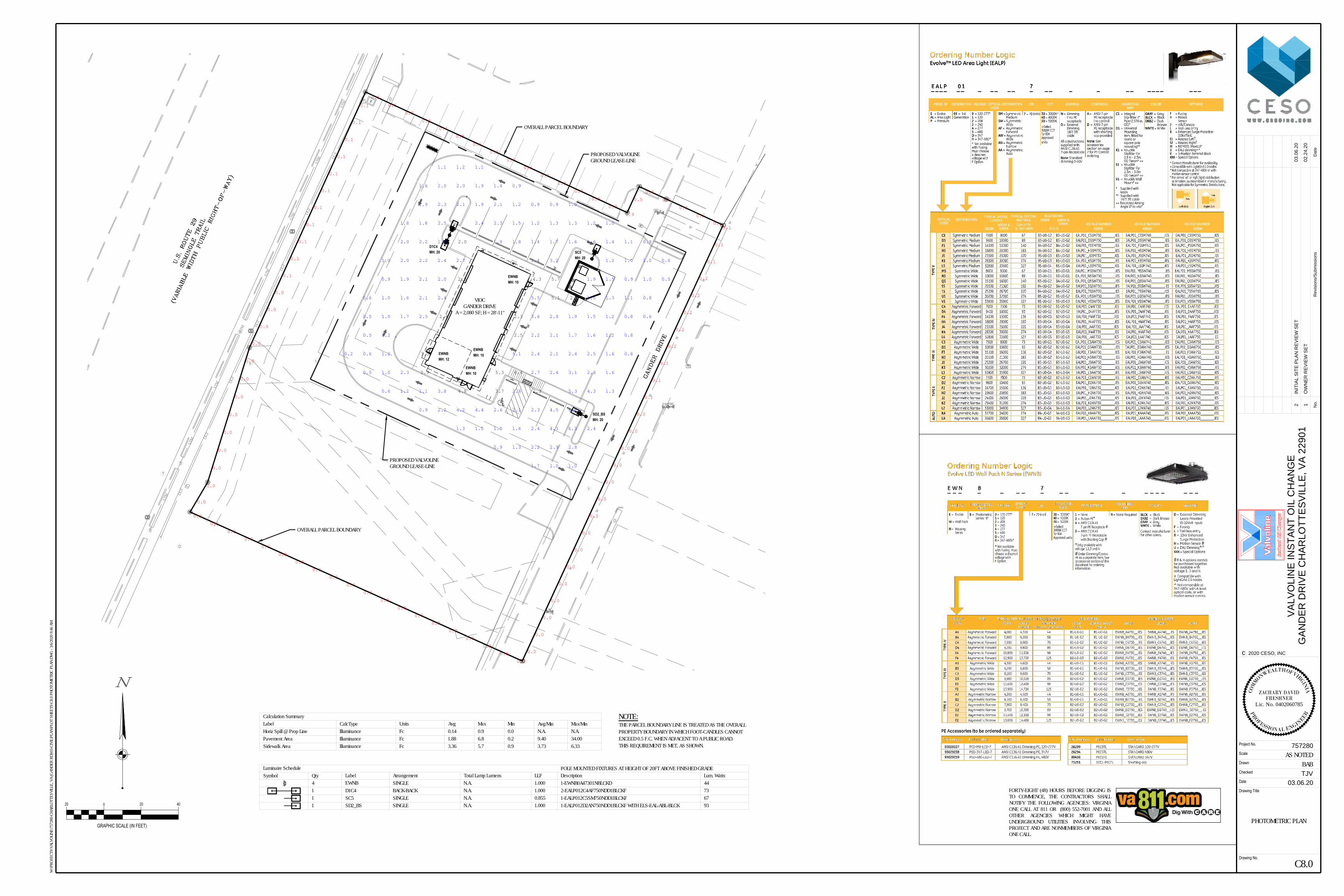
M
D
S
D
S
D
S
D
S
D
S
E
VIOCGANDER DRIVE
A = 2,080 SF; H = 28'-11"
W
W
STM
STM
STM
STM
STM
STM
STM
STM UG
T
UGT
UGT
UGT
UGT
UGT
UGT
UGT
W
W
W
W
W
W
W
W
W
EWNBMH: 10
EWNBMH: 10
EWNBMH: 10
EWNBMH: 12
D1C4MH: 20
SD2_BSMH: 20
SC5MH: 20
0.1
0.1
0.1
0.2
0.2
0.2
0.2
0.2
0.1
0.1
0.1
0.0
0.0
0.0
0.0
0.0
0.0
0.0
0.0
0.0
0.0
0.0
0.0
0.0
0.0
0.0
0.0
0.0
0.0
0.0
0.0
0.0
0.0
0.0
0.0
0.0
0.0
0.0
0.0
0.0
0.0
0.0
0.0
0.0
0.0
0.0
0.0
0.0
0.0
0.0
0.0
0.0
0.0
0.0
0.0
0.0
0.0
0.0
0.0
0.1
0.1
0.1
0.1
0.1
0.1
0.1
0.1
0.1
0.1
0.1
0.1
0.1
0.2
0.3
0.4
0.5
0.6
0.6
0.6
0.6
0.6
0.6
0.7
0.9
0.9
0.9
0.5
0.4
0.3
0.2
0.2
0.1
1.7 2.0 1.0
0.9 1.3 2.2 2.9 2.8
1.3 1.5 1.5 1.6 2.4 4.3 6.3 2.4
0.9 2.2 4.2 4.4 2.6 2.1 2.3 4.5 6.8
0.6 1.2 1.1 3.8 2.8 5.3 4.3 1.3
0.5 1.0 2.3 2.7 2.4 3.1 2.8 1.6
0.2 0.6 1.2 5.1 2.4 2.1 2.4 2.5 1.6 0.8
0.5 1.2 2.2 2.1 1.7 1.6 1.2 0.8
0.5 1.0 1.7 2.5 3.6 2.8 1.9 1.5 1.2 0.8 0.6
0.6 1.0 1.6 2.1 2.4 5.5 1.5 1.3 1.1 0.8
0.9 1.9 2.1 2.0 1.9 1.5 0.9 1.0 0.5
1.0 2.0 2.2 2.4 2.7 1.4 3.2 1.2 1.0 1.0 0.6
2.0 2.2 1.8 1.9 1.8 1.4 1.7 1.6 1.6 1.4 1.1 0.9
1.8 1.8 2.5 2.4 2.3 1.5 1.2 1.3 1.3 1.2 1.0
1.9 2.3 2.1 1.9 2.1 1.2 0.9 0.9 1.0
1.6 2.0 2.0 1.9 1.4 0.9
1.1 1.2 1.1
4.8 3.7 2.3
0.9 5.3 4.4
3.5
2.5
2.4 2.3
5.1 2.2
2.3 4.3 5.7
2.0
PROPOSED VALVOLINEGROUND LEASE-LINE
OVERALL PARCEL BOUNDARY
PROPOSED VALVOLINEGROUND LEASE-LINE
OVERALL PARCEL BOUNDARY
Luminaire ScheduleSymbol Qty Label Arrangement Total Lamp Lumens LLF Description Lum. Watts
4 EWNB SINGLE N.A. 1.000 1-EWNB0A47301NBLCKD 44
1 SC5 SINGLE N.A. 0.855 1-EALP012C5SM750NDD1BLCKF 671 SD2_BS SINGLE N.A. 1.000 1-EALP012D2AN750NDD1BLCKF WITH ELS-EAL-ABL-BLCK 93
Calculation SummaryLabel CalcType Units Avg Max Min Avg/Min Max/MinHoriz Spill @ Prop Line Illuminance Fc 0.14 0.9 0.0 N.A. N.A.Pavement Area Illuminance Fc 1.88 6.8 0.2 9.40 34.00Sidewalk Area Illuminance Fc 3.36 5.7 0.9 3.73 6.33
1 D1C4 BACK-BACK N.A. 1.000 2-EALP012C4AF750NDD1BLCKF 73
0
GRAPHIC SCALE (IN FEET)
20 20 40
C8.0
PHOTOMETRIC PLAN
BABAS NOTED
Date
Drawing No.
Project No.
Scale
Checked
Drawn
Drawing Title
2020 CESO, INCc
Da
te
No
.R
evisio
ns/S
ub
missio
ns
TJV
VA
LV
OL
IN
E IN
ST
AN
T O
IL
C
HA
NG
E
GA
ND
ER
D
RIV
E C
HA
RL
OT
TE
SV
IL
LE
, V
A 2
29
01
757280
03.06.20
02.24.20
OW
NE
R R
EV
IE
W S
ET
W:\P
ROJE
CTS\
VALV
OLIN
E\75
7280
-CHA
RLOT
TESV
ILLE,
VA
(GAN
DER
RD)\0
3-CI
VIL\P
LAN\
PLOT
SHE
ETS\
C8.0
PHOT
OMET
RIC
PLAN
.DW
G - 3
/6/20
20 9:
46 A
M
1
03.06.20
IN
IT
IA
L S
IT
E P
LA
N R
EV
IE
W S
ET
2
COM
M
ONWEALTH OF VIRGINIA
PR
OFESSIONAL ENGIN
EER
FRESHNERLic. No. 0402060785
ZACHARY DAVID
FORTY-EIGHT (48) HOURS BEFORE DIGGING ISTO COMMENCE, THE CONTRACTORS SHALLNOTIFY THE FOLLOWING AGENCIES: VIRGINIAONE CALL AT 811 OR (800) 552-7001 AND ALLOTHER AGENCIES WHICH MIGHT HAVEUNDERGROUND UTILITIES INVOLVING THISPROJECT AND ARE NONMEMBERS OF VIRGINIAONE CALL.
POLE MOUNTED FIXTURES AT HEIGHT OF 20FT ABOVE FINISHED GRADE
NOTE:THE PARCEL BOUNDARY LINE IS TREATED AS THE OVERALLPROPERTY BOUNDARY IN WHICH FOOT-CANDLES CANNOTEXCEED 0.5 F.C. WHEN ADJACENT TO A PUBLIC ROAD.THIS REQUIREMENT IS MET, AS SHOWN.


SCALE:
2
EXTERIOR ELEVATION
OVERALL FRONT
1/4" = 1'-0"
OPEN
T.O. TOWER
+/-28'-11" A.F.F.
B.O. SOFFIT
+/-23'-4" A.F.F.
B.O. SOFFIT
+/-13'-5" A.F.F.
T.O. SILL
+4'-0" A.F.F.
T.O. SLAB
0'-0" A.F.F.
CONT. RIDGE VENT
E.I.F.S. 1 (TYP.)
LOGO SIGN (600)
E.I.F.S. SILL
ALUM. GUTTER,
FASCIA & D.S. (TYP.)
METAL AWNING
SNOW GUARDS
PROVIDE 6" TALL
VINYL ADDRESS
NUMBERS AS REQ'D
LED SIGN (602)
BRICK WAINSCOT
ALUM. STOREFRONT
ASPHALT SHINGLES
(SEE EXT. FINISH NOTES
AND ROOF PLAN)
SECURITY CAMERA.
SEE SECURITY PLAN
E.I.F.S. 1 (TYP.)
EQ
.E
Q.
1
A3.1
NOTE: CENTER SIGN ON ROOF
PEAK & AWNING BELOW. FIELD
VERIFY ALL CONDITIONS
RIDGE HEIGHT
+/-22'-7" A.F.F.
BRICK WAINSCOT
B.O. SOFFIT
+/-13'-5" A.F.F.
T.O. SLAB
0'-0" A.F.F.
ALUM. GUTTER, FASCIA
& DOWNSPOUTS
T.O. SILL
+4'-0" A.F.F.
CONT. PRECAST
CONC. SILL
10
'-6
"
@ E
NT
RY
11
'-6
"
@ E
NT
RY
E.I.F.S. 1 (TYP.)
WALL MOUNTED
LIGHT (TYP.)
13
'-0
" T
YP
.
CA
ME
RA
H
T.
1'-8"
SCALE:
1
EXTERIOR ELEVATION
OVERALL RIGHT
1/4" = 1'-0"
7'-1
0"
(T
YP
.)
2
A3.1
10
'-4
"
(T
YP
.)
M
A6.1
B.O. SOFFIT
+/-13'-5" A.F.F.
T.O. SLAB
0'-0" A.F.F.
T.O. SILL
+4'-0" A.F.F.
T.O. TOWER
+/-28'-11" A.F.F.
B.O. SOFFIT
+/-23'-4" A.F.F.
B.O. SOFFIT
+/-13'-5" A.F.F.
T.O. SILL
+4'-0" A.F.F.
T.O. SLAB
0'-0" A.F.F.
EQ
.E
Q.
OPEN
CONT. PRECAST
CONC. SILL
SECURITY CAMERA.
(SEE SECURITY PLAN)
E.I.F.S. 1 (TYP.)
BRICK WAINSCOT
ALUM. GUTTER,
FASCIA & D.S. (TYP.)
EXHAUST VENT CAP
(SEE MECHANICAL)
VTR - VERIFY QUANITY &
LOCATIONS (SEE PLUMBING)
ACCESS PANEL, CONT. SEALANT
AROUND ENTIRE FRAME WHERE
FLANGE MEETS MASONRY
SNOW GUARDS
E.I.F.S 1 SILL
E.I.F.S. 1 (TYP.)
METAL AWNING
BRICK WAINSCOT
E.I.F.S. 1 (TYP.)
NOTE: CENTER SIGN ON
ROOF PEAK & AWNING
BELOW. FIELD VERIFY
ALL CONDITIONS
WALL MOUNTED
LIGHT (TYP.)LED SIGN (602)
LOGO SIGN (600)
13
'-0
" T
YP
.
CA
ME
RA
H
T.
1'-8"
HOSE BIB
REF PLUMBING
4. ALL FLASHING, RIDGE CAPS, DRIP EDGE ETC. SHALL MATCH
GUTTER & DOWNSPOUT MANUFACTURER'S STANDARD DETAILS.
PROVIDE VENTED RIDGE CAP WHERE SHOWN.
5. EXHAUST FAN, VTRS & SIMILAR ITEMS ON ROOF SHALL BE
PAINTED TO MATCH ROOF.
1. EIFS SHALL BE DRYVIT, CLASS PB DRAINAGE SYSTEM WITH FLUID
APPLIED WATER RESISTIVE BARRIER BEHIND INSULATION BOARD.
2. SIGNAGE SHOWN ON THESE ELEVATIONS IS FOR GENERAL
REFERENCE PURPOSES ONLY. ALL SIGNAGE SHALL BE APPLIED
FOR & PERMITTED UNDER A SEPARATE SIGNAGE SUBMITTAL.
3. G.C. SHALL PROVIDE BLOCKING IN STUD WALL BEHIND EACH SIGN
AS REQUIRED BY SIGN VENDOR - FIELD VERIFY REQUIREMENTS W/
VENDOR & OWNER'S REPRESENTATIVE.
NUMBER
600
DESCRIPTION SIZE ILLUMINATEDQUANTITY
LOGO SIGN 7'-8" X 5'-11" (45 S.F.) INTERNALLY
601 LANE INDICATOR SIGN 10'-0" X 1'-4" (13.33 S.F.) NO
602 OPEN SIGN 2'-7 1/2" X 11 1/2" (2.52 S.F.) INTERNALLY
603 MONUMENT SIGN 6'-6" X 6'-9" (44 S.F.) INTERNALLY
604 LOGO SIGN 4'-11" X 6'-5" (31 S.F.) INTERNALLY
PER LOCAL AND DEVELOPMENTAL RESTRICTIONS
2
3
2
1
1
PROVIDED BY OWNER, INSTALLED BY G.C.
PROVIDED BY OWNER, INSTALLED BY SIGN CONTRACTOR
PROVIDED BY OWNER, INSTALLED BY SIGN CONTRACTOR
EXTERIOR INSULATED DRYVIT (SANDPEBBLE FINE)
FINISH SYSTEM : COLOR: E.I.F.S. 1 = #113 AMARILLO WHITE
ROOF SHINGLES: OWENS CORNING DURATION SERIES "DRIFTWOOD"
PRECAST SILL: CUSTOM CAST STONE - "LIGHT BUFF" (REFER TO SILL PROFILE)
MORTAR: LEHIGH - "LIGHT BEIGE"
MASONRY SEALER: ALL MASONRY SURFACES SHALL BE TREATED W/SEALER
REFER TO SPECIFICATIONS.
STANDING SEAM FIRESTONE UNA-CLAD KYNAR 500 / HYLAR METAL 5000
AWNING: FLUOROCARBON STEEL "CHAMPAGNE METALLIC"
UNDERSIDE & FRAME TO BE PAINTED SW 6152 "SUPERIOR BRONZE"
BRICK WAINSCOT: BELDEN - "MODULAR MIDLAND BLEND A"
(GRADE TO PRECAST SILL)
GUTTER, DOWNSPOUTS, BERRIDGE - "SIERRA TAN"
FASCIA & EXPOSED TRIM:
STOREFRONT SYSTEM: 2x4 1/2" KAWNEER TRIFAB VG 451T SERIES CLEAR ANODIZED
ALUMINUM STOREFRONT SYSTEM W/1" INSULATED GLAZING.
H.M. DOORS & FRAMES: FIELD PAINT w/SHERWIN-WILLIAMS B66-310 PRO-CYRL
PRIMER FOLLOWED BY (2) FINISH COATS OF B66-300
SHER-CYRL HPA. COLOR SHALL BE SW-7515 "HOMESTEAD
BROWN". PROVIDE MOCK-UP AND VERIFY COLOR W/OWNER.
O.H. DOOR FINISH: CLEAR ANODIZED ALUMINUM
PARKING LOT STRIPING: SHERWIN-WILLIAMS #TM226 SETFAST TM PAINT.
COLOR SHALL BE "WHITE".
HANDICAP STALL STRIPING: SHERWIN-WILLIAMS #TM2133 SETFAST TM PAINT.
COLOR SHALL BE "ADA BLUE".
MISC. ROOF VENTS, PAINT TO MATCH SW7046 "ANONYMOUS"
FANS, ETC.
Date
Drawing No.
Project No.
Scale
Checked
Drawn
Drawing Title
2020 CESO, INCc
Da
te
No
.R
evisio
ns/S
ub
missio
ns
ELM
VA
LV
OL
IN
E IN
ST
AN
T O
IL
C
HA
NG
E
GA
ND
ER
D
RIV
E C
HA
RL
OT
TE
SV
IL
LE
, V
A 2
29
01
757280-01
02.19.20
OW
NE
R R
EV
IE
W02.19.20
175 MONTROSE WEST AVE., SUITE 400, AKRON, OH 44321
PHONE: (330) 665-0660 FAX: (888) 208-4826
PE
RM
IT
S
ET
03.09.20
\\cesoinc.local\root\data\P
RO
JE
CT
S\V
ALV
OLIN
E\757280-C
HA
RLO
TT
ES
VILLE
, V
A (G
AN
DE
R R
D)\02-B
LD
G\P
LA
N\D
WG
\3B
RH
-S
TnD
A
rchC
AD
2020 Q
1\3B
RH
-S
TnD
A
3 E
xterior E
levations, 3/6/2020 11:32:58
AM
, R
IC
HA
RD
CESO
AS NOTED
A-3a
EXTERIOR
ELEVATIONS

RADIANT HEATER VENT -
SEE MECHANICAL DRAWINGS
(FIELD VERIFY LOCATIONS)
CONT. PRECAST
CONC. SILL
PROTECTION BOLLARDS ENCROACH ON
DOORS BY 1" (TYP.) - SEE DETAIL 6/A10
WALL MOUNTED
LIGHT
LOGO SIGN (604)
CENTER ON TOWER
7'-1
0"
(T
YP
.)
SCALE:
4
EXTERIOR ELEVATION
OVERALL REAR
1/4" = 1'-0"
CONT. RIDGE VENT
ASPHALT SHINGLES
(SEE EXT. FINISH NOTES
AND ROOF PLAN)
LANE INDICATOR
SIGNS (601) TYP.
E.I.F.S. 1 (TYP.)
RIDGE HEIGHT
+/-22'-7" A.F.F.
BRICK WAINSCOT
B.O. SOFFIT
+/-13'-5" A.F.F.
T.O. SLAB
0'-0" A.F.F.
T.O. SILL
+4'-0" A.F.F.
VTR - VERIFY QUANITY &
LOCATIONS (SEE PLUMBING)
ALUM. GUTTER,
FASCIA & D.S. (TYP.)
SECURITY CAMERA.
SEE SECURITY PLAN
WALL MOUNTED
LIGHTS
7'-6
" T
O
B.O
. S
IG
N
HVAC/ELECT. EQUIP. SHOWN
FOR REFERENCE ONLY
RAKE FLASHING
@ WALL BEYOND
T.O. TOWER
+/-28'-11" A.F.F.
B.O. SOFFIT
+/-23'-4" A.F.F.
B.O. SOFFIT
+/-13'-5" A.F.F.
T.O. SILL
+4'-0" A.F.F.
T.O. SLAB
0'-0" A.F.F.
E.I.F.S. 1 (TYP.)
ALUM. GUTTER,
FASCIA & D.S. (TYP.)
METAL AWNING
SNOW GUARDS
SECURITY CAMERA
(SEE SECURITY PLAN)
BRICK WAINSCOT
E.I.F.S. 1 (TYP.)
10
'-4
"
(T
YP
.)
13
'-0
" T
YP
.
CA
ME
RA
H
T.
1'-8" 1'-8"1'-8"
4
A3.1
EXHAUST VENT CAP
(SEE MECHANICAL)
SCALE:
3
EXTERIOR ELEVATION
OVERALL LEFT
1/4" = 1'-0"
T.O. TOWER
+/-28'-11" A.F.F.
B.O. SOFFIT
+/-23'-4" A.F.F.
B.O. SOFFIT
+/-13'-5" A.F.F.
T.O. SILL
+4'-0" A.F.F.
T.O. SLAB
0'-0" A.F.F.
SNOW GUARDS
RIDGE HEIGHT
+/-22'-7" A.F.F.
B.O. SOFFIT
+/-13'-5" A.F.F.
T.O. SLAB
0'-0" A.F.F.
T.O. SILL
+4'-0" A.F.F.
ACCESS PANEL, CONT. SEALANT AROUND ENTIRE
FRAME WHERE FLANGE MEETS MASONRY
E.I.F.S. 1 (TYP.)
METAL AWNING
BRICK WAINSCOT
E.I.F.S. 1 (TYP.)
BRICK WAINSCOT
E.I.F.S. 1 (TYP.)
3
A3.1
ALUM. GUTTER,
FASCIA & D.S. (TYP.)
CONT. PRECAST
CONC. SILL
RAKE FLASHING
@ WALL BEYOND
EXHAUST VENT CAP
(SEE MECHANICAL)
VTR - VERIFY QUANITY
& LOCATIONS
(SEE PLUMBING)
SECURITY CAMERA.
SEE SECURITY PLAN
13
'-0
" T
YP
.
CA
ME
RA
H
T.
1'-8"
HOSE BIB
REF PLUMBING
GAS METER
REF PLUMBING
4. ALL FLASHING, RIDGE CAPS, DRIP EDGE ETC. SHALL MATCH
GUTTER & DOWNSPOUT MANUFACTURER'S STANDARD DETAILS.
PROVIDE VENTED RIDGE CAP WHERE SHOWN.
5. EXHAUST FAN, VTRS & SIMILAR ITEMS ON ROOF SHALL BE
PAINTED TO MATCH ROOF.
1. EIFS SHALL BE DRYVIT, CLASS PB DRAINAGE SYSTEM WITH FLUID
APPLIED WATER RESISTIVE BARRIER BEHIND INSULATION BOARD.
2. SIGNAGE SHOWN ON THESE ELEVATIONS IS FOR GENERAL
REFERENCE PURPOSES ONLY. ALL SIGNAGE SHALL BE APPLIED
FOR & PERMITTED UNDER A SEPARATE SIGNAGE SUBMITTAL.
3. G.C. SHALL PROVIDE BLOCKING IN STUD WALL BEHIND EACH SIGN
AS REQUIRED BY SIGN VENDOR - FIELD VERIFY REQUIREMENTS W/
VENDOR & OWNER'S REPRESENTATIVE.
NUMBER
600
DESCRIPTION SIZE ILLUMINATEDQUANTITY
LOGO SIGN 7'-8" X 5'-11" (45 S.F.) INTERNALLY
601 LANE INDICATOR SIGN 10'-0" X 1'-4" (13.33 S.F.) NO
602 OPEN SIGN 2'-7 1/2" X 11 1/2" (2.52 S.F.) INTERNALLY
603 MONUMENT SIGN 6'-6" X 6'-9" (44 S.F.) INTERNALLY
604 LOGO SIGN 4'-11" X 6'-5" (31 S.F.) INTERNALLY
PER LOCAL AND DEVELOPMENTAL RESTRICTIONS
2
3
2
1
1
PROVIDED BY OWNER, INSTALLED BY G.C.
PROVIDED BY OWNER, INSTALLED BY SIGN CONTRACTOR
PROVIDED BY OWNER, INSTALLED BY SIGN CONTRACTOR
EXTERIOR INSULATED DRYVIT (SANDPEBBLE FINE)
FINISH SYSTEM : COLOR: E.I.F.S. 1 = #113 AMARILLO WHITE
ROOF SHINGLES: OWENS CORNING DURATION SERIES "DRIFTWOOD"
PRECAST SILL: CUSTOM CAST STONE - "LIGHT BUFF" (REFER TO SILL PROFILE)
MORTAR: LEHIGH - "LIGHT BEIGE"
MASONRY SEALER: ALL MASONRY SURFACES SHALL BE TREATED W/SEALER
REFER TO SPECIFICATIONS.
STANDING SEAM FIRESTONE UNA-CLAD KYNAR 500 / HYLAR METAL 5000
AWNING: FLUOROCARBON STEEL "CHAMPAGNE METALLIC"
UNDERSIDE & FRAME TO BE PAINTED SW 6152 "SUPERIOR BRONZE"
BRICK WAINSCOT: BELDEN - "MODULAR MIDLAND BLEND A"
(GRADE TO PRECAST SILL)
GUTTER, DOWNSPOUTS, BERRIDGE - "SIERRA TAN"
FASCIA & EXPOSED TRIM:
STOREFRONT SYSTEM: 2x4 1/2" KAWNEER TRIFAB VG 451T SERIES CLEAR ANODIZED
ALUMINUM STOREFRONT SYSTEM W/1" INSULATED GLAZING.
H.M. DOORS & FRAMES: FIELD PAINT w/SHERWIN-WILLIAMS B66-310 PRO-CYRL
PRIMER FOLLOWED BY (2) FINISH COATS OF B66-300
SHER-CYRL HPA. COLOR SHALL BE SW-7515 "HOMESTEAD
BROWN". PROVIDE MOCK-UP AND VERIFY COLOR W/OWNER.
O.H. DOOR FINISH: CLEAR ANODIZED ALUMINUM
PARKING LOT STRIPING: SHERWIN-WILLIAMS #TM226 SETFAST TM PAINT.
COLOR SHALL BE "WHITE".
HANDICAP STALL STRIPING: SHERWIN-WILLIAMS #TM2133 SETFAST TM PAINT.
COLOR SHALL BE "ADA BLUE".
MISC. ROOF VENTS, PAINT TO MATCH SW7046 "ANONYMOUS"
FANS, ETC.
Date
Drawing No.
Project No.
Scale
Checked
Drawn
Drawing Title
2020 CESO, INCc
Da
te
No
.R
evisio
ns/S
ub
missio
ns
ELM
VA
LV
OL
IN
E IN
ST
AN
T O
IL
C
HA
NG
E
GA
ND
ER
D
RIV
E C
HA
RL
OT
TE
SV
IL
LE
, V
A 2
29
01
757280-01
02.19.20
OW
NE
R R
EV
IE
W02.19.20
175 MONTROSE WEST AVE., SUITE 400, AKRON, OH 44321
PHONE: (330) 665-0660 FAX: (888) 208-4826
PE
RM
IT
S
ET
03.09.20
\\cesoinc.local\root\data\P
RO
JE
CT
S\V
ALV
OLIN
E\757280-C
HA
RLO
TT
ES
VILLE
, V
A (G
AN
DE
R R
D)\02-B
LD
G\P
LA
N\D
WG
\3B
RH
-S
TnD
A
rchC
AD
2020 Q
1\3B
RH
-S
TnD
A
3 E
xterior E
levations, 3/6/2020 11:33:16
AM
, R
IC
HA
RD
CESO
AS NOTED
A-3b
EXTERIOR
ELEVATIONS
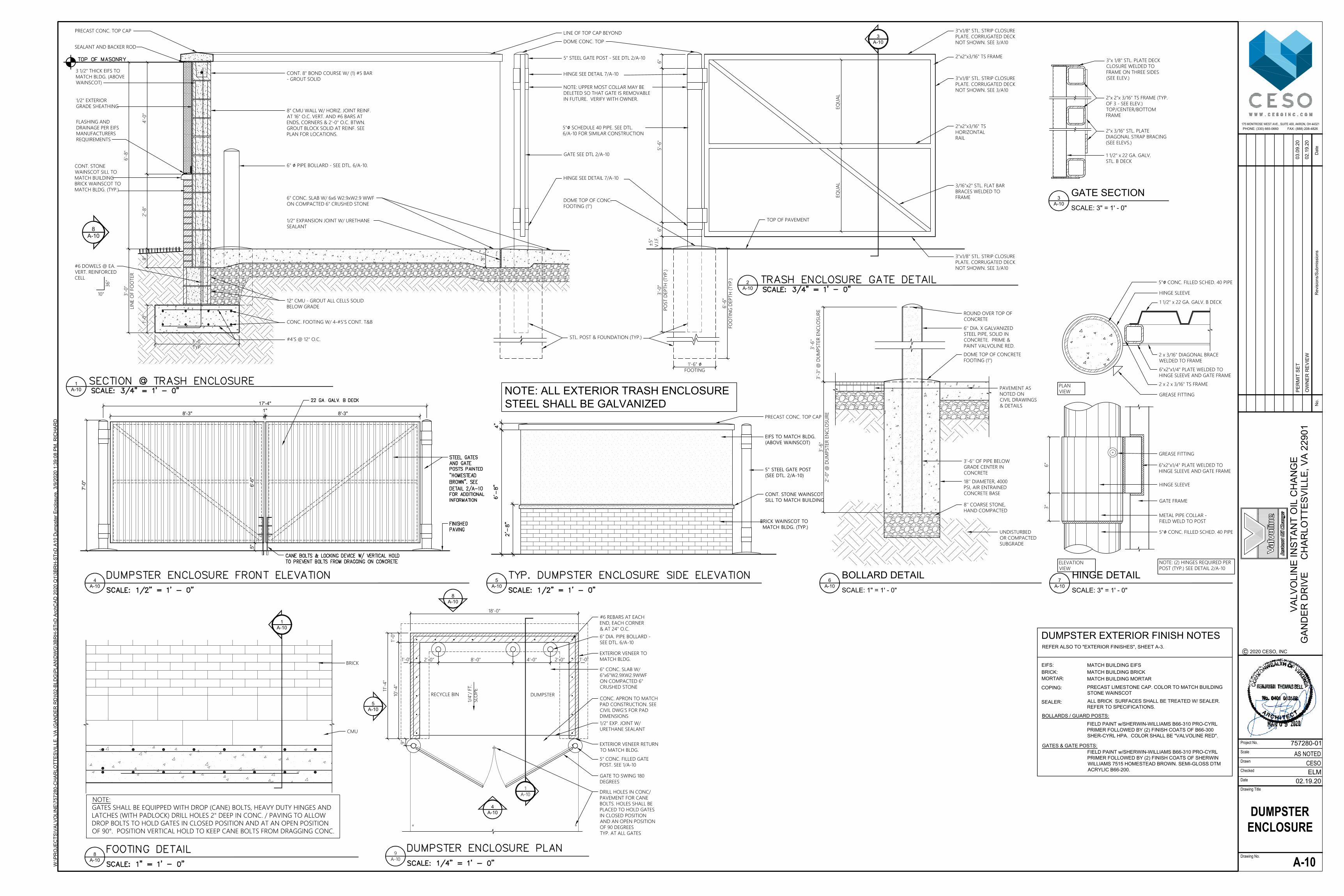
17'-4"
7'-0
"
4
A-10
6'-6
"5
"
8'-3" 8'-3"
1"
5" STEEL GATE POST
(SEE DTL. 2/A-10)
CONT. STONE WAINSCOT
SILL TO MATCH BUILDING
PRECAST CONC. TOP CAP
5
A-10
EIFS TO MATCH BLDG.
(ABOVE WAINSCOT)
BRICK WAINSCOT TO
MATCH BLDG. (TYP.)
NOTE: ALL EXTERIOR TRASH ENCLOSURE
STEEL SHALL BE GALVANIZED
18'-0"
1'-0"
10'-4"
11'-4"
9"
2'-0"1'-0"
8'-0" 4'-0" 2'-0"1'-0"
RECYCLE BINDUMPSTER
1/4"/ FT.
SLO
PE
#6 REBARS AT EACH
END, EACH CORNER
& AT 24" O.C.
6" DIA. PIPE BOLLARD -
SEE DTL. 6/A-10
6" CONC. SLAB W/
6"x6"W2.9XW2.9WWF
ON COMPACTED 6"
CRUSHED STONE
1/2" EXP. JOINT W/
URETHANE SEALANT
CONC. APRON TO MATCH
PAD CONSTRUCTION. SEE
CIVIL DWG'S FOR PAD
DIMENSIONS
5" CONC. FILLED GATE
POST. SEE 1/A-10
GATE TO SWING 180
DEGREES
DRILL HOLES IN CONC/
PAVEMENT FOR CANE
BOLTS. HOLES SHALL BE
PLACED TO HOLD GATES
IN CLOSED POSITION
AND AN OPEN POSITION
OF 90 DEGREES
TYP. AT ALL GATES
5
A-10
8
A-10
4
A-10
1
A-10
9
A-10
EXTERIOR VENEER TO
MATCH BLDG.
EXTERIOR VENEER RETURN
TO MATCH BLDG.
8"
2'-8"
4'-0"
6'-8"
3'-0"
LIN
E O
F FO
OTER
8"
1
A-10
8
A-10
±5"
V.I.F.
6"
5'-6"
6"
2
A-10
3
A-10
TOP OF PAVEMENT
EQ
UA
LEQ
UA
L
3'-0"
TYP.
1'-0"
36"
10"
6" ∅ PIPE BOLLARD - SEE DTL. 6/A-10.
PRECAST CONC. TOP CAP
#6 DOWELS @ EA.
VERT. REINFORCED
CELL
#4'S @ 12" O.C.
CONC. FOOTING W/ 4-#5'S CONT. T&B
12" CMU - GROUT ALL CELLS SOLID
BELOW GRADE
8" CMU WALL W/ HORIZ. JOINT REINF.
AT 16" O.C. VERT. AND #6 BARS AT
ENDS, CORNERS & 2'-0" O.C. BTWN.
GROUT BLOCK SOLID AT REINF. SEE
PLAN FOR LOCATIONS.
CONT. 8" BOND COURSE W/ (1) #5 BAR
- GROUT SOLID
6" CONC. SLAB W/ 6x6 W2.9xW2.9 WWF
ON COMPACTED 6" CRUSHED STONE
1/2" EXPANSION JOINT W/ URETHANE
SEALANT
DOME TOP OF CONC.
FOOTING (1")
HINGE SEE DETAIL 7/A-10
5"∅ SCHEDULE 40 PIPE. SEE DTL.
6/A-10 FOR SIMILAR CONSTRUCTION
GATE SEE DTL 2/A-10
NOTE: UPPER MOST COLLAR MAY BE
DELETED SO THAT GATE IS REMOVABLE
IN FUTURE. VERIFY WITH OWNER.
HINGE SEE DETAIL 7/A-10
5" STEEL GATE POST - SEE DTL 2/A-10
DOME CONC. TOP
LINE OF TOP CAP BEYOND
SEALANT AND BACKER ROD
3/16"x2" STL. FLAT BAR
BRACES WELDED TO
FRAME
2"x2"x3/16" TS
HORIZONTAL
RAIL
2"x2"x3/16" TS FRAME
3"x1/8" STL. STRIP CLOSURE
PLATE. CORRUGATED DECK
NOT SHOWN. SEE 3/A10
3"x1/8" STL. STRIP CLOSURE
PLATE. CORRUGATED DECK
NOT SHOWN. SEE 3/A10
3"x1/8" STL. STRIP CLOSURE
PLATE. CORRUGATED DECK
NOT SHOWN. SEE 3/A10
3 1/2" THICK EIFS TO
MATCH BLDG. (ABOVE
WAINSCOT)
BRICK WAINSCOT TO
MATCH BLDG. (TYP.)
1/2" EXTERIOR
GRADE SHEATHING
FLASHING AND
DRAINAGE PER EIFS
MANUFACTURERS
REQUIREMENTS
CONT. STONE
WAINSCOT SILL TO
MATCH BUILDING
6'-6"
FO
OTIN
G D
EP
TH
(TYP
.)
1'-6" ∅FOOTING
3'-0"
PO
ST D
EP
TH
(TYP
.)
STL. POST & FOUNDATION (TYP.)
DOME TOP OF CONCRETE
FOOTING (1")
3'-6"
2'-0" @
D
UM
PSTER
EN
CLO
SU
RE
6'' DIA. X GALVANIZED
STEEL PIPE, SOLID IN
CONCRETE. PRIME &
PAINT VALVOLINE RED.
ROUND OVER TOP OF
CONCRETE
UNDISTURBED
OR COMPACTED
SUBGRADE
8'' COARSE STONE,
HAND COMPACTED
18'' DIAMETER, 4000
PSI, AIR ENTRAINED
CONCRETE BASE
3'-6'' OF PIPE BELOW
GRADE CENTER IN
CONCRETE
PAVEMENT AS
NOTED ON
CIVIL DRAWINGS
& DETAILS
6
A-10
BOLLARD DETAIL
SCALE: 1" = 1' - 0"
3'-6''
3'-3" @
D
UM
PSTER
EN
CLO
SU
RE
1
A-10
CMU
8
A-10
NOTE:
GATES SHALL BE EQUIPPED WITH DROP (CANE) BOLTS, HEAVY DUTY HINGES AND
LATCHES (WITH PADLOCK) DRILL HOLES 2" DEEP IN CONC. / PAVING TO ALLOW
DROP BOLTS TO HOLD GATES IN CLOSED POSITION AND AT AN OPEN POSITION
OF 90°. POSITION VERTICAL HOLD TO KEEP CANE BOLTS FROM DRAGGING CONC.
BRICK
3
A-10
GATE SECTION
SCALE: 3" = 1' - 0"
1 1/2" x 22 GA. GALV.
STL. B DECK
3"x 1/8" STL. PLATE DECK
CLOSURE WELDED TO
FRAME ON THREE SIDES
(SEE ELEV.)
2"x 3/16" STL. PLATE
DIAGONAL STRAP BRACING
(SEE ELEVS.)
2"x 2"x 3/16" TS FRAME (TYP.
OF 3 - SEE ELEV.)
TOP/CENTER/BOTTOM
FRAME
7
A-10
HINGE DETAIL
SCALE: 3" = 1' - 0"
GREASE FITTING
2 x 2 x 3/16" TS FRAME
1 1/2" x 22 GA. GALV. B DECK
HINGE SLEEVE
5"∅ CONC. FILLED SCHED. 40 PIPE
6"x2"x1/4" PLATE WELDED TO
HINGE SLEEVE AND GATE FRAME
2 x 3/16" DIAGONAL BRACE
WELDED TO FRAME
3"
6"
6"x2"x1/4" PLATE WELDED TO
HINGE SLEEVE AND GATE FRAME
HINGE SLEEVE
METAL PIPE COLLAR -
FIELD WELD TO POST
GREASE FITTING
GATE FRAME
5"∅ CONC. FILLED SCHED. 40 PIPE
NOTE: (2) HINGES REQUIRED PER
POST (TYP.) SEE DETAIL 2/A-10
PLAN
VIEW
ELEVATION
VIEW
Date
Drawing No.
Project No.
Scale
Checked
Drawn
Drawing Title
2020 CESO, INCc
Da
te
No
.R
evisio
ns/S
ub
missio
ns
ELM
VA
LV
OL
IN
E IN
ST
AN
T O
IL
C
HA
NG
E
GA
ND
ER
D
RIV
E C
HA
RL
OT
TE
SV
IL
LE
, V
A 2
29
01
757280-01
02.19.20
OW
NE
R R
EV
IE
W02.19.20
175 MONTROSE WEST AVE., SUITE 400, AKRON, OH 44321
PHONE: (330) 665-0660 FAX: (888) 208-4826
PE
RM
IT
S
ET
03.09.20
W:\P
RO
JE
CT
S\V
ALV
OLIN
E\757280-C
HA
RLO
TT
ES
VILLE
, V
A (G
AN
DE
R R
D)\02-B
LD
G\P
LA
N\D
WG
\3B
RH
-S
TnD
A
rchC
AD
2020 Q
1\3B
RH
-S
TnD
A
10 D
um
pster E
nclosure, 3/9/2020 1:39:08 P
M, R
IC
HA
RD
CESO
AS NOTED
A-10
DUMPSTER
ENCLOSURE
FIELD PAINT w/SHERWIN-WILLIAMS B66-310 PRO-CYRL
PRIMER FOLLOWED BY (2) FINISH COATS OF B66-300
SHER-CYRL HPA. COLOR SHALL BE "VALVOLINE RED".
FIELD PAINT w/SHERWIN-WILLIAMS B66-310 PRO-CYRL
PRIMER FOLLOWED BY (2) FINISH COATS OF SHERWIN
WILLIAMS 7515 HOMESTEAD BROWN. SEMI-GLOSS DTM
ACRYLIC B66-200.
MATCH BUILDING BRICK
MATCH BUILDING MORTAR
ALL SURFACES SHALL BE TREATED W/ SEALER.
REFER TO SPECIFICATIONS.
REFER ALSO TO "EXTERIOR FINISHES", SHEET A-3.
PRECAST LIMESTONE CAP. COLOR TO MATCH BUILDING
STONE WAINSCOT
BRICK:
MORTAR:
BOLLARDS / GUARD POSTS:
GATES & GATE POSTS:
DUMPSTER EXTERIOR FINISH NOTES
MATCH BUILDING EIFS
COPING:
SEALER:
EIFS:
BRICK