
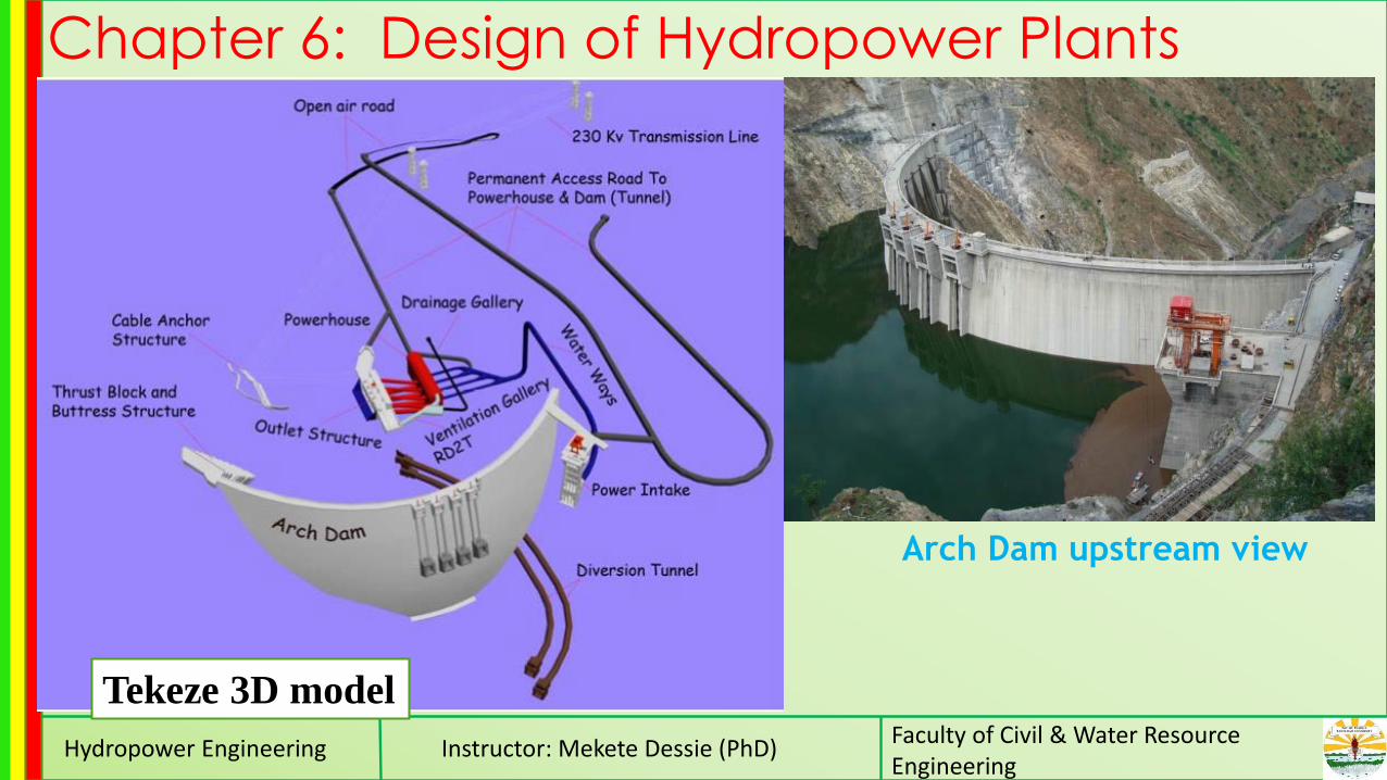
Arch Dam upstream view - ndl.ethernet.edu.et
51
Hydropower Engineering Instructor: Mekete Dessie (PhD) Faculty of Civil & Water Resource Engineering Chapter 6: Design of Hydropower Plants Tekeze 3D model Arch Dam upstream view
Transcript of Arch Dam upstream view - ndl.ethernet.edu.et
Hydropower Engineering Instructor: Mekete Dessie (PhD)Faculty of Civil & Water Resource Engineering
Chapter 6: Design of Hydropower Plants
Tekeze 3D model
Arch Dam upstream view

Hydropower Engineering Instructor: Mekete Dessie (PhD)Faculty of Civil & Water Resource Engineering
Design of Civil Structures (cont.) Water Hammer Analysis and Surge Tank Design

Hydropower Engineering Instructor: Mekete Dessie (PhD)Faculty of Civil & Water Resource Engineering
Introduction
Water Hammer
• Water hammer is a phenomenon of pressure change in closed pipes caused when
flowing water in a pipeline is rapidly decelerated or accelerated
• The phenomenon is accompanied by a series of positive and negative pressure waves
which travel back and forth in the pipe system until they are damped out by friction
• When a valve in a pipe or penstock carrying water is closed, the pressure head
immediately upstream of the valve is increased and a pulse of high pressure is
propagated upstream to the nearest open water surface
• On the downstream side of the valve a lowered pressure moves in a downstream
direction to the nearest open water surface

Hydropower Engineering Instructor: Mekete Dessie (PhD)Faculty of Civil & Water Resource Engineering
Causes of rapid changes in flow
(acceleration/deceleration):
Sudden opening or closing of control valves
Starting or stopping of pumps
Rejecting or accepting load by hydraulic turbine
There are two theories in analyzing water hammer:
Elastic water column (EWC) theory
Rigid water column (RWC) theory
• When the time it takes a valve to close is long
compared to the propagation time for a pressure wave
to travel the length of the pipe, then the rigid column
theory is appropriate;
• otherwise considering elastic water column theory is
necessary.Rapid valve closure followed by pressure
increase, pipe walls expand , liquid
compression ; and transient conditions
propagate upstream
Steady state prior to valve closure

Hydropower Engineering Instructor: Mekete Dessie (PhD)Faculty of Civil & Water Resource Engineering
The maximum water hammer pressure

Hydropower Engineering Instructor: Mekete Dessie (PhD)Faculty of Civil & Water Resource Engineering
Conservation of linear momentum
The maximum water hammer pressure (cont.)

Hydropower Engineering Instructor: Mekete Dessie (PhD)Faculty of Civil & Water Resource Engineering
The maximum water hammer pressure (cont.)
Hydropower Engineering Instructor: Mekete Dessie (PhD)Faculty of Civil & Water Resource Engineering
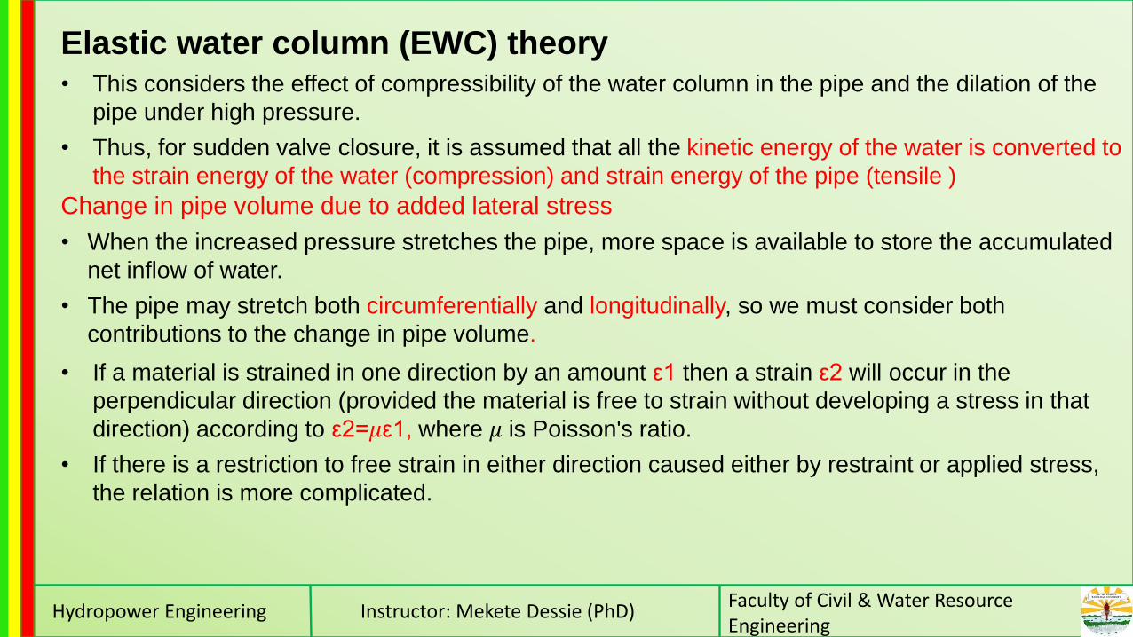
Elastic water column (EWC) theory• This considers the effect of compressibility of the water column in the pipe and the dilation of the
pipe under high pressure.
• Thus, for sudden valve closure, it is assumed that all the kinetic energy of the water is converted to
the strain energy of the water (compression) and strain energy of the pipe (tensile )
• If a material is strained in one direction by an amount ε1 then a strain ε2 will occur in the
perpendicular direction (provided the material is free to strain without developing a stress in that
direction) according to ε2=𝜇ε1, where 𝜇 is Poisson's ratio.
• If there is a restriction to free strain in either direction caused either by restraint or applied stress,
the relation is more complicated.
Change in pipe volume due to added lateral stress
• When the increased pressure stretches the pipe, more space is available to store the accumulated
net inflow of water.
• The pipe may stretch both circumferentially and longitudinally, so we must consider both
contributions to the change in pipe volume.

Hydropower Engineering Instructor: Mekete Dessie (PhD)Faculty of Civil & Water Resource Engineering
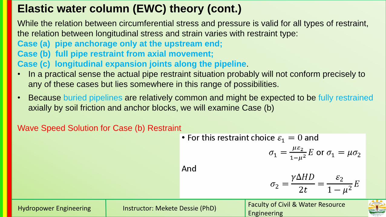
Elastic water column (EWC) theory (cont.)
Hydropower Engineering Instructor: Mekete Dessie (PhD)Faculty of Civil & Water Resource Engineering
While the relation between circumferential stress and pressure is valid for all types of restraint,
the relation between longitudinal stress and strain varies with restraint type:
Case (a) pipe anchorage only at the upstream end;
Case (b) full pipe restraint from axial movement;
Case (c) longitudinal expansion joints along the pipeline.
• In a practical sense the actual pipe restraint situation probably will not conform precisely to
any of these cases but lies somewhere in this range of possibilities.
Elastic water column (EWC) theory (cont.)
• Because buried pipelines are relatively common and might be expected to be fully restrained
axially by soil friction and anchor blocks, we will examine Case (b)
Wave Speed Solution for Case (b) Restraint

Hydropower Engineering Instructor: Mekete Dessie (PhD)Faculty of Civil & Water Resource Engineering
Elastic water column (EWC) theory (cont.)
Reduction in the volume of water within the pipe is based on compressibility of water

Hydropower Engineering Instructor: Mekete Dessie (PhD)Faculty of Civil & Water Resource Engineering
Elastic water column (EWC) theory (cont.)
Wylie and Streeter (1993) show that the equation
for wave speed can be conveniently expressed in
the general form:

Hydropower Engineering Instructor: Mekete Dessie (PhD)Faculty of Civil & Water Resource Engineering
Elastic water column (EWC) theory (cont.)

Hydropower Engineering Instructor: Mekete Dessie (PhD)Faculty of Civil & Water Resource Engineering
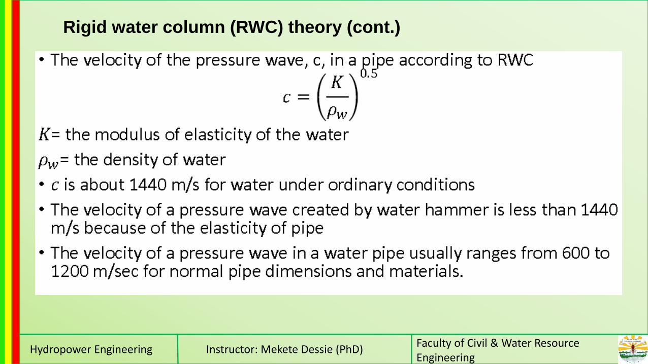
Rigid water column (RWC) theory• As the water flows to the reservoir it creates
partial vacuum conditions and the pressure
in the pipe swings in the –ve direction.
• This induces the reservoir water to flow in to
the pipe.
• But the valve being partially closed, much of
this water again retarded giving rise to a +ve
swing pressure again.
• Thus a valve closure brings about pressure
oscillations.
• On the other hand, the velocity past the gate
at any instant is given by:

Hydropower Engineering Instructor: Mekete Dessie (PhD)Faculty of Civil & Water Resource Engineering
Rigid water column (RWC) theory (cont.)
Hydropower Engineering Instructor: Mekete Dessie (PhD)Faculty of Civil & Water Resource Engineering
Rigid water column (RWC) theory (cont.)

Hydropower Engineering Instructor: Mekete Dessie (PhD)Faculty of Civil & Water Resource Engineering
Rigid water column (RWC) theory (cont.)

Hydropower Engineering Instructor: Mekete Dessie (PhD)Faculty of Civil & Water Resource Engineering
Example

Hydropower Engineering Instructor: Mekete Dessie (PhD)Faculty of Civil & Water Resource Engineering
Solution
For fully strained in the axial case,
C=1-η2
η=0, Hence C=1
Hydropower Engineering Instructor: Mekete Dessie (PhD)Faculty of Civil & Water Resource Engineering
Surge Tanks• The surge tank, also called the expansion chamber, is a structure which forms an
essential part of the pressure conduit conveyance system whenever such system is long.
• Their primary purpose is protection of low pressure tunnel in medium and high –head
plants against high water hammer pressure arising from sudden rejection or acceptance
of load.
• The surge thank converts these high frequency, high pressure transients (water hammer)
in to low frequency low pressure, mass oscillation.
Uses • It shortens the distance between the turbine inlet and the nearest free water surface, and
thereby greatly reduces the intensity of the water hammer waves.
• With a reduction of turbine load, the water level in the chamber rises until it exceeds the level
in the main reservoir, thus retarding the main conduit flow and absorbing the surplus kinetic
energy.
• In case of increase of turbine load, the surge tank acts as a reservoir which provides
sufficient water to enable the turbine to pick up their new load safely and quickly and to keep
them running at the increased load until the water level in the surge chamber has fallen
below its original level.

Hydropower Engineering Instructor: Mekete Dessie (PhD)Faculty of Civil & Water Resource Engineering
•The surge tank is located between the almost horizontal or slightly inclined conduit and
steeply sloping penstock and is designed as a chamber excavated in the mountain.
Types of Surge TanksLocation relative to terrain
• underground surge tank
• over ground surge tank
Location in the hydraulic system
• Upstream surge tank (u/s to the power house ) on
the headrace tunnel
• Downstream surge tank on the tailrace tunnel
Hydraulic functioning & cross-sectional shape
• Simple surge tanks
• Restricted orifice (or throttled) surge tanks
• Differential surge tanks
• Surge tanks with expansion chambers and others

Hydropower Engineering Instructor: Mekete Dessie (PhD)Faculty of Civil & Water Resource Engineering

Hydropower Engineering Instructor: Mekete Dessie (PhD)Faculty of Civil & Water Resource Engineering
Design Consideration of Surge Tank The surge chambers are designed to meet the following conditions:
• The surge chamber must be so located that pressure variations caused by water
hammer are kept within acceptable limits.
• The chamber must be stable, i.e. the surges resulting from small partial load changes
must be naturally damped and must not under any condition be continued or amplified.
• The chamber must be of such size and so proportioned that it will contain the
maximum possible upsurge (unless a spillway is provided).
• The lowest down surge will not allow air to be drawn into the tunnel.
• The range of surges must not be great enough to cause undesirably heavy governor
movements or difficulty in startup load.
It is usual to consider full-load rejection under two conditions:
• With the reservoir at its maximum level, in which case the maximum upsurge
level will govern the top level of the chamber;
• With the reservoir at its lowest draw down, in which case the first down surge
level may control the bottom level of the chamber if air drawing is to be
avoided.

Hydropower Engineering Instructor: Mekete Dessie (PhD)Faculty of Civil & Water Resource Engineering
Hydraulic design of simple surge tank
Hydropower Engineering Instructor: Mekete Dessie (PhD)Faculty of Civil & Water Resource Engineering
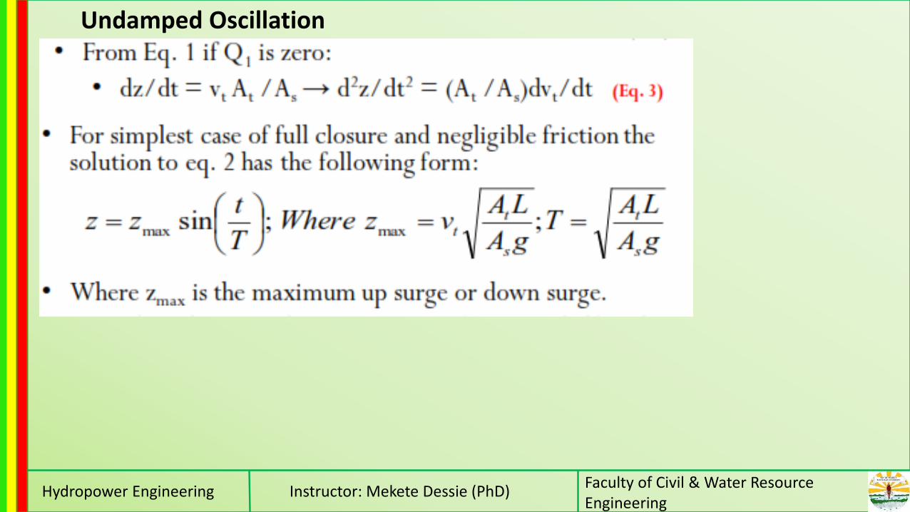
Undamped Oscillation

Hydropower Engineering Instructor: Mekete Dessie (PhD)Faculty of Civil & Water Resource Engineering

Hydropower Engineering Instructor: Mekete Dessie (PhD)Faculty of Civil & Water Resource Engineering
Cross-sectional Area (Stability Consideration)
• Characteristic oscillation in the surge tank damped by hydraulic friction in the conduits.
• The required cross-sectional area of a surge tank is determined based on stability
considerations for the surge oscillations in the tank. Stability conditions of the surge
system were established by Thoma.
• He stated that in order to prevent the development of unstable oscillations the cross-
section of the surge tank should exceed a certain critical magnitude.

Hydropower Engineering Instructor: Mekete Dessie (PhD)Faculty of Civil & Water Resource Engineering
Cross-sectional Area (cont.)
Hydropower Engineering Instructor: Mekete Dessie (PhD)Faculty of Civil & Water Resource Engineering
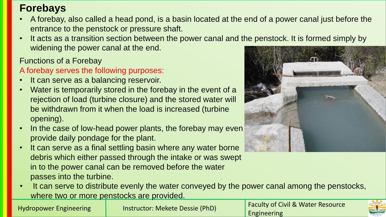
Forebays• A forebay, also called a head pond, is a basin located at the end of a power canal just before the
entrance to the penstock or pressure shaft.
• It acts as a transition section between the power canal and the penstock. It is formed simply by widening the power canal at the end.
Functions of a Forebay
A forebay serves the following purposes:
• It can serve as a balancing reservoir.
• Water is temporarily stored in the forebay in the event of a
rejection of load (turbine closure) and the stored water will
be withdrawn from it when the load is increased (turbine
opening).
• In the case of low-head power plants, the forebay may even
provide daily pondage for the plant.
• It can serve as a final settling basin where any water borne
debris which either passed through the intake or was swept
in to the power canal can be removed before the water
passes into the turbine.• It can serve to distribute evenly the water conveyed by the power canal among the penstocks,
where two or more penstocks are provided.

Hydropower Engineering Instructor: Mekete Dessie (PhD)Faculty of Civil & Water Resource Engineering
Components of a Forebay
• The basin: used to store water and sediment (if any)
• The spillway (sometimes of the siphon type), with the overflow weir: used to dispose
excess water that might enter the forebay
• The bottom outlet which is generally flushing sluice gate for sediment and for de-
watering the forebay and the power
• The penstock inlet: serves in controlling
flow into the pressure conduit and in
preventing floating debris from entering
the conduit. It also provides smooth
transition between the basin and the
conduit.
Hydropower Engineering Instructor: Mekete Dessie (PhD)Faculty of Civil & Water Resource Engineering
Design guidelines for a forebay• The location of the forebay is primarily governed by topographic conditions and the geology of
the site.
• The site of both the forebay and the powerhouse should be selected simultaneously with a
view of ensuring the shortest possible penstocks/pressure shafts.
• The entire basin of the forebay may be either excavated in rock or constructed above the
terrain, enclosed by embankments and retaining walls.
• The size of a forebay vary depending on the sediment content of the water conveyed in the
power canal and whether it is to serve for storage.
• A gradual transition section should be provided between the power canal and the forebay basin.
In the case of wide forebay, baffle piers are usually constructed at the basin inlet in order to
ensure even distribution of flow to the basin.
• The bottom of the forebay basin should be provided with a proper slope to enable periodical
flushing of the silt deposited.
• A bottom lining of the forebay basin is required in soils where large seepage is expected. The
smoothed bottom of the basin is covered with plastic clay having thickness of 20 to 50 cm. The
cover is compacted in several layers and is protected against disturbance due to soaking and
wave action by a layer of gravel or crushed stone.

Hydropower Engineering Instructor: Mekete Dessie (PhD)Faculty of Civil & Water Resource Engineering
Design guidelines for a forebay contd.• The spillway is usually an ogee type with stilling basin. If the discharge to be taken
care of is great and if, at the same time, prevailing conditions do not permit the
construction of a long overflow weir, water surface regulation within narrow limits can
be attained by constructing a siphon type spillway.
• The spillway and the bottom outlet canal should be combined immediately at the foot
of the basin. Water spilling over the spillway crest and through the bottom outlet can
be either diverted into a suitable river bed (if any) in a nearby side valley or conveyed
by a special chute.
• It is important to keep the entrance to the penstock fully submerged.
• The usual components of the intake such as trash racks, flow control devices (gates
or valves), etc. must be provided at the penstock inlet.
• It is necessary to install an air vent behind the gate to prevent damage to the
penstock if for some reason the penstock entrance is blocked or the gate is suddenly
closed causing a low pressure inside the conduit. The air vent can also help remove
air from inside the penstock during startup.

Hydropower Engineering Instructor: Mekete Dessie (PhD)Faculty of Civil & Water Resource Engineering
PENSTOCK• The penstock is high pressure pipeline between
forebay (surge tank or reservoirs ) and the turbine.
• The design principle of penstocks are the same as
that of pressure vessels & tanks but water hammer
effect has to be considered.
• For short length, a separate penstock for each
turbine is preferable. For a moderate heads & long
distances a single penstock is used to find two or
more turbines through a special branching pipe
called Manifold.
Classification of penstockClassification may based on:
• The material of construction
• Method of support
• Rigidity of connection and support
• Number of penstocks
Gibe II

Hydropower Engineering Instructor: Mekete Dessie (PhD)Faculty of Civil & Water Resource Engineering
Material of construction• Factors for the choice of material are: head, topography & discharge.
• Materials used are steel, R.C., asbestos cement, PVC, wood stave pipes, banded steel,
etc.
Factors which have to be considered when deciding which material to use for a particular
project:
• Operating pressure
• Diameter and friction loss
• Weight and ease of installation
• Accessibility of site
• Cost of the penstock
• Design life
• Availability
• Weather conditions

Hydropower Engineering Instructor: Mekete Dessie (PhD)Faculty of Civil & Water Resource Engineering
Material of construction contd.Steel penstocks: the most common type of installation, due to simplicity in fabrication, strength,
and assurance that they will perform in a wide variety of circumstances. Normal practice is to use
welded steel pipe sections.
Cast-in-place or precast reinforced concrete pipe: Very large diameters are somewhat
impractical. Cast-in place concrete pipes are usually Limited to Heads of less than 35 m.
•According to Creagerand Justin (1950), these penstocks can be used up to 4m in diameter and
under heads up to 185 m by using a welded steel shell embedded in the reinforced concrete
Fiberglass and polyvinyl chloride (PVC) plastic pipe : A penstock at the Niagara Mohawk
plant uses a fiberglass pipe 3 m in diameter.
Wood stave pipes have been used in diameters ranging from 15 cm up to 6 m and utilized at
heads up to 185 m with proper design.

Hydropower Engineering Instructor: Mekete Dessie (PhD)Faculty of Civil & Water Resource Engineering
Method of supportA penstock may be either buried or embodied underground ( or inside dams) or exposed above ground
surface & supported on piers.

Hydropower Engineering Instructor: Mekete Dessie (PhD)Faculty of Civil & Water Resource Engineering
Rigidity of connection and support
Rigid pipe support : Here every support is an anchorage so that any movement is checked. This
type is suitable when the temperature variation is moderate.
Semi-rigid pipes: Here each member of the pipeline is fixed at one and leaving the possibility of
movement over the other support.
Flexible support ( Flexible or loose-coupled pipes): Here expansion joint are introduced between
each adjacent section
Number of Penstocks
• The number of penstocks used at any particular installation
can be single or multiple.
• The general trend at older power stations was to use as
many penstocks between the forebay/surge tank and the
powerhouse as the number of units installed.
• The recent trend is to use a single penstock, unless the size
or thickness of the penstock involves manufacturing
difficulties.
A penstock bifurcation under
production at a fabrication plant
Courtesy of Mitsubishi Heavy
Industries, Ltd., Japan

Hydropower Engineering Instructor: Mekete Dessie (PhD)Faculty of Civil & Water Resource Engineering
The advantages of using a single penstock over the use of multiple penstocks are:
• The amount of material required to manufacture is less, making it economical.
• The cost of civil engineering components such as penstock supports and anchors is less.
• On the other hand, the use of a single penstock means reduced safety of operation and complete
shutdown will become necessary in case of repair.
• In general, the use of multiple penstocks is preferably employed for low-head plants with short
penstocks; whereas for high-head plants requiring long penstocks, provision of a single penstock
with manifold at the end usually proves economical.
Permissible
velocities• 3 to 5 m/s ( no
abrasion property
settled water) for
properly settled
water in
exceptional cases
up to 5m/s may be
tolerated.
Safe penstock thickness

Hydropower Engineering Instructor: Mekete Dessie (PhD)Faculty of Civil & Water Resource Engineering
Size selection of penstocks• Various experience curves and empirical equations have been developed for determining the
economical size of penstocks.
• Some of these equations use very few parameters to make initial size determinations for
reconnaissance or feasibility studies.
• Other more sophisticated equations use many variables to obtain more precise results which may
be necessary for final design.
• Economical
size varies with
type of
installation and
materials, as
well as whether
it is used above
ground or
buried.

Hydropower Engineering Instructor: Mekete Dessie (PhD)Faculty of Civil & Water Resource Engineering
Size selection of penstocks (contd)

Hydropower Engineering Instructor: Mekete Dessie (PhD)Faculty of Civil & Water Resource Engineering
Size selection of penstocks using graphical approach (contd)

Hydropower Engineering Instructor: Mekete Dessie (PhD)Faculty of Civil & Water Resource Engineering
Size selection of penstocks using graphical approach (contd)

Hydropower Engineering Instructor: Mekete Dessie (PhD)Faculty of Civil & Water Resource Engineering
Size selection of penstocks using graphical approach (contd)

Hydropower Engineering Instructor: Mekete Dessie (PhD)Faculty of Civil & Water Resource Engineering
Penstock Joints• Penstock pipes are generally supplied in standard lengths, and have to be joined together on site.
• There are many ways of doing this, and the following factors should be considered when choosing
the best jointing system for a particular scheme.
Flanged Joints
•Flange jointed pipes are easy to install, but flanges
can add to the cost of the pipe. Flange joints do not
allow any flexibility.
•They are generally used to join steel pipes, and
occasionally ductile iron pipes.
Spigot and Socket
Joints
Flanged JointsWelded Joints
•One advantage of welding on site is that changes in the direction
of the pipe can be accommodated without preparation of a special
bend section.
•It is relatively cheap method, but has the drawback of needing
skilled site personnel.
Spigot and Socket Joints
•Spigot and socket joints are generally used to join
ductile iron, PVC, concrete, and asbestos cement pipes.

Hydropower Engineering Instructor: Mekete Dessie (PhD)Faculty of Civil & Water Resource Engineering
Expansion Joints
• A penstock, specially exposed ones, will change
in length depending on temperature fluctuations.
• If it is fixed the thermal expansion forces are
substantial. It is possible to relieve these forces
by incorporating special joints called expansion
joints, which allow the pipe to expand and
contract freely.
• For short penstocks, provision of a single
expansion joint may be sufficient, but for long
penstocks with a multiple anchor blocks
expansion joints should be placed below each
anchor block.
Hydropower Engineering Instructor: Mekete Dessie (PhD)Faculty of Civil & Water Resource Engineering
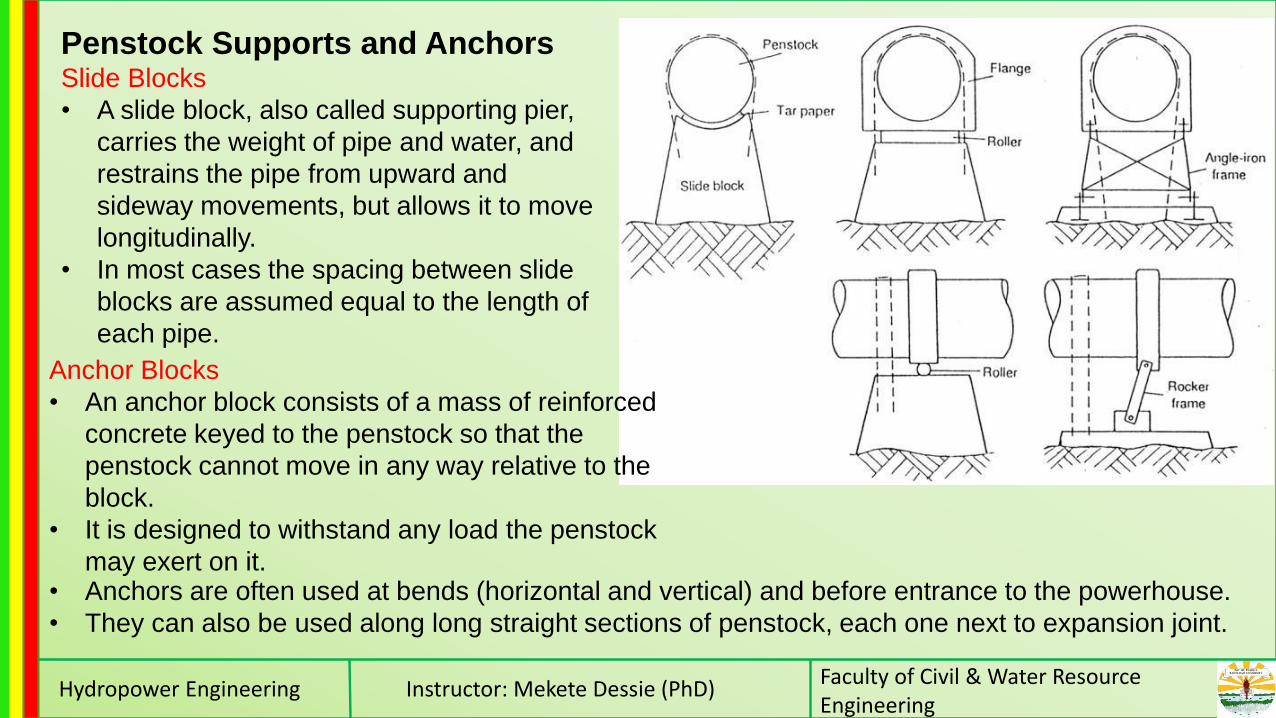
Penstock Supports and AnchorsSlide Blocks
• A slide block, also called supporting pier,
carries the weight of pipe and water, and
restrains the pipe from upward and
sideway movements, but allows it to move
longitudinally.
• In most cases the spacing between slide
blocks are assumed equal to the length of
each pipe.
Anchor Blocks
• An anchor block consists of a mass of reinforced
concrete keyed to the penstock so that the
penstock cannot move in any way relative to the
block.
• It is designed to withstand any load the penstock
may exert on it.• Anchors are often used at bends (horizontal and vertical) and before entrance to the powerhouse.
• They can also be used along long straight sections of penstock, each one next to expansion joint.

Hydropower Engineering Instructor: Mekete Dessie (PhD)Faculty of Civil & Water Resource Engineering

Hydropower Engineering Instructor: Mekete Dessie (PhD)Faculty of Civil & Water Resource Engineering
The major forces which act on anchor blocks are the
following
• Weight of the pipe and enclosed water
• Hydrostatic force on a bend
• Friction forces on slide blocks located between
the anchor and expansion joint
• Thermally induced stresses, when expansion
joints are not incorporated
• The weight of the anchor block itself
Conditions of Stability for Supports and Anchors
The structure should be safe against sliding. For sliding
not to occur:

Hydropower Engineering Instructor: Mekete Dessie (PhD)Faculty of Civil & Water Resource Engineering

Hydropower Engineering Instructor: Mekete Dessie (PhD)Faculty of Civil & Water Resource Engineering

Hydropower Engineering Instructor: Mekete Dessie (PhD)Faculty of Civil & Water Resource Engineering