Arch Book Solution Ch3 Sep
32
Chapter 3 Combinational Circuits 1
description
All achitechture
Transcript of Arch Book Solution Ch3 Sep

Chapter 3
Combinational Circuits
1

2 Chapter 3
3–1 Yes, it matters. The least significant input (input C in our example) must be connected to S 0, thenext input (input B) to S1, and so on.

Chapter 3 3
3–2 The AND implementation is shown below:
I 1
I 0
I 2
S0S1
I 3
MUX
F
BA
0
1
O0
0
FA B
0
0 1
1 0 0
1 1 1
0 0
0
AND truth table
The NOT implementation is shown below:
I 1
I 0
I 2
S0S1
I 3
MUX
F
A
O0
1FA
0
1
1
0
NOT truth table

4 Chapter 3
3–3 The AND implementation is shown below:
FA B
0
0 1
1 0 0
1 1 1
0 0
0
AND truth table
F
I 1
I 0
S0
F0
B
A
OUM
X
A
0
1
0
B
New truth table
The NOT implementation is shown below:
F
I 1
I 0
S0
F
A
0
1
1
0
NOT truth table
1
0
A
OUM
X

Chapter 3 5
3–4 The implementation is shown below:
I 0
I 1
I 2
I 3
S1
MUX
0
0
1
0
1
1
0
1
A B C
O
S0S2
I 4
I 5
I 6
I 7
F

6 Chapter 3
3–5 The implementation is shown below:
F FA B C A B
0 0
0 0 1
0 1 0 0
0 1 1 1
1 0 0 0
1 0 1 1
1 1 0 1
0 1
0
1 1 1 0
0 0 C
0 1 C
1 0 C
1 1 C
Original truth table New truth table
I 1
I 0
I 2
S0S1
I 3
MUX
BA
O F
C

Chapter 3 7
3–6 The implementation is shown below:
F1 F1
I 1
I 0
I 2
S0S1
I 3
MUX
A B C A B
0 0
0 0 1
0 1 0 0
0 1 1 1
1 0 0 1
1 0 1 1
1 1 0 1
0 0
0
1 1 1 1
0 0 0
0 1 C
1 0 1
1 1 1
Original truth table New truth table
BA
1
CO F1
1
0

8 Chapter 3
3–7 The implementation is shown below:
F1 F1
I 1
I 0
I 2
S0S1
I 3
MUX
A B C A B
0 0
0 0 1
0 1 0 0
0 1 1 0
1 0 0 0
1 0 1 1
1 1 0 1
0 0
0
1 1 1 1
0 0 0
0 1 0
1 0 C
1 1 1
Original truth table New truth table
BA
C
0O F1
1
0

Chapter 3 9
3–8 We use one 74151 with four inputs: two inputs are given through the XOR gate. The inputs of thisMUX are obtained from the following truth table:
A3 A2 A1
LA0 O1
0 0 0 0
0 0 1 1
0 1 0 1
0 1 1 0
1 0 0 1
1 0 1 0
1 1 0 0
1 1 1 1
For the second MUX, the output from the first MUX is given as one input. We use the reductiontechnique to connect the remaining three inputs (see the truth tables below):

10 Chapter 3
Original truth table
O1 A4 A5 A6 O2
0 0 0 0 0
0 0 0 1 1
0 0 1 0 1
0 0 1 1 0
0 1 0 0 1
0 1 0 1 0
0 1 1 0 0
0 1 1 1 1
1 0 0 0 1
1 0 0 1 0
1 0 1 0 0
1 0 1 1 1
1 1 0 0 0
1 1 0 1 1
1 1 1 0 1
1 1 1 1 0
Reduced truth table
O0 A4 A5 O2
0 0 0 A6
0 0 1 A6
0 1 0 A6
0 1 1 A6
1 0 0 A6
1 0 1 A6
1 1 0 A6
1 1 1 A6
The implementation is shown below:

Chapter 3 11
I0I1I2I3I4I5I6I7
0 I0I1I2I3I4I5I6I7
A6
P
S0S1S2
MUX
O
A2
10
0
1
A3
1
01
S0S1S2
MUX
O
A0A1
A5 A4
A6
A6
A6
A6
A6
A6
A6
Note that we need an inverter to generate A6.

12 Chapter 3
3–9 In ripple-carry adders, delay in the generation of result is proportional to the number of bits becauseof the carry propagation. We use them in practice because they are simple to implement.

Chapter 3 13
3–10 Carry lookahead adders produce the result in a constant time, independent of the number of bits.In ripple-carry adders, output delay is proportional to the number of bits due to carry propagation.However, carry lookahead adders are complex to implement compared to ripple-carry adders.
14 Chapter 3
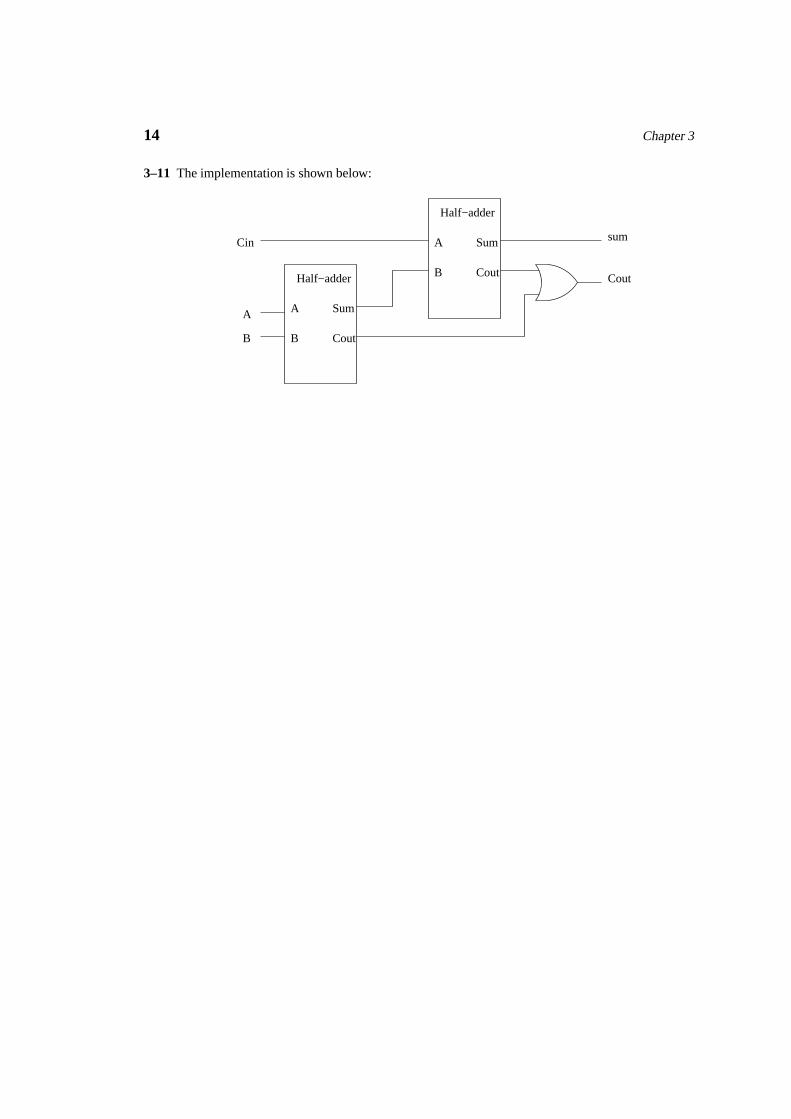
3–11 The implementation is shown below:
A
B
Sum
Cout
Half−adder
A
B
Sum
Cout
Half−adder
A
B
Cin sum
Cout

Chapter 3 15
3–12 The implementation is shown below:
Sum Cout
C outC inA B Sum
0 0 0 0 0
0 0 1 1 0
0 1 0 1 0
0 1 1 0 1
1 0 0 1 0
1 0 1 0 1
1 1 0 0 1
1 1 1 1 1
A B
0 0 Cin 0
0 1 Cin Cin
1 0 Cin Cin
1 1 Cin 1
Reduced truth table
Sum Cout
I 1a
I 0a
I 2a
S0S1
I 3a
MUX
I 1b
I 0b
I 2b
S0S1
I 3b
MUX
O bO a
E a E b
Full adder truth table
BA
Cin
Cin
Cin
Cin
BA
0
1
Cin
Cin
Strictly speaking, we need an inverter to complement Cin (i.e., to get Cin).

16 Chapter 3
3–13 The implementation is shown below:
Enableinput
O1 O0I 1a
I 0a
I 2a
S0S1
I 3a
MUX
I 1b
I 0b
I 2b
S0S1
I 3b
MUX
O bO a
E b
1
1
1
0
E a
I2I3 I2I3
1
0
I1
1
Strictly speaking, we need an inverter to complement Cin (i.e., to get Cin).

Chapter 3 17
3–14 The implementation of (A � B � Bin) is shown below:
Diff BoutI 1a
I 0a
I 2a
S0S1
I 3a
MUX
I 1b
I 0b
I 2b
S0S1
I 3b
MUX
O bO a
E a E b
BA
Bin
Bin
Bin
Bin
BA
A B Diff
0 0 0 0 0
0 0 1 1 1
0 1 0 1 1
0 1 1 0 1
1 0 0 1 0
1 0 1 0 0
1 1 0 0 0
1 1 1 1 1
Bin Bout A B
0 0
0 1 Bin 1
1 0 Bin 0
1 1 Bin Bin
Diff Bout
Full subtractor truth table Reduced truth table
Bin Bin
Bin
0
1
Bin
Strictly speaking, we need an inverter to complement Bin (i.e., to get Bin).

18 Chapter 3
3–15 The truth table is given below. If we eliminate variable D, we need an inverter. Eliminating inputA gives the answer we are looking for. The implementation is shown below:

Chapter 3 19
Number
0
1
2
3
4
5
6
7
Segment d
I0I1I2I3I4I5I6I7
1
1
1
1/0
1/0
1/0
1/0
1/0
1/0
8
9
10
11
12
13
14
15
0 0 0
0 0 1
0 1 0
0 1 1
1 0 0
1 0 1
1 1 0
1 1 1
1
0
1
1
0
1
1
0
Segment d truth table
A B C D segment d
0
0
0
0
0
0
0
0
0 0 0
0 0 1
0 1 0
0 1 1
1 0 0
1 0 1
1 1 0
1 1 1
1
A
1
1
0
1
1
0
B C D segment d
0 0 0
0 0 1
0 1 0
0 1 1
1 0 0
1 0 1
1 1 0
1 1 1
Reduced truth table
S0S1S2
MUX
O
C DB
1
0
01
11
A
1
1
1
1
1
1
1
1

20 Chapter 3
3–16 The implementation is shown below:
1
1
0
0
1
1
1
0
I0I1I2I3I4I5I6I7
0
A > B
0 0 0
0 0 1
0 1 0
0 1 1
1 0 0
1 0 1
1 1 0
1 1 1
0
0
0
0
1
0
0
0
1
1
1
1
1
1
1
1
0
0
0
0
0
0
0
0
0 0 0
0 0 1
0 1 0
0 1 1
1 0 0
1 0 1
1 1 0
1 1 1
A > BA1 A0 B1 B0
S0S1S2
MUX
O
A0
10
01
0B0
B0
B1A1
0
0
B0
0
1
0
1
B0
A1 A0 B1
0 0 0
0 0 1
0 1 0
0 1 1
1 0 0
1 0 1
1 1 0
1 1 1
Reduced truth table
A > B
Original truth table

Chapter 3 21
3–17 The implementation is shown below:
0
0
0
1
0
0
0
0
I0I1I2I3I4I5I6I7
B0
A < B
0 0 0
0 0 1
0 1 0
0 1 1
1 0 0
1 0 1
1 1 0
1 1 1
S0S1S2
MUX
O
B0
1
0
1
0
B0
0
0
A1 A0 B1
0 0 0
0 0 1
0 1 0
0 1 1
1 0 0
1 0 1
1 1 0
1 1 1
Reduced truth table
A < B
Original truth table
1
1
1
1
1
1
1
1
0
0
0
0
0
0
0
0
0 0 0
0 0 1
0 1 0
0 1 1
1 0 0
1 0 1
1 1 0
1 1 1
A < BA1 A0 B1 B0
0
1
1
1
0
0
1
1
A0
01
0
1
B1A1
B0
0
0

22 Chapter 3
3–18 The implementation is shown below:
0
0
0
0
0
0
1
0
I0I1I2I3I4I5I6I7
A > B
0
0 0 0
0 0 1
0 1 0
0 1 1
1 0 0
1 0 1
1 1 0
1 1 1
S0S1S2
MUX
O
0
1
B0
1
0
0
0
B0
A1 A0 B1
0 0 0
0 0 1
0 1 0
0 1 1
1 0 0
1 0 1
1 1 0
1 1 1
Reduced truth table
A > B
Original truth table
1
1
1
1
1
1
1
1
0
0
0
0
0
0
0
0
0 0 0
0 0 1
0 1 0
0 1 1
1 0 0
1 0 1
1 1 0
1 1 1
A > BA1 A0 B1 B0
0
0
1
1
1
0
1
1
A0
01
0
1
B1A1
B0
0
B0

Chapter 3 23
3–19 The implementation is shown below:
I0I1I2I3I4I5I6I7
C3
0
I0I1I2I3I4I5I6I7
C1
0 I0I1I2I3I4I5I6I7
C0
0I0I1I2I3I4I5I6I7
C2
0
0 0 0
0 0 1
0 1 0
0 1 1
1 0 0
1 0 1
1 1 0
1 1 1
0
0
0
1
B0
B0
B0
B0
S0S1S2
MUX
O
A0
00
0
0
B1A1
0
B0
0
S0S1S2
MUX
O
A0
1
0
B1A1
B0
0
B0B0B0
S0S1S2
MUX
O
A0
0
0
B1A1
B0
0
B0
B0
B0
S0S1S2
MUX
O
A0
00
0
0
B1A1
B0
1
0
A1 A0 B1
0 0 0
0 0 1
0 1 0
0 1 1
1 0 0
1 0 1
1 1 0
1 1 1
Reduced truth tableOriginal truth table
1
1
1
1
1
1
1
1
0
0
0
0
0
0
0
0
0 0 0
0 0 1
0 1 0
0 1 1
1 0 0
1 0 1
1 1 0
1 1 1
A1 A0 B0
0 0 0 0
0 0 0 0
0 0 0 0
0 0 0 0
0 0 0 0
0 0 0 0
0 0 0 0
0 0 1 1
0 1 1 0
1 0 0 1
0 1 1 0
0 0 1 0
0 1 0 0
0 0 1 1
0 0 1 0
0 0 0 1
C3 C2 C1 C0B1 C3 C2 C1 C0
0
0
0
0
0
1
0
B0
0
0
0
0
0
0
0
B0
0
0
B0
B0
0
0
B0
B0

24 Chapter 3
3–20 The implementation is shown below:
I0I1I2I3I4I5I6I7
Q0
0 I0I1I2I3I4I5I6I7
R1
0 I0I1I2I3I4I5I6I7
R0
0
I0I1I2I3I4I5I6I7
Q1
0
0 0 0
0 0 1
0 1 0
0 1 1
1 0 0
1 0 1
1 1 0
1 1 1
S0S1S2
MUX
O
A0
00
0
B1A1
B0B01
B0
S0S1S2
MUX
O
A0
0
0
B1A1
0
B00
00
S0S1S2
MUX
O
A0
0
0
B1A1
0
B00
10
S0S1S2
MUX
O
A1 A0 B1
0 0 0
0 0 1
0 1 0
0 1 1
1 0 0
1 0 1
1 1 0
1 1 1
Reduced truth tableOriginal truth table for A/B
1
1
1
1
1
1
1
1
0
0
0
0
0
0
0
0
0 0 0
0 0 1
0 1 0
0 1 1
1 0 0
1 0 1
1 1 0
1 1 1
A1 A0 B0
0 0 0 0
0 0 0 0
0 0 0 0
0 0 0 0
0 0 0 0
0 0 0 0
0 0 0 0
1 1 0 0
0 1 0 1
0 1 0 0
0 0 1 0
1 0 0 0
0 1 0 0
0 0 0 1
0 0 0 1
0 1 0 0
Q1 Q0 R1 R0B1 Q1 Q0 R1 R0
0
0
B0
0
0
B0
B0
1
0
0
0
0
B0
0
B0
0
0
0
0
1
0
0
0
B0
0
0
0
0
0
B0
0
0
A0
0
0
B1A1
0
0
B0
B00

Chapter 3 25
Note that we set quotient and remainder to zero when dividing by zero.

26 Chapter 3
3–21 PALs are very similar to PLAs except that there is no programmable OR array. Instead, ORconnections are fixed. As a result of this change to the OR array, there is a loss of flexibility thatsometimes may cause problems but in practice is not such a big problem. But the advantage ofPAL devices is that we can cut down all the OR array fuses that are present in a PLA.

Chapter 3 27
3–22 The full adder truth table is shown below:
C outC inA B Sum
0 0 0 0 0
0 0 1 1 0
0 1 0 1 0
0 1 1 0 1
1 0 0 1 0
1 0 1 0 1
1 1 0 0 1
1 1 1 1 1
Full adder truth table
The full adder implementation is shown below:
Sum
Cout
Cin
A
B
P P P P0 1 2 3 P P5 P6 P74
The full subtractor truth table is shown below:

28 Chapter 3
A B Diff
0 0 0 0 0
0 0 1 1 1
0 1 0 1 1
0 1 1 0 1
1 0 0 1 0
1 0 1 0 0
1 1 0 0 0
1 1 1 1 1
Bin Bout
Full subtractor truth table
The full subtractor implementation is shown below:
Diff
Bout
Bin
A
B
P P P P0 1 2 3 P P5 P6 P74

Chapter 3 29
3–23 The implementation is shown in the following figure:
I3
I1
I2
Enable
O1
O2
Note that we need just three gates from the AND array.

30 Chapter 3
3–24 The XOR gates acts as a programmable inverter. It complements theB input for (A�B) functionso that we can use the full adder for the subtract operation.

Chapter 3 31
3–25 This exercise is deleted. The XOR gate is deleted from the figure.

32 Chapter 3
3–26 See Exercise 3-12.