Arc Jet Testing of Thermal Protection Materials: 3 Case ... · Joe Conley, Chief, Thermal...
48
Sylvia Johnson, Chief Materials Technologist Joe Conley, Chief, Thermal Protection Materials Branch NASA Ames Research Center NSMMS 22 June 2015 Arc Jet Testing of Thermal Protection Materials: 3 Case Studies https://ntrs.nasa.gov/search.jsp?R=20160001278 2020-03-10T02:03:35+00:00Z
Transcript of Arc Jet Testing of Thermal Protection Materials: 3 Case ... · Joe Conley, Chief, Thermal...
Sylvia Johnson, Chief Materials Technologist Joe Conley, Chief, Thermal Protection Materials Branch NASA Ames Research Center
NSMMS 22 June 2015
Arc Jet Testing of
Thermal Protection Materials:
3 Case Studies
https://ntrs.nasa.gov/search.jsp?R=20160001278 2020-03-10T02:03:35+00:00Z

2
Entry Systems & Technology Division
Arc Jet Testing
Arc Jet Testing: TPS Case Studies !
Other than an actual flight test, arc jet facilities are the best available tool for testing materials and systems in high speed entry environments.
Arc jets provide a controlled test environment that approximates the heat fluxes, surface temperatures, enthalpies, pressures, flow, and shear experienced during high speed entries.
While arc jet facilities cannot duplicate all of the relevant parameters in any single test, a well designed test matrix in concert with material modeling and analysis can offer Mission teams confidence in validating the performance of their thermal protection materials and systems.
3
Entry Systems & Technology Division
Arc Jet Testing: TPS Case Studies !
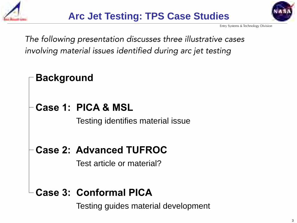
The following presentation discusses three illustrative cases involving material issues identified during arc jet testing
Background
Case 1: PICA & MSL Testing identifies material issue
Case 2: Advanced TUFROC Test article or material?
Case 3: Conformal PICA Testing guides material development
4
Entry Systems & Technology Division
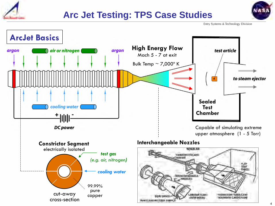
ArcJet Basics
Sealed Test
Chamber
cut-away cross-section
cooling water
test gas (e.g. air, nitrogen)
Constrictor Segment electrically isolated
99.99% pure
copper
High Energy Flow Mach 5 - 7 at exit
Capable of simulating extreme upper atmosphere (1 - 5 Torr)
Bulk Temp ~ 7,000º K
Interchangeable Nozzles
Arc Jet Testing: TPS Case Studies !
5
Entry Systems & Technology Division
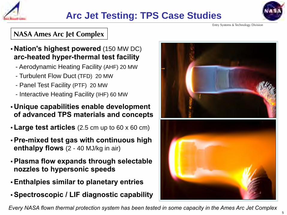
• Nation's highest powered (150 MW DC) arc-heated hyper-thermal test facility - Aerodynamic Heating Facility (AHF) 20 MW - Turbulent Flow Duct (TFD) 20 MW - Panel Test Facility (PTF) 20 MW - Interactive Heating Facility (IHF) 60 MW
• Unique capabilities enable development of advanced TPS materials and concepts
• Large test articles (2.5 cm up to 60 x 60 cm)
• Pre-mixed test gas with continuous high enthalpy flows (2 - 40 MJ/kg in air)
• Plasma flow expands through selectable nozzles to hypersonic speeds
• Enthalpies similar to planetary entries
• Spectroscopic / LIF diagnostic capability
Every NASA flown thermal protection system has been tested in some capacity in the Ames Arc Jet Complex
NASA Ames Arc Jet Complex
Arc Jet Testing: TPS Case Studies !
6
Entry Systems & Technology Division
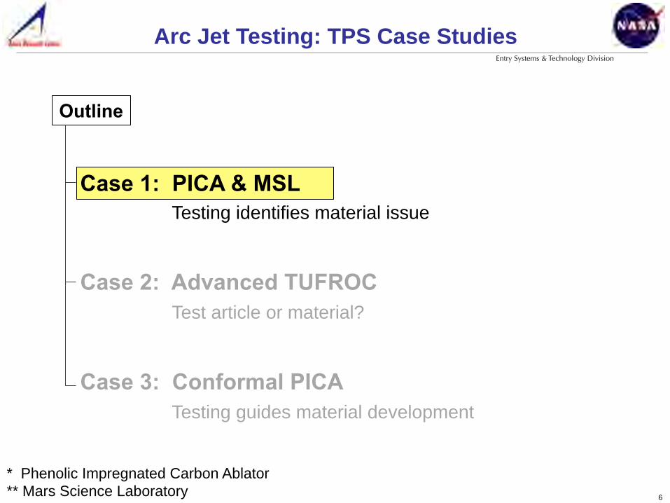
* Phenolic Impregnated Carbon Ablator ** Mars Science Laboratory
Arc Jet Testing: TPS Case Studies !
Case 1: PICA & MSL Testing identifies material issue
Case 2: Advanced TUFROC Test article or material?
Case 3: Conformal PICA Testing guides material development
Outline

7
Entry Systems & Technology Division
Objective of NASA's Mars Science Laboratory (MSL) program was to place an SUV size rover (Curiosity) safely on the surface of Mars
3 m (long) x 3 m (wide) x 2 m (tall) 900 kg, 6 wheels, 90 m/hr
Curiosity rover
Too heavy for airbags, MSL utilized a Sky Crane for a powered descent
Sky Crane with Rover
CASE 1: PICA & MSL!
8
Entry Systems & Technology Division
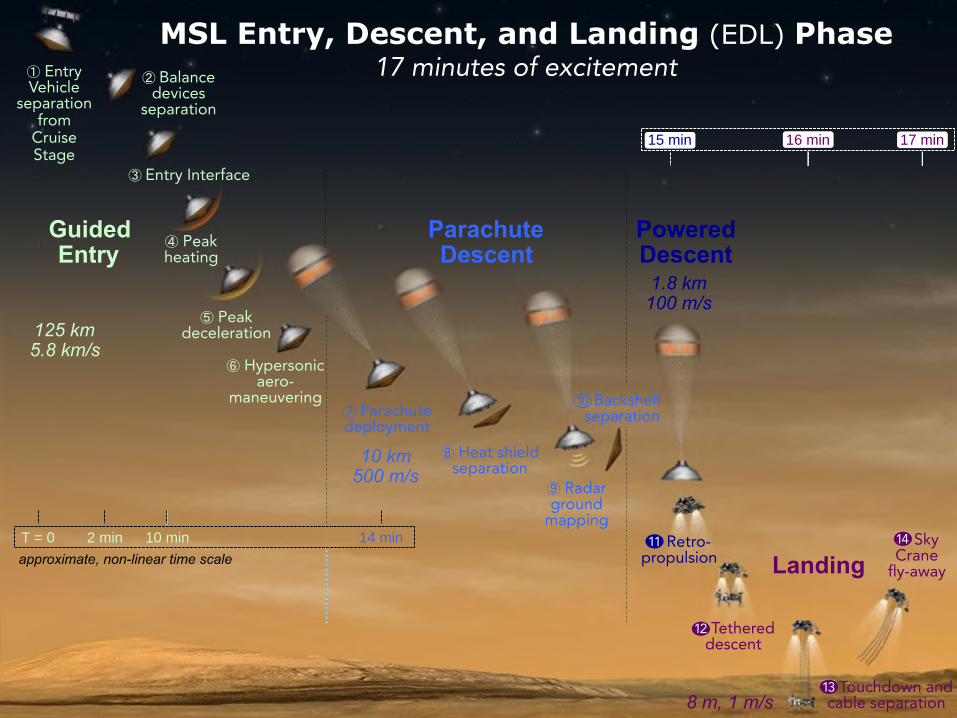
Powered Descent
1.8 km 100 m/s
Landing
8 m, 1 m/s
Parachute Descent
10 km 500 m/s
⑧ Heat shield separation
⑦ Parachute deployment
⑨ Radar ground
mapping 11 Retro-
propulsion
12 Tethered descent
14 Sky Crane
fly-away
1 4
Backshell separation
MSL Entry, Descent, and Landing (EDL) Phase 17 minutes of excitement
T = 0 2 min 10 min 14 min approximate, non-linear time scale
Guided Entry
125 km 5.8 km/s
① Entry Vehicle
separation from
Cruise Stage
② Balance devices
separation
④ Peak heating
③ Entry Interface
⑤ Peak deceleration
⑥ Hypersonic aero-
maneuvering
13 Touchdown and cable separation
1 3
1 2
1 1
1 0
15 min 17 min 16 min
9
Entry Systems & Technology Division
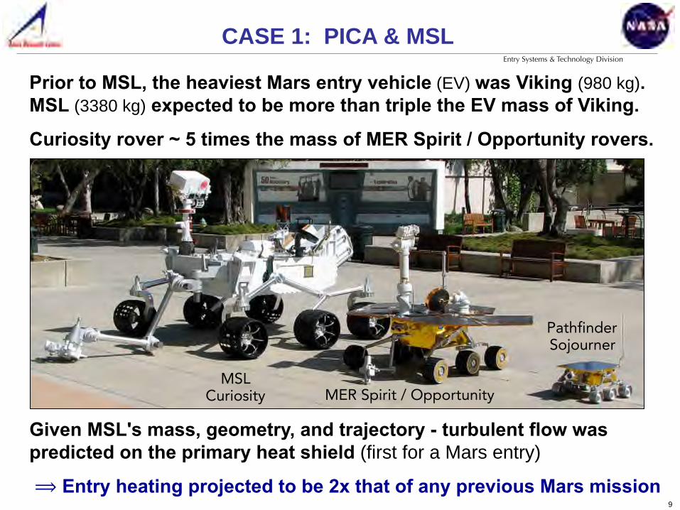
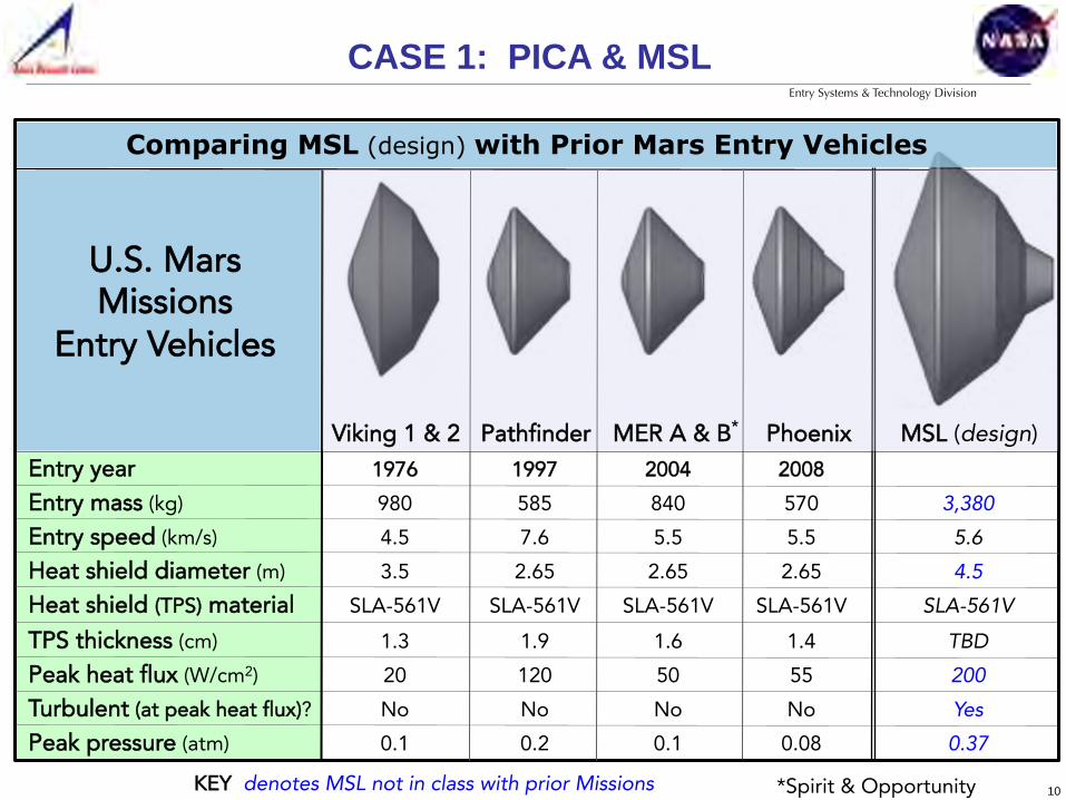
Prior to MSL, the heaviest Mars entry vehicle (EV) was Viking (980 kg). MSL (3380 kg) expected to be more than triple the EV mass of Viking.
Curiosity rover ~ 5 times the mass of MER Spirit / Opportunity rovers.
Given MSL's mass, geometry, and trajectory - turbulent flow was predicted on the primary heat shield (first for a Mars entry)
⟹ Entry heating projected to be 2x that of any previous Mars mission
MSL Curiosity MER Spirit / Opportunity
Pathfinder Sojourner
CASE 1: PICA & MSL!
10
Entry Systems & Technology Division
*Spirit & Opportunity
Entry year 1976 1997 2004 2008 Entry mass (kg) 980 585 840 570 3,380
Entry speed (km/s) 4.5 7.6 5.5 5.5 5.6
Heat shield diameter (m) 3.5 2.65 2.65 2.65 4.5 Heat shield (TPS) material SLA-561V SLA-561V SLA-561V SLA-561V SLA-561V TPS thickness (cm) 1.3 1.9 1.6 1.4 TBD Peak heat flux (W/cm2) 20 120 50 55 200
Turbulent (at peak heat flux)? No No No No Yes
Peak pressure (atm) 0.1 0.2 0.1 0.08 0.37
U.S. Mars Missions
Entry Vehicles
Viking 1 & 2 Pathfinder MER A & B* Phoenix MSL (design)
Comparing MSL (design) with Prior Mars Entry Vehicles
CASE 1: PICA & MSL!
KEY denotes MSL not in class with prior Missions

11
Entry Systems & Technology Division
• Glass vaporization allowed material to withstand heat fluxes > 300 W/cm2
• No failures observed
• High fidelity SLA-561V material model matched stagnation arc jet tests
SLA Stagnation Testing for MSL
• MSL baselined SLA-561V, which performed well in stagnation arc jet testing and was heatshield material for all previous Mars missions
CASE 1: PICA & MSL!
30 W/cm2
210 W/cm2
90 W/cm2
270 W/cm2
150 W/cm2
300 W/cm2
MSL Stagnation Test Articles (SLA-561V)

12
Entry Systems & Technology Division
• Arc jet testing in shear environments yielded catastrophic material failures - Recession rate was 20+ times predicted values - Filler material seemed to disintegrate and evacuate the cells - Not a melt-fail; not correlated to shear force
SLA Shear Testing for MSL
t = 14 sec t = 16 sec t = 18 sec
• Material failure reproducible at certain conditions
CASE 1: PICA & MSL!
13
Entry Systems & Technology Division
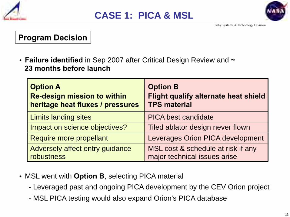
Program Decision
CASE 1: PICA & MSL!
Option B
PICA best candidate Tiled ablator design never flown Leverages Orion PICA development MSL cost & schedule at risk if any major technical issues arise
Flight qualify alternate heat shield TPS material
Re-design mission to within heritage heat fluxes / pressures Limits landing sites Impact on science objectives? Require more propellant Adversely affect entry guidance robustness
Option A
• Failure identified in Sep 2007 after Critical Design Review and ~ 23 months before launch
• MSL went with Option B, selecting PICA material - Leveraged past and ongoing PICA development by the CEV Orion project - MSL PICA testing would also expand Orion's PICA database

14
Entry Systems & Technology Division
High surface area resin morphology yields desirable thermal performance
PICA consists of carbon substrate* impregnated with phenolic resin
Phenolic Resin
impregnation
curing +
PICA
Carbon Fiber
Substrate
Carbon Fibers Pre-Impregnation low density, randomly arranged
*Fiberform™
Low phenolic loading matrix uniformly
distributed throughout the substrate material
CASE 1: PICA & MSL!
Carbon Fibers Post-Processing connected via 'fluffy' phenolic

15
Entry Systems & Technology Division
• Design, develop, test, build, and qualify a PICA heat shield for an April 2009 delivery ( < 18 months from start!)
• Fortunately, to date Orion had conducted 125 arc jet tests of PICA - Tested to more severe environments (heating, pressure, shear) - Various gap filler designs - Material characterization (material property tests) performed - High fidelity model developed for in-depth thermal and recession response
CASE 1: PICA & MSL!
Go-Forward Plan
• MSL could simplify design because the aeroshell structure was composite (vs metallic for Orion) - CTE agreement was better - Lower deflections in MSL enabled direct bonding
to structure and filled gaps

16
Entry Systems & Technology Division
• MSL PICA design worked in parallel with PICA manufacturing - Maximum allowable gap size originally based on Orion tests - Gap size then refined via thermal/structural analysis; verified through tests
• TPS sizing selected at 1.25" (3.175 cm) without detailed testing or analysis - Conservative over-design - 1.25" based on maximum mass allowed by spacecraft mass budget
Not much time!
• Symmetric heat shield selected to minimize aero-torques
• Tiled architecture driven by - PICA processing limitations - Aerothermal environments - Thermal-mechanical requirements
CASE 1: PICA & MSL!

17
Entry Systems & Technology Division
• Gap-filled specimens simulated cruise-to-entry effects - Low and high heat fluxes - With and without pre-cooling
• Tests using in-depth instrumentation verified PICA thermal response model
• Predicted recession rates within 20% of measured values from arc jet tests - MSL-relevant conditions - Predictions not as good at low heat rates - TITAN: 2D thermal response model
PICA Stagnation Testing
CASE 1: PICA & MSL!
18
Entry Systems & Technology Division
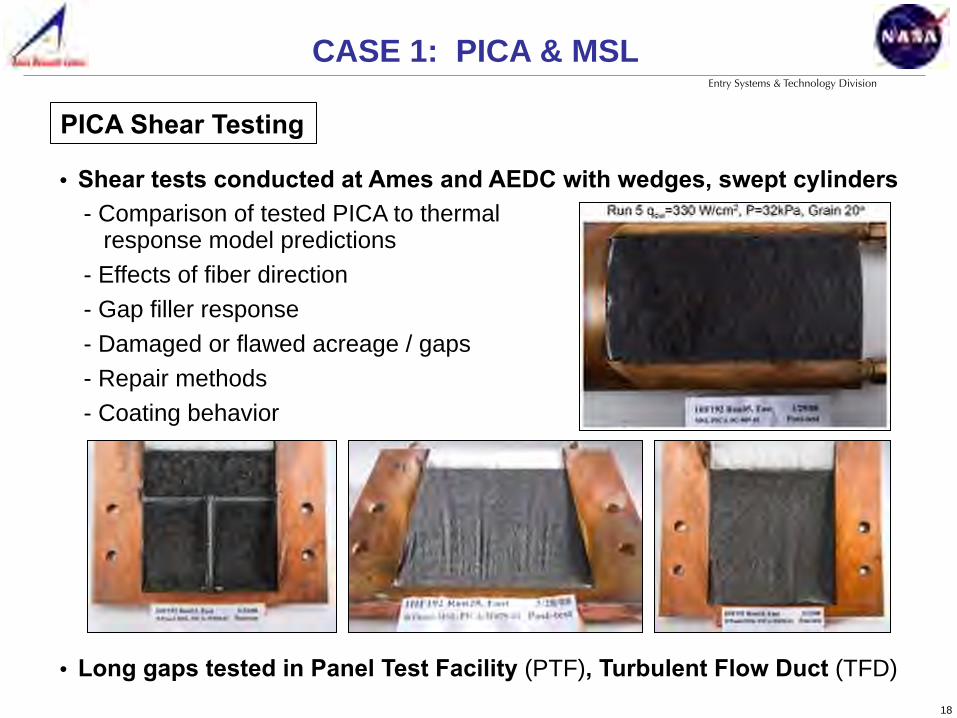
• Shear tests conducted at Ames and AEDC with wedges, swept cylinders - Comparison of tested PICA to thermal response model predictions - Effects of fiber direction - Gap filler response - Damaged or flawed acreage / gaps - Repair methods - Coating behavior
PICA Shear Testing
CASE 1: PICA & MSL!
• Long gaps tested in Panel Test Facility (PTF), Turbulent Flow Duct (TFD)

19
Entry Systems & Technology Division
• Extensive PICA arc jet test series utilized 100+ test articles
• PICA material robust at all tested conditions including those where SLA-561V experienced failures
• RTV-560 filled gaps performed well
• Recession rates varied from model predictions, but could be modeled and bounded conservatively
• Heat Shield thickness - Up front, program decision was to set it at 1.25” - Analysis and margining process yielded a thickness of 0.94" - So, as built vehicle had 0.31” extra thermal protection material / margin
PICA Test Results
CASE 1: PICA & MSL!
20
Entry Systems & Technology Division
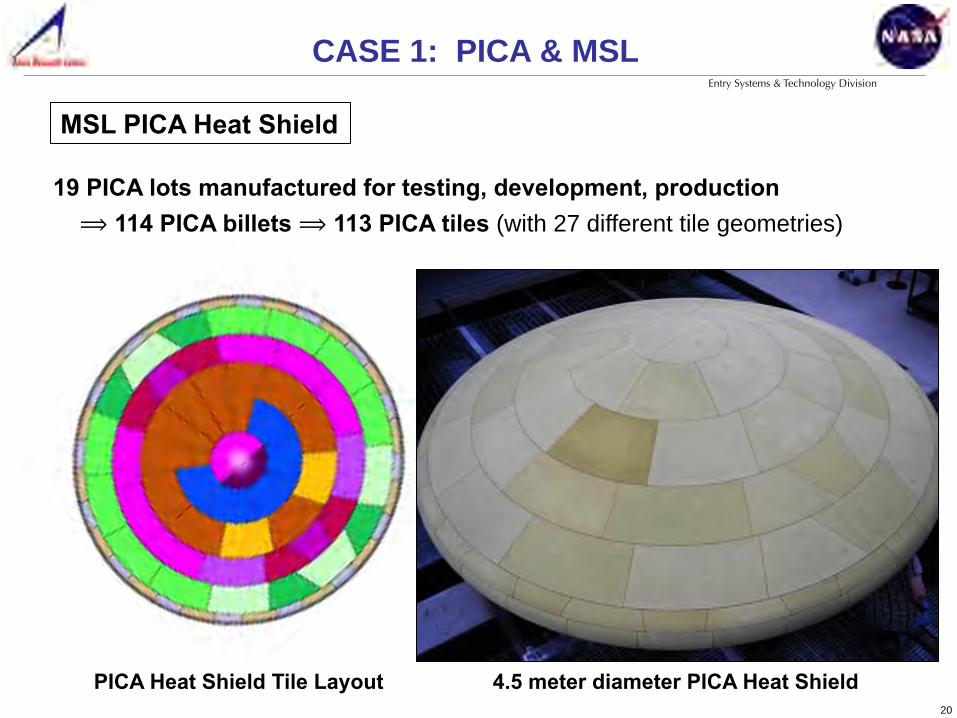
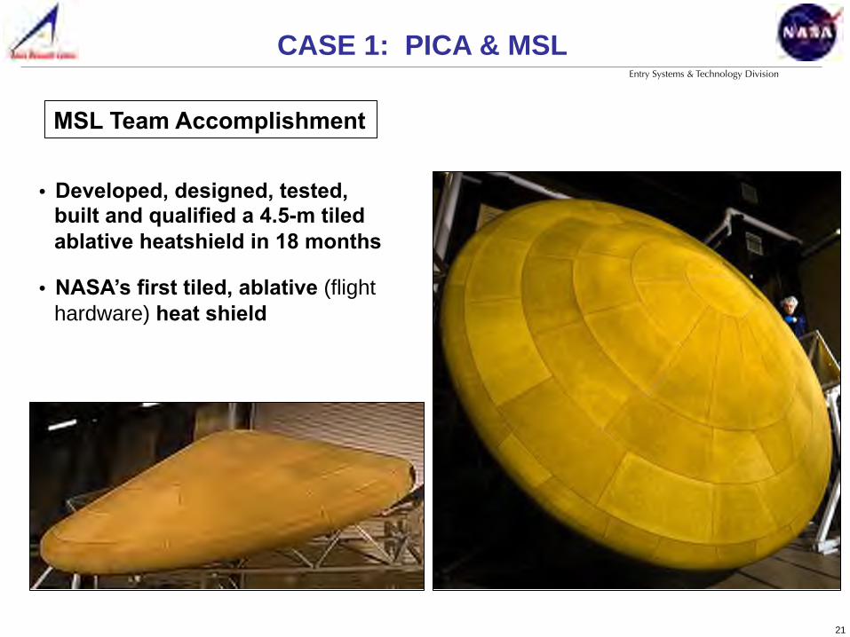
19 PICA lots manufactured for testing, development, production ⟹ 114 PICA billets ⟹ 113 PICA tiles (with 27 different tile geometries)
MSL PICA Heat Shield
4.5 meter diameter PICA Heat Shield PICA Heat Shield Tile Layout
CASE 1: PICA & MSL!
21
Entry Systems & Technology Division
• Developed, designed, tested, built and qualified a 4.5-m tiled ablative heatshield in 18 months
• NASA’s first tiled, ablative (flight hardware) heat shield
MSL Team Accomplishment
CASE 1: PICA & MSL!
22
Entry Systems & Technology Division
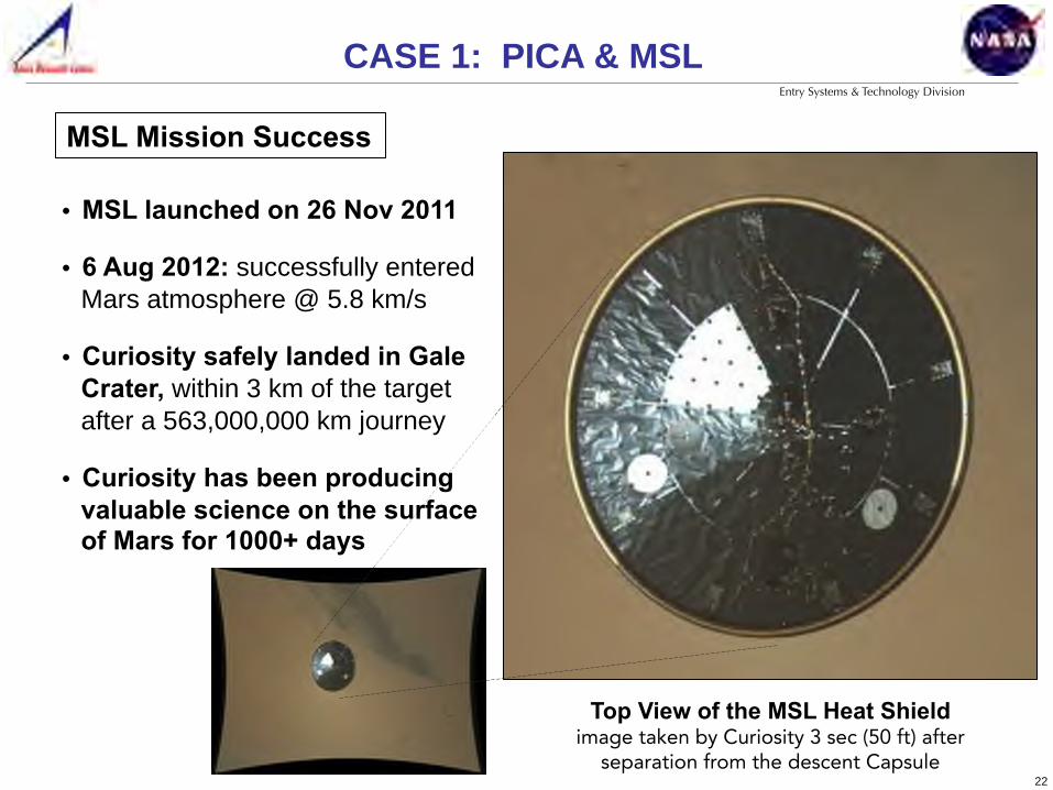
MSL Mission Success
Top View of the MSL Heat Shield image taken by Curiosity 3 sec (50 ft) after
separation from the descent Capsule
• MSL launched on 26 Nov 2011
• 6 Aug 2012: successfully entered Mars atmosphere @ 5.8 km/s
• Curiosity safely landed in Gale Crater, within 3 km of the target after a 563,000,000 km journey
• Curiosity has been producing valuable science on the surface of Mars for 1000+ days
CASE 1: PICA & MSL!
23
Entry Systems & Technology Division
* Toughened Uni-piece Fibrous Reinforced Oxidation Resistant Composite
Arc Jet Testing: TPS Case Studies !
Case 1: PICA & MSL Testing identifies material issue
Case 2: Advanced TUFROC* Test article or material?
Case 3: Conformal PICA Testing guides material development
Outline

24
Entry Systems & Technology Division
- DoD Missions - Space Station support - Commercial access (satellite servicing, tourism, manufacturing)
Major technical gap: low cost, reusable TPS for high temp surfaces
While the Space Shuttle was a technical marvel, there remains a national need for low cost, reliable access to and from Earth orbit
25
Entry Systems & Technology Division
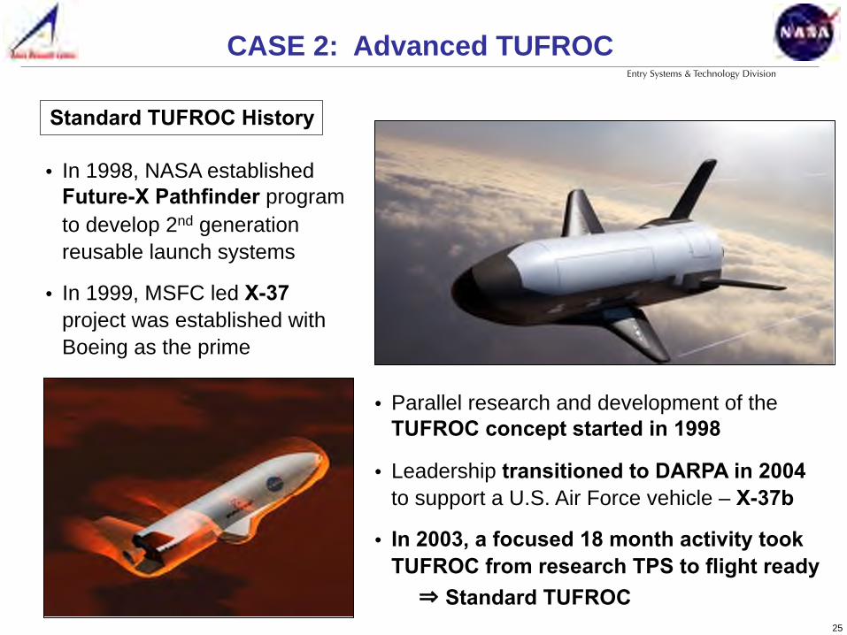
• In 1998, NASA established Future-X Pathfinder program to develop 2nd generation reusable launch systems
• In 1999, MSFC led X-37 project was established with Boeing as the prime
• Parallel research and development of the TUFROC concept started in 1998
• Leadership transitioned to DARPA in 2004 to support a U.S. Air Force vehicle – X-37b
• In 2003, a focused 18 month activity took TUFROC from research TPS to flight ready
Standard TUFROC History
CASE 2: Advanced TUFROC!
⇒ Standard TUFROC

26
Entry Systems & Technology Division
Flight Proven Standard TUFROC
TUFROC spans USAF X-37b wing leading edge - NASA developed Standard TUFROC and
transferred it to X-37b Prime - Boeing - Enabling technology for critical USAF Program - 3 successful missions, 4th mission in progress
Reusability of Standard TUFROC? ⇒ Advanced
X-37b Preparing for 1st launch, Apr 2010 12/8/2010
X-37b after 224 days (90 million miles) in orbit, Dec 2010
TUFROC TUFROC
CASE 2: Advanced TUFROC!
27
Entry Systems & Technology Division
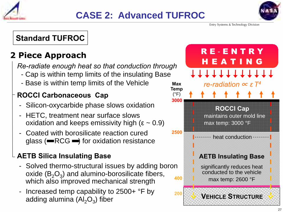
ROCCI Carbonaceous Cap - Silicon-oxycarbide phase slows oxidation - HETC, treatment near surface slows
oxidation and keeps emissivity high (ε ~ 0.9) - Coated with borosilicate reaction cured
glass ( RCG ) for oxidation resistance AETB Silica Insulating Base - Solved thermo-structural issues by adding boron
oxide (B2O3) and alumino-borosilicate fibers, which also improved mechanical strength
- Increased temp capability to 2500+ °F by adding alumina (Al2O3) fiber
Standard TUFROC
2 Piece Approach Re-radiate enough heat so that conduction through - Cap is within temp limits of the insulating Base - Base is within temp limits of the Vehicle
AETB Insulating Base
re-radiation ∝ ε T4
significantly reduces heat conducted to the vehicle
max temp: 2600 °F
3000
2500
400
200
R E - E N T R Y H E A T I N G
Max Temp (°F)
VEHICLE STRUCTURE
heat conduction
ROCCI Cap maintains outer mold line max temp: 3000 °F
CASE 2: Advanced TUFROC!

28
Entry Systems & Technology Division
ROCCI Carbonaceous Cap - Silicon-oxycarbide phase slows oxidation - High temp HETC surface treatments that
helps mitigate ROCCI – RCG CTE issues - Improved, higher viscosity RCG to handle
repeated cycles at higher temperatures AETB Silica Insulating Base - Solved thermo-structural issues by adding boron
oxide (B2O3) and alumino-borosilicate fibers, which also improved mechanical strength
- Increased temp capability to 2500+ °F by adding alumina (Al2O3) fiber
Advanced TUFROC
2 Piece Approach Re-radiate enough heat so that conduction through - Cap is within temp limits of the insulating Base - Base is within temp limits of the Vehicle
AETB Insulating Base
re-radiation ∝ ε T4
significantly reduces heat conducted to the vehicle
max temp: 2600 °F
3000
2500
400
200
R E - E N T R Y H E A T I N G
Max Temp (°F)
VEHICLE STRUCTURE
heat conduction
ROCCI Cap
CASE 2: Advanced TUFROC!
maintains outer mold line max temp: 3100 °F
29
Entry Systems & Technology Division
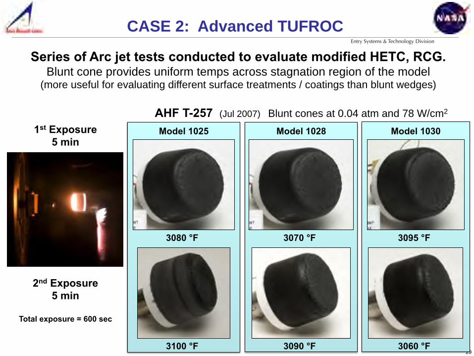
2nd Exposure 5 min
Total exposure = 600 sec
AHF T-257 (Jul 2007) Blunt cones at 0.04 atm and 78 W/cm2
Model 1025
3080 °F
3100 °F
1st Exposure 5 min
3070 °F
3090 °F
Model 1028
3095 °F
3060 °F
Model 1030
Series of Arc jet tests conducted to evaluate modified HETC, RCG. Blunt cone provides uniform temps across stagnation region of the model
(more useful for evaluating different surface treatments / coatings than blunt wedges)
CASE 2: Advanced TUFROC!
30
Entry Systems & Technology Division
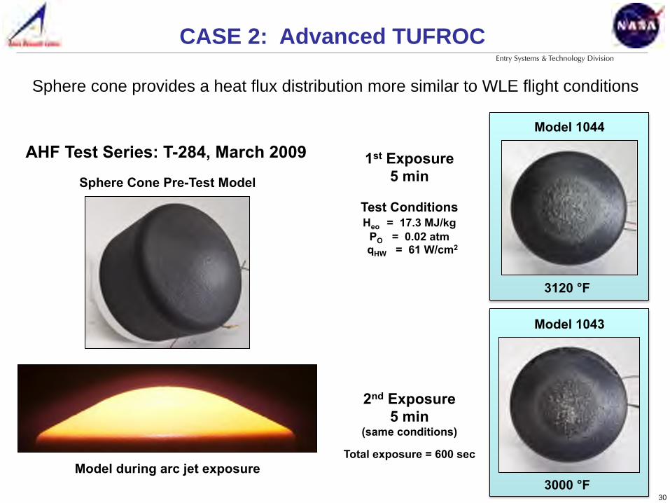
2nd Exposure 5 min
(same conditions)
Total exposure = 600 sec
1st Exposure 5 min
3120 °F
Model 1044
Model 1043
3000 °F
Test Conditions Heo = 17.3 MJ/kg
PO = 0.02 atm qHW = 61 W/cm2
Sphere Cone Pre-Test Model
Model during arc jet exposure
AHF Test Series: T-284, March 2009
CASE 2: Advanced TUFROC!
Sphere cone provides a heat flux distribution more similar to WLE flight conditions

31
Entry Systems & Technology Division
AHF Arc-Jet Exposure on Test Article 1043 (Mod IV)
Unfiltered Test Image Filtered Test Image Post Test Article
Arc jet test exposed corner issue with the sphere cone model
CASE 2: Advanced TUFROC!
Test article issue or a material issue relevant to flight hardware?
Tw = 3,000° F He0 = 17.5 MJ/kg P0 = 0.02 atm
Tw - wall temperature He0 - enthalpy at the boundary layer edge P0 - pressure at the stagnation point
32
Entry Systems & Technology Division
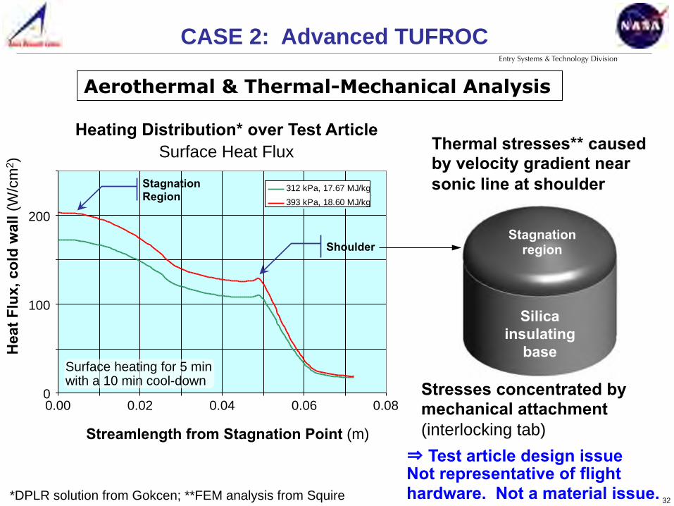
*DPLR solution from Gokcen; **FEM analysis from Squire
CASE 2: Advanced TUFROC!
Aerothermal & Thermal-Mechanical Analysis
Surface Heat Flux
0
50
100
150
200
250
0.000 0.010 0.020 0.030 0.040 0.050 0.060 0.070 0.080Streamlength from Stagnation Point (m)
Cold
Wal
l Hea
t Flu
x (W
/cm
2 )
312 kPa, 17.67 MJ/kg393 kPa, 18.60 MJ/kg
Shoulder
Stagnation Region
Streamlength from Stagnation Point (m)
0.02 0.04 0.06 0.08 0.00 0
100
200
Hea
t Flu
x, c
old
wal
l (W
/cm
2 )
Heating Distribution* over Test Article Surface Heat Flux
Surface heating for 5 min with a 10 min cool-down
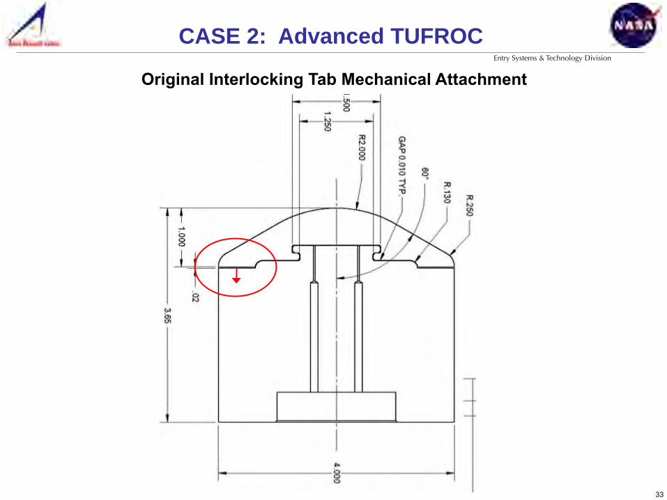
Thermal stresses** caused by velocity gradient near sonic line at shoulder
⇒ Test article design issue Not representative of flight hardware. Not a material issue.
Silica insulating
base
Stagnation region
Stresses concentrated by mechanical attachment (interlocking tab)
33
Entry Systems & Technology Division
Original Interlocking Tab Mechanical Attachment
CASE 2: Advanced TUFROC!

34
Entry Systems & Technology Division
CASE 2: Advanced TUFROC!
Re-designed Interlocking Tab Mechanical Attachment
35
Entry Systems & Technology Division
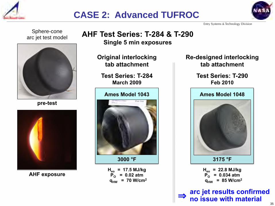
pre-test
AHF Test Series: T-284 & T-290 Single 5 min exposures
Original interlocking tab attachment
Re-designed interlocking tab attachment
Sphere-cone arc jet test model
AHF exposure
CASE 2: Advanced TUFROC!
Heo = 17.5 MJ/kg PO = 0.02 atm
qHW = 70 W/cm2
Ames Model 1043
3000 °F
Test Series: T-284 March 2009
Heo = 22.8 MJ/kg PO = 0.034 atm
qHW = 85 W/cm2
3175 °F
Ames Model 1048
Test Series: T-290 Feb 2010
arc jet results confirmed no issue with material ⇒
36
Entry Systems & Technology Division
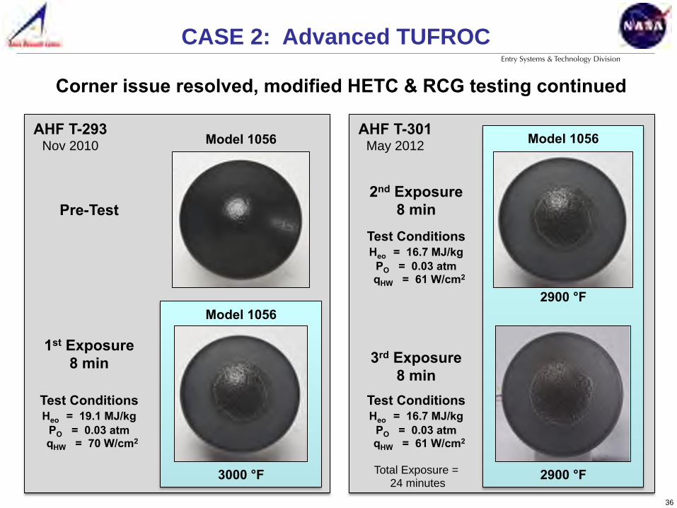
1st Exposure 8 min
Pre-Test
Test Conditions Heo = 19.1 MJ/kg
PO = 0.03 atm qHW = 70 W/cm2
Model 1056
3000 °F
Model 1056
AHF T-293 Nov 2010 Model 1056
2900 °F
2900 °F
3rd Exposure 8 min
2nd Exposure 8 min
Test Conditions Heo = 16.7 MJ/kg
PO = 0.03 atm qHW = 61 W/cm2
Test Conditions Heo = 16.7 MJ/kg
PO = 0.03 atm qHW = 61 W/cm2
AHF T-301 May 2012
Total Exposure = 24 minutes
CASE 2: Advanced TUFROC!
Corner issue resolved, modified HETC & RCG testing continued

37
Entry Systems & Technology Division
Model H-1087
1000
2000
3000 Te
mpe
ratu
re (°
F)
0 200 400 600 800 Time (sec)
8 minutes Heo = 19 MJ/kg PO = 0.02 atm
qHW = 62 W/cm2
1st 8 min Exposure 2900 °F
Tem
pera
ture
(°F)
1000
2000
3000
0 200 400 600 800 Time (sec)
2nd 8 min Exposure 3000 °F
Heo = 20 MJ/kg PO = 0.025 atm
qHW = 70 W/cm2
Time (sec)
Tem
pera
ture
(°F)
Surface
Interface
IML 1000
2000
3000
0 200 400 600 800
3rd 8 min Exposure 3000 °F
Heo = 20 MJ/kg PO = 0.025 atm
qHW = 70 W/cm2
AHF Test Series: T-301 May 2012 (24 minutes, total exposure time)
CASE 2: Advanced TUFROC!

38
Entry Systems & Technology Division
CASE 2: Advanced TUFROC!
• Repeatable arc jet testing of the modified TUFROC demonstrated a multiple use capability
• Modified TUFROC material and processing specification frozen and branded as Advanced TUFROC
• Technology transfer of Advanced TUFROC has started with Boeing and Sierra Nevada Corporation
TUFROC R&D Success!
X-37b, April 2015 credit USAF
Standard TUFROC performed better than expected as demonstrated by a successful re-flight of X-37b wing leading edge tiles
39
Entry Systems & Technology Division
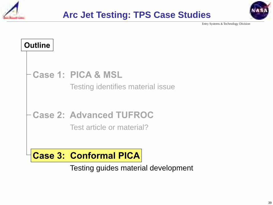
Arc Jet Testing: TPS Case Studies !
Case 1: PICA & MSL Testing identifies material issue
Case 2: Advanced TUFROC Test article or material?
Case 3: Conformal PICA Testing guides material development
Outline

40
Entry Systems & Technology Division
Motivation
• TPS integration is hard and expensive
• Current heat shield types all have issues / limitations - Monolithic: limited by size (< 1 m diameter) - Tile: complex with gap and seam issues - Honeycomb: complex with gore and curing issues - Compatibility with sub-structure (strain, CTE, etc.)
CASE 3: Conformal PICA!
Monolithic Stardust Capsule 0.8 m diameter PICA Heat Shield
Tiled SpaceX Dragon & Heat Shield (PICA-X) 5 m diameter. 4 successful 8 km/s Earth re-entries 2010-13.
Honeycomb Orion Heat Shield (Avcoat) 5 m diameter. Successful Flight Test (EFT-1) Dec 2014

41
Entry Systems & Technology Division
• Compliant (high strain to failure) nature simplifies TPS integration on a wide range of aeroshell structures
• Also enables configuration of over large areas, thus reducing
- part count - number of seams - installation complexity ⇒ time and cost
Conformal TPS
CASE 3: Conformal PICA!
• Offers a promising solution to a number of challenges faced by traditional rigid (low strain-to-failure) TPS materials

42
Entry Systems & Technology Division
• Developed using commercially available low density rayon-based carbon felt from Morgan
• Demonstrated uniform fabrication of a sample 12-inch square and demonstrated conformability of the system over 3-inch radius
Initial Development
CASE 3: Conformal PICA!

43
Entry Systems & Technology Division
0.0#
0.1#
0.2#
0.3#
0.4#
0.5#
0.6#
0.7#
0.8#
0.9#
1.0#
PICA# Conformal#1# PICA# CPICA# PICA#Normalized
+Recession
++0.0#
0.1#
0.2#
0.3#
0.4#
0.5#
0.6#
0.7#
0.8#
0.9#
1.0#
PICA# Conformal#1# PICA# CPICA# PICA#
Normalized
+Recession
++
• Initial formulation of Conformal TPS tested at: Heat Flux: 1000 W/cm2
Pressure: 0.85 atm
• Conformal 1 appeared to recede 2x faster than PICA
• Testing identified erosive failure of material
• Work begun to reduce the recession difference between PICA and Conformal TPS
Initial Testing
CASE 3: Conformal PICA!
PICA
Conformal 1

44
Entry Systems & Technology Division
• Work on Conformal 1 culminated in the development of Conformal PICA (CPICA) - Increased phenolic content and incorporated
additives to increase char strength
- CPICA recession still > PICA, but not 2x
- Too much resin content causes delamination due to shrinkage stresses from resin cure
- Higher density felt resolves this issue
CASE 3: Conformal PICA!
Redevelopment - Conformal PICA
0.0#
0.1#
0.2#
0.3#
0.4#
0.5#
0.6#
0.7#
0.8#
0.9#
1.0#
PICA# CPICA# PICA# CPICA# Advanced#CPICA#Normalized
+Recession
++0.0#
0.1#
0.2#
0.3#
0.4#
0.5#
0.6#
0.7#
0.8#
0.9#
1.0#
PICA# CPICA# PICA# CPICA# Advanced#CPICA#
Normalized
+Recession
++

45
Entry Systems & Technology Division
• Investigated felt substrate density vs. effect on TPS ablation performance
• Used commercial needling to increase felt density and increase substrate toughness
• Areas of exploration - Required strength in the felt
substrate? - Possible thickness? - Desired thickness? - Resin impregnation in denser
felts? - Felt densification vs structural
integrity?
Approach – Advanced Conformal TPS
CASE 3: Conformal PICA!

46
Entry Systems & Technology Division
Advanced CPICA
CASE 3: Conformal PICA!
Advanced Conformal TPS – Accomplishment
0.0#
0.1#
0.2#
0.3#
0.4#
0.5#
0.6#
0.7#
0.8#
0.9#
1.0#
PICA# CPICA# Advanced#CPICA# CPICA# PICA#
Normalized
+Recession
++
0.0#
0.1#
0.2#
0.3#
0.4#
0.5#
0.6#
0.7#
0.8#
0.9#
1.0#
PICA# CPICA# Advanced#CPICA# CPICA# PICA#
Normalized
+Recession
++
0.0#
0.1#
0.2#
0.3#
0.4#
0.5#
0.6#
0.7#
0.8#
0.9#
1.0#
PICA# CPICA# Advanced#CPICA# CPICA# PICA#
Normalized
+Recession
++
Advanced CPICA
• Advanced CPICA substrate density increased substantially from previous generation of felt
• Arcjet tested 0.14 g/cm3 felt infused with phenolic at 1850 W/cm2 heat flux, 1.4 atm
• Recession of Advanced CPICA now less than both PICA and previous CPICA

47
Entry Systems & Technology Division
MSL Program & Helen Hwang*, Robin Beck*
STMD Conformal Flexible Ablators Project & Matt Gasch*
Tom Squire*, Mike Wright*, Tahir Gocken*
Acknowledgements
Arc Jet Testing: TPS Case Studies !
* NASA Ames Research Center

48
Entry Systems & Technology Division
Arc Jet Testing: TPS Case Studies !
Acronyms not identified in the charts RCG Reaction Cured Glass AETB Alumina Enhanced Thermal Barrier HETC High Efficiency Tantalum-based Composite ROCCI Refractory Oxidation-resistant Ceramic Carbon Insulation