Aquifer Underground Pumped Hydroelectric Energy Storage€¦ · Aquifer Underground Pumped...
5
Aquifer Underground Pumped Hydroelectric Energy Storage Gregory D. Martin (University of Colorado - Boulder; Boulder, Colorado; [email protected]) Frank S. Barnes (University of Colorado - Boulder) I. Introduction Pumped hydroelectric energy storage (PHES) is the dominant technology currently deployed for storing large amounts of energy for the generation of electricity. Unfortunately, the feasibility of these systems is heavily dependent on geography, geology, local regulations and water usage policy. To address some of these concerns, underground pumped hydroelectric energy storage (UPHS) has been proposed. UPHS systems need only one surface reservoir (the forebay), with a subterranean reservoir (the afterbay) and power plant. A conceptual diagram of a generic UPHS system is shown in Figure 1. The underground reservoir can be any structure that has the capability to store water without compromising water quality or structural integrity. The authors could find no evidence of an installed, working UPHS system anywhere. The reason for this is likely the cost of building an afterbay deep underground, sealing it, and maintaining structural stability. Evidenced by the literature, a surge in interest in UPHS occurred in the late 1970s and early 1980s, but apparent interest has fallen off since then. While it has been claimed that the economic capacity of a UPHS plant would be in the range of 1000 to 3000 MW [1], there is no evidence of studies of smaller systems in the literature. With the advent of modern renewable energy sources, advanced excavating techniques, and considerable computer modeling capability, it is time to revisit this promising energy storage technology. Figure 1: Conceptual Diagram of UPHS System. This paper outlines an underground pumped hydroelectric energy storage (UPHS) concept for small to medium sized systems (less than 1 MW). This new concept proposes adapting UPHS to use a surface reservoir as the forebay and an underground aquifer, cavern, or mine as the afterbay. When used to support agricultural operations, it is expected that this concept is more cost effective than comparable energy storage solutions, is adaptable to more sites than traditional PHES, and has lower environmental and aesthetic impact. The target applications include agricultural operations, residential systems, distributed energy storage installations, and on- or off-grid small community scale energy storage. II. System Description Aquifer UPHS utilizes an integrated pump-turbine unit located below the surface of the aquifer water level that either pumps water to the surface or generates electricity from water released from the surface reservoir. Generally, the concept is envisioned to be coupled with a renewable generation source such as a wind turbine or photovoltaic solar source. At times of high output from the source, water is pumped to the surface reservoir. When power is demanded by the application, this surface water is released down through the turbine to generate electricity. In an agricultural setting, the same water may be simultaneously pumped to crops for irrigation, using power generated from the turbine. Figure 2 provides an illustration of the envisioned system.
Transcript of Aquifer Underground Pumped Hydroelectric Energy Storage€¦ · Aquifer Underground Pumped...

Aquifer Underground Pumped Hydroelectric Energy Storage Gregory D. Martin (University of Colorado - Boulder; Boulder, Colorado; [email protected]) Frank S. Barnes (University of Colorado - Boulder) I. Introduction Pumped hydroelectric energy storage (PHES) is the dominant technology currently deployed for storing large amounts of energy for the generation of electricity. Unfortunately, the feasibility of these systems is heavily dependent on geography, geology, local regulations and water usage policy. To address some of these concerns, underground pumped hydroelectric energy storage (UPHS) has been proposed. UPHS systems need only one surface reservoir (the forebay), with a subterranean reservoir (the afterbay) and power plant. A conceptual diagram of a generic UPHS system is shown in Figure 1. The underground reservoir can be any structure that has the capability to store water without compromising water quality or structural integrity. The authors could find no evidence of an installed, working UPHS system anywhere. The reason for this is likely the cost of building an afterbay deep underground, sealing it, and maintaining structural stability. Evidenced by the literature, a surge in interest in UPHS occurred in the late 1970s and early 1980s, but apparent interest has fallen off since then. While it has been claimed that the economic capacity of a UPHS plant would be in the range of 1000 to 3000 MW [1], there is no evidence of studies of smaller systems in the literature. With the advent of modern renewable energy sources, advanced excavating techniques, and considerable computer modeling capability, it is time to revisit this promising energy storage technology.
Figure 1: Conceptual Diagram of UPHS System.
This paper outlines an underground pumped hydroelectric energy storage (UPHS) concept for small to medium sized systems (less than 1 MW). This new concept proposes adapting UPHS to use a surface reservoir as the forebay and an underground aquifer, cavern, or mine as the afterbay. When used to support agricultural operations, it is expected that this concept is more cost effective than comparable energy storage solutions, is adaptable to more sites than traditional PHES, and has lower environmental and aesthetic impact. The target applications include agricultural operations, residential systems, distributed energy storage installations, and on- or off-grid small community scale energy storage. II. System Description Aquifer UPHS utilizes an integrated pump-turbine unit located below the surface of the aquifer water level that either pumps water to the surface or generates electricity from water released from the surface reservoir. Generally, the concept is envisioned to be coupled with a renewable generation source such as a wind turbine or photovoltaic solar source. At times of high output from the source, water is pumped to the surface reservoir. When power is demanded by the application, this surface water is released down through the turbine to generate electricity. In an agricultural setting, the same water may be simultaneously pumped to crops for irrigation, using power generated from the turbine. Figure 2 provides an illustration of the envisioned system.

Figure 2: Aquifer UPHS System Concept Illustration.
Energy is stored in the form of gravitation potential energy of the weight of the water in the surface reservoir with respect to the subterranean water table. Simply put, after water has been pumped out of the well to the surface, the water can then be released from the surface back to the aquifer, reversing the operation of the motor pump to generate electricity (as a turbine generator). To determine the amount of power that can be produced by releasing water back down to the aquifer, the following equation applies (neglecting dynamic head effects):
P = generated output power in Watts [W] Q = fluid flow in cubic meters per second [m3/s] ρ = fluid density in kilograms per cubic meter [kg/m3] = 1000 [kg/m3] for water H = hydraulic head height in meters [m] g = acceleration due to gravity [m/s2] = 9.81 [m/s2] on earth η = efficiency To implement this system, a pump-turbine coupled with an electrical motor-generator is installed as a single unit submerged in the water table. In large UPHS installations, the powerhouse (pump - turbine) is located below the lower reservoir to avoid water hammering issues. In the proposed system, the weight of water is not believed to be large enough to produce water hammering issues that cannot be alleviated using motor control and generator control methods. Since turbine efficiency decreases as head height decreases, the system needs to have a reasonable height between the bottom of surface reservoir and the top of the water table. It is recommended to have at least 150 feet of head, and ideal installations will have 200-800 feet of head. See Figure 3 for the relationship between power, head, and flow of such a system assuming a generating efficiency of 70%. From agricultural operations analysis, the desired range of output power for an irrigation system is about 40 kW to 150 kW, depending on site specifics. This range is shown as a shaded region on the y-axis of Figure 3. From previous well characteristics analysis, a maximum flow of 2000 gpm can reasonably be expected. The minimum flow for a feasible system is assumed here to be 500 gpm. The range of flow rates is shown as a shaded region on the x-axis of Figure 3. Also from well characteristics analysis, 800 feet is chosen as an upper bound for hydraulic head. The family of lines on Figure 3 represent power curves at different hydraulic heads, as labeled. Finally, the intersection of these three regions is outlined with a bold triangle. This triangle gives the range of hydraulic heads and flow rates needed to give the desired power output range.
An electric control and conversion center interfaces the energy source, the hydro motor-generator, and the user connection to the system. This controller can optimize the system performance by matching the pump load to the energy source to extract maximum power from the sun or wind [2]. The controller would also decide when to supply user demand directly from the energy source or from stored energy, as well as when to pump water using excess generated energy from the wind or solar source.
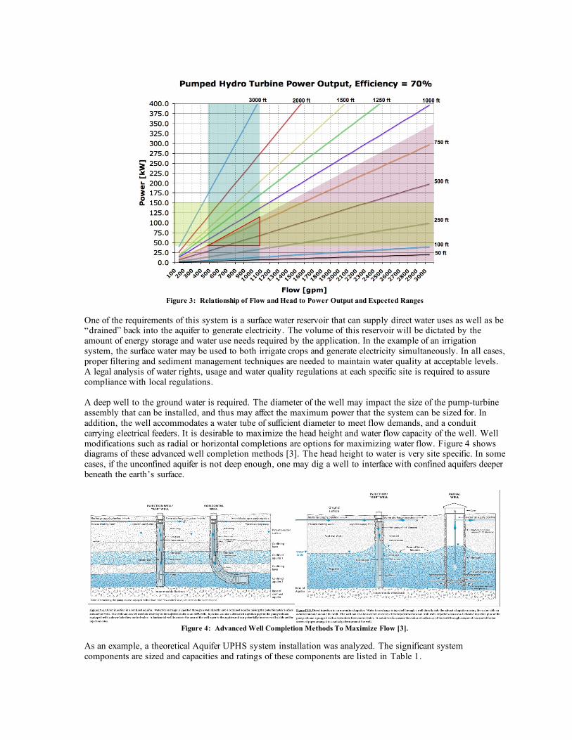
Figure 3: Relationship of Flow and Head to Power Output and Expected Ranges
One of the requirements of this system is a surface water reservoir that can supply direct water uses as well as be “drained” back into the aquifer to generate electricity. The volume of this reservoir will be dictated by the amount of energy storage and water use needs required by the application. In the example of an irrigation system, the surface water may be used to both irrigate crops and generate electricity simultaneously. In all cases, proper filtering and sediment management techniques are needed to maintain water quality at acceptable levels. A legal analysis of water rights, usage and water quality regulations at each specific site is required to assure compliance with local regulations. A deep well to the ground water is required. The diameter of the well may impact the size of the pump-turbine assembly that can be installed, and thus may affect the maximum power that the system can be sized for. In addition, the well accommodates a water tube of sufficient diameter to meet flow demands, and a conduit carrying electrical feeders. It is desirable to maximize the head height and water flow capacity of the well. Well modifications such as radial or horizontal completions are options for maximizing water flow. Figure 4 shows diagrams of these advanced well completion methods [3]. The head height to water is very site specific. In some cases, if the unconfined aquifer is not deep enough, one may dig a well to interface with confined aquifers deeper beneath the earth’s surface.
Figure 4: Advanced Well Completion Methods To Maximize Flow [3].
As an example, a theoretical Aquifer UPHS system installation was analyzed. The significant system components are sized and capacities and ratings of these components are listed in Table 1.
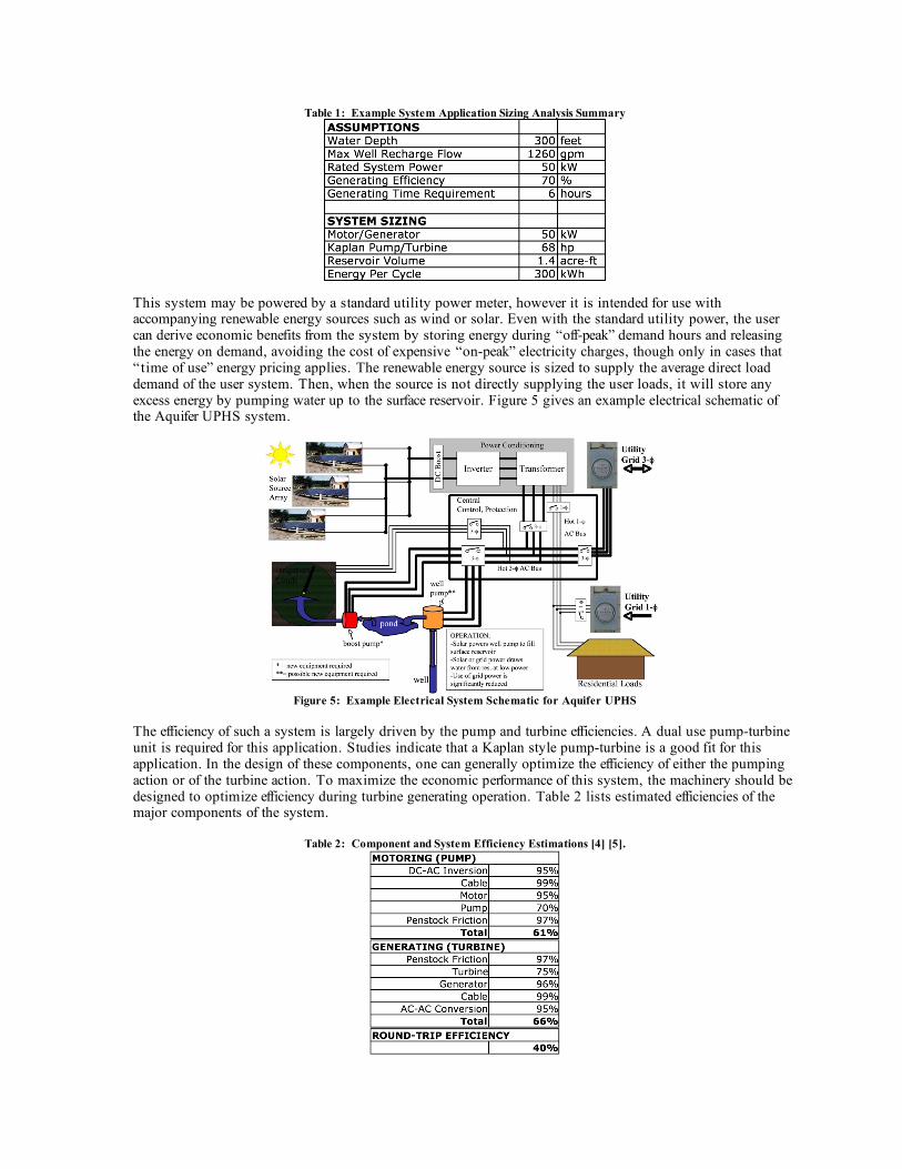
Table 1: Example System Application Sizing Analysis Summary
This system may be powered by a standard utility power meter, however it is intended for use with accompanying renewable energy sources such as wind or solar. Even with the standard utility power, the user can derive economic benefits from the system by storing energy during “off-peak” demand hours and releasing the energy on demand, avoiding the cost of expensive “on-peak” electricity charges, though only in cases that “time of use” energy pricing applies. The renewable energy source is sized to supply the average direct load demand of the user system. Then, when the source is not directly supplying the user loads, it will store any excess energy by pumping water up to the surface reservoir. Figure 5 gives an example electrical schematic of the Aquifer UPHS system.
Figure 5: Example Electrical System Schematic for Aquifer UPHS
The efficiency of such a system is largely driven by the pump and turbine efficiencies. A dual use pump-turbine unit is required for this application. Studies indicate that a Kaplan style pump-turbine is a good fit for this application. In the design of these components, one can generally optimize the efficiency of either the pumping action or of the turbine action. To maximize the economic performance of this system, the machinery should be designed to optimize efficiency during turbine generating operation. Table 2 lists estimated efficiencies of the major components of the system.
Table 2: Component and System Efficiency Estimations [4] [5].

The economics of such a system depend heavily on the presence of a useable surface reservoir, suitable well, and existing irrigation water pumps. In some cases, the irrigation well may have to be re-completed to increase the flow capability of the well (Figure 4). If a surface reservoir or pond is not available, one would need to be installed, incurring a significant portion of the total system cost. In addition, filtering or water treatment provisions may need to be added to accommodate water quality regulations for water being returned to the aquifer. Table 3 provides cost estimations for the example installation included above. The system is rated for 50 kW of power generation for 6 hours. In general, the cost of Aquifer UPHS is a less than the cost to install renewable generating sources. For PV solar installations, this storage method costs approximately 40% of the cost of the solar source. For wind turbine installations, this system would be nearer 70% of the wind turbine installation costs.
Table 3: Aquifer UPHS System Cost Estimation
III. Conclusions In this paper, a new concept for the underground pumped hydroelectric storage of energy is presented. Studies indicate that this system is a promising candidate for use in small renewable energy plants, especially agricultural energy systems. Estimations of efficiency and cost are provided for an example application sizing. Future work will refine the technical analysis of the hydro and electric systems involved in the concept, economic analysis, and siting considerations. IV. References [1] Allen, R. D.; Doherty, T. J.; Kannberg, L. D., “Underground pumped hydroelectric storage”, Pacific
Northwest Lab., Richland, WA., July 1984. [2] Mohammad A. S. Masoum, Hooman Dehbonei, Ewald F. Fuchs, “Theoretical and Experimental Analyses
of Photovoltaic Systems With Voltage- and Current-Based Maximum Power-Point Tracking”, IEEE Transactions on Energy Conversion, Vol. 17, No. 4, December 2002.
[3] Ralf Topper, Peter E. Barkmann, David A. Bird, and Matthew A. Sares, “Artifical Recharge of
Groundwater in Colorado – A Statewide Assessment”, Colorado Geological Survey, Environmental Geology 13, Department of Natural Resources, Denver, Colorado, 2004.
[4] Pump efficiency <http://www.mcnallyinstitute.com/07-html/7-2.html>
<http://www.mcnallyinstitute.com/06-html/6-01.html> [5] Turbine efficiency <http://www.canyonhydro.com/Resources/Guide/HydroGuide12.htm>