AquaForce Booster System Sizing Brochure
16
Goulds Pumps AquaForce™ Pressure Boosting Sizing Guide Building and Municipal Applications BRAQFOR ITT Engineered for life ANSI/ NSF 61 certified for public drinking water.
-
Upload
nitin-p-kumare -
Category
Documents
-
view
55 -
download
1
description
press bnoosting sys
Transcript of AquaForce Booster System Sizing Brochure

Goulds PumpsAquaForce™ Pressure Boosting Sizing GuideBuilding and Municipal Applications
BRAQFOR
ITT
Engineered for life
ANSI/ NSF 61 certified for public drinking water.

2
Goulds PumpsAquaForce™ Pressure Boosting Sizing Guide
1 Pump with 4 Gate valves 8 Pressure gauges AQUAVAR controller 5 Check valves 9 Level switches2 Diaphragm tank 6 Foot valves 10 Supply tank3 Distribution panel 7 Incoming pressure switch 11 Pressure Transmitter
Indirect connectionvia tank
Suction out of a well Direct connection
9
9
10
6
3
2
47
8
51
11
4
8
47
51
11
4
47
51
11
4
AquaForce GENERAL INFORMATIONAquaForce GENERAL INFORMATIONAquaForce GENERAL INFORMATIONThe AquaForce pump station is provided as a pre-engineered answer for installations requir-ing consistent water pressure with variable flow rates. The AquaForce can be selected and installed for many applications including: hotels, commercial buildings, public buildings, schools, hospitals, domestic water, irrigation, general industrial process, municipal water supply, rural water supply, RO water, wash systems and general water boosting. Each of these applications typically sees varying de-mand during the day, but the users demand a consistent water pressure even in periods of peak use.Goulds Pumps has developed the AquaForce pump station to meet this need. The Aqua-Force consists of either two (duplex) or three (triplex) pumps mounted to a common steel base. These pumps may be either horizontal end suction or vertical multistage design based on the required pressure. Pump liquid end components and the common suction and dis-charge manifolds are all provided in stainless steel. Each station also includes all required
gate valves, check valves, pressure transducers and gages.Each pump is equipped with its own Aquavar variable speed pump controller, which is de-scribed in more detail in the following section. A central fuse panel with individual pump dis-connects is provided to assist with shut down for maintenance. The entire AquaForce station carries the UL and CUL certification for control panels and complete pumping systems.The AquaForce can be connected to either sur-face or underground supply tanks or directly to municipal water supply. The following diagram shows the various piping layouts available for both duplex and triplex pump stations. Both suction and discharge manifolds are supplied with flanges at each end for either left hand or right hand installation.NOTE: Each pump in the AquaForce station is sized with the same maximum flow rate. For duplex stations, each pump can produce 50% of total flow. Same sized pumps are used for duplex or triplex.

3
COMMON APPLICATIONSCOMMON APPLICATIONSCOMMON APPLICATIONS
Municipal Water System
TyPICAL G&L PuMPS PROduCT TyPICAL G&L PuMPS PROduCT Applications AquaForce AquaBoost Aquavar Turbine SSV SSH SMVT MPVN 1 Raw Water Pumping X X X
2 Industrial Source Water X X X X X X X
3 Municipal Booster Station X X X X X X X
4 Residential Booster X
5 Hotel Water Boost X X X X X X
6 Hospital Water Boost X X X X
7 Industrial Water Boost X X X X X X X
8 Schools Water Boost X X X X
9 Office Buildings X X X X X X X
10 Shopping Centers X X X X X
4
Goulds PumpsAquaForce™ Pressure Boosting Sizing Guide
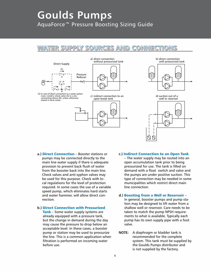
WATER SuPPLy SOuRCES ANd CONNECTIONSWATER SuPPLy SOuRCES ANd CONNECTIONSWATER SuPPLy SOuRCES ANd CONNECTIONS
a.) direct Connection – Booster stations or pumps may be connected directly to the main line water supply if there is adequate provision to prevent back flush of water from the booster back into the main line. Check valves and anti-syphon valves may be used for this purpose. Check with lo-cal regulations for the level of protection required. In some cases the use of a variable speed pump, which eliminates hard starts and water hammer, will allow direct con-nection.
b.) direct Connection with Pressurized Tank – Some water supply systems are already equipped with a pressure tank, but the change in demand during the day may cause the pressure to drop below an acceptable level. In these cases, a booster pump or station may be used to pressurize the line. This is a common application when filtration is performed on incoming water before use.
c.) Indirect Connection to an Open Tank – The water supply may be routed into an open accumulation tank prior to being pressurized for use. The tank is filled on demand with a float switch and valve and the pumps are under positive suction. This type of connection may be needed in some municipalities which restrict direct main line connection.
d.) Boosting from a Well or Reservoir – In general, booster pumps and pump sta-tion may be designed to lift water from a shallow well or reservoir. Care needs to be taken to match the pump NPSH require-ments to what is available. Typically each pump has its own supply pipe with a foot valve.
NOTE: A diaphragm or bladder tank is recommended for the complete system. This tank must be supplied by the Goulds Pumps distributor and is not supplied by the factory.
(2)
A
B
a) direct connectionwithout pressurized tank
c) indirect connection to anopen break tank
b) direct connectionwith pressurized tank
d) suction out of awell or reservoir
Direct Supply
PressureReducer
(2) In case of direct connection to a water systemmain, install a check valve (A) or a dis-connecting device (B), unless otherwisestated in local codes.

5
COMMON dESIGNS FOR BuILdING BOOSTER SySTEMSCOMMON dESIGNS FOR BuILdING BOOSTER SySTEMSCOMMON dESIGNS FOR BuILdING BOOSTER SySTEMSWater supply boosting for multi-story build-ings can take many different configurations depending on the availability of main line pres-sure, the height of the building and the size of the booster unit.In general, water pressure in a residential or commercial building should not fall below 20 psi at the point of use. When pressures drop below this point, common appliances
and plumbing fixtures will no longer function properly.At the most favorable point of use, the pres-sure should not exceed 70 psi. Pressures beyond this may lead to failure of piping joints, fixtures and appliances.The following diagrams show six common con-figurations of main line and booster pressure use to meet these requirements.
BOOSTERUNIT
SUPPLY
≥ 20 psi
≤ 70 psi
BOOSTERUNIT
SUPPLY
≥ 20 psi
≤ 70 psi
A) The unit serves the entire building. B) The unit serves the entire building, but the lower floors are connected through a pressure reducer since the pressure to the nearest utiliza-tion point is too high.
C) The unit serves the upper floors, whereas the lower floors are supplied by the water pipe under pressure.
D) This case resembles the previous one except that pressure reducers need to be installed on some of the lower floors.
BOOSTERUNIT
SUPPLY
≥ 20 psi
≤ 70 psi
WATER PIPEUNDER PRESSURE
SUPPLY
≥ 20 psi
≤ 70 psi
WATER PIPEUNDER PRESSURE
BOOSTERUNIT
≤ 70 psi

6
Goulds PumpsAquaForce™ Pressure Boosting Sizing Guide
COMMON dESIGNS FOR BuILdING BOOSTER SySTEMSCOMMON dESIGNS FOR BuILdING BOOSTER SySTEMSCOMMON dESIGNS FOR BuILdING BOOSTER SySTEMS
E) The height of the building requires two booster units to be used.
F) This case resembles the previous one, except that the lower floors are fed by the water pipe under pressure (Ex. water system).
SUPPLY
≥ 20 psi
BOOSTERUNIT No. 2
≤ 70 psi
BOOSTERUNIT No. 1 SUPPLY
≥ 20 psi
BOOSTERUNIT No. 2
≤ 70 psi
BOOSTERUNIT No. 1
WATER PIPEUNDER PRESSURE
Hc
He
H TOTAL
Hr
HsTANK
BOOSTER UNIT
Calculating Total dynamic Head
The Total Dynamic Head (TDH) for your booster application is calculated as follows:
TDH = He + Hr + Hc – Hs
Where:
– He is the vertical height difference between the booster discharge and the highest point of use.
– Hr is the friction losses of all of the piping, valves, elbows, etc. of the system.
– Hc is the desired discharge pressure at the top of the system.
– Hs is any suction pressure coming into the booster from the water supply line.
For details on calculating friction losses, see the tables in the technical data section of your G&L Pumps catalog or friction loss tables for piping.
Example:
The highest tap in a building is 70 feet above the pump. Friction losses from piping add up to 30 feet, the user wants 50 psi (116 feet) available and there is 25 psi (58 feet) of suction pressure at the pump.
TDH = (He) + (Hr) + (Hc) – (Hs)TDH = 70 + 30 + 116 – 58TDH = 158 feet

7
CALCuLATING MAXIMuM FLOW RATESCALCuLATING MAXIMuM FLOW RATESCALCuLATING MAXIMuM FLOW RATESIn addition to determining the Total Dynamic Head required by your installation, you will also need to estimate the maximum flow rate required before you can select the correct pump station.
Two methods of estimating the maximum flow rate for different types of buildings are shown on this page. You can use the graph method if you know the number of apartments in an apartment house, the number of employees in offices or stores, or the number of beds in hospitals and hotels.
A somewhat more accurate method is to use the total number of plumbing fixtures in the building. If you can get a fairly accurate count of the total fixtures, you can use the chart on the bottom of the page to determine how much flow to allow for each fixture in the vari-ous types of buildings.
For example, in a hospital with 250 fixtures, the demand per fixture would be .50 gal-lons per minute or a total of 125 GPM for the hospital’s booster system at peak demand.
APARTMENT HOUSES
NU
MB
ER O
F A
PAR
TMEN
TS
0
20
40
60
80100
120
140
160
180
200
0 4 9 13 17 22 27 31 35 40 44 48 53 57 61 66 70GPM
NU
MB
ER O
F EM
PLO
YEES
0
200400
600
8001000
1200
1400
1600
1800
2000
0 44 88 132 176 220 264
OFFICE BLO
CKS
SHOPPING CENTER
GPM
NU
MB
ER O
F B
EDS
0
200
400
600
800
1000
1200
0 44 88 132 176 220 264
HOSPITALS
HOTELS
308 352 396GPM
PUMP CAPACITY REQUIRED IN U.S. GALLONS PER MINUTE PER FIXTURE FOR PUBLIC BUILDINGS
Type of Total Number of Fixtures Building 25 26 51 101 201 401 Over or Less -50 -100 -200 -400 -600 600
Hospitals 1.00 1.00 .80 .60 .50 .45 .40
Mercantile Buildings 1.30 1.00 .80 .71 .60 .54 .48
Office Buildings 1.20 .90 .72 .65 .50 .40 .35
Schools 1.20 .85 .65 .60 .55 .45
Hotels, Motels .80 .60 .55 .45 .40 .35 .33
Apartment Buildings .60 .50 .37 .30 .28 .25 .24
1. For less than 25 fixtures, pump capacity should not be less than 75% of capacity required for 25 fixtures.
2. Where additional water is required for some special process, this should be added to pump capacity.
3. Where laundries or swimming pools are to be supplied, add approxi-mately 10% to pump capacity for either.

8
Goulds PumpsAquaForce™ Pressure Boosting Sizing Guide
1000800
600500400
80
60
40
20
10 30CAPACITY (GPM)
TOTA
L D
YNA
MIC
HEA
D (T
DH)
FEET
300
200
150
100
50
30
1020 40 50 60 70 200 300 400 500 600 800 1000 120080 90 100 700 900 1100 1500
22SH30 HP (3)6SH
20 HP (3)
6SH15 HP (3)
22SH30 HP (2)
6SH20 HP (2)
6SH15 HP (2)
8SH20 HP (3)
5SH15 HP (3)
6SVB 5 Stg (3)6SVB4 Stg (3)
5SH71/2 HP (3)
5SVB8 Stg (3)
8SH20 HP (2)
5SH15 HP (2)
5SVB5 Stg (3)
5SH71/2 HP (2)
4SH5 HP(2)
4SH10 HP(2)
7SH15 HP (2)
5SVB5 Stg (2)
5SVB8 Stg (2)4SVB
8 Stg (2)11SH
20 HP (2)11SH
15 HP (2)
10SH10 HP (2)
4SVB10 Stg (2)
2ST5 HP (3)
2ST3 HP(3)
2ST3 HP(2)
2ST5 HP (2)
3SVB13 Stg (3)
3SVB11 Stg (3)
3SVB9 Stg(3)
3SVB6 Stg(3)
3SVB4 Stg(3)
3SVB9 Stg(2)
3SVB6 Stg(2)
3SVB4 Stg(2)
3SVB 13 Stg (2)3SVB 11 Stg (2)
2SVB 15 Stg (3)2SVB 13 Stg (3)2SVB11 Stg (3)2SVB8 Stg (3)
2SVB6 Stg (3)
2SVB 15 Stg (2)2SVB 13 Stg (2)2SVB11 Stg (2)
2SVB8 Stg (2)
2SVB6 Stg (2)
1SVB 16 Stg (2)1SVB 13 Stg (2)1SVB 11 Stg (2)1SVB 9 Stg (2)1SVB 7 Stg (2)1SVB 5 Stg (2)
1ST 3 HP (2)
1ST11/2 HP
(2)
Maximum60 HzPerformance
Constant pressure/maximum flow
Variable speed pump curve
TDH (ft.)
Flow (GPM)
BEP
Performance: Locate the pressure (TDH) you wish to maintain and the maximum flow you need. Select the pump which meets or exceeds this rating at full speed (the top line of the range curve). For multi-pump systems, the total capacity of all pumps should meet or exceed the total demand. Best results are obtained when the maximum pressure is within ten points of the best pump efficiency. This dia-gram can be used as a reference in selecting proper pump curves for operation with the AquaForce range curves shown below.
SuGGESTEd AquaForce SELECTION FOR CONSTANT PRESSuRE OPERATIONSuGGESTEd AquaForce SELECTION FOR CONSTANT PRESSuRE OPERATIONSuGGESTEd AquaForce SELECTION FOR CONSTANT PRESSuRE OPERATION
AquaForce Pumping Station Performance Range Curves
Note: Allow 10-15 feet TDH for friction losses within station piping or above range curves.
Note: Codes on chart refer to Goulds Pumps pump types, horsepower or stages. Numbers in parenthesis indicate number of pumps on that AquaForce station.
9
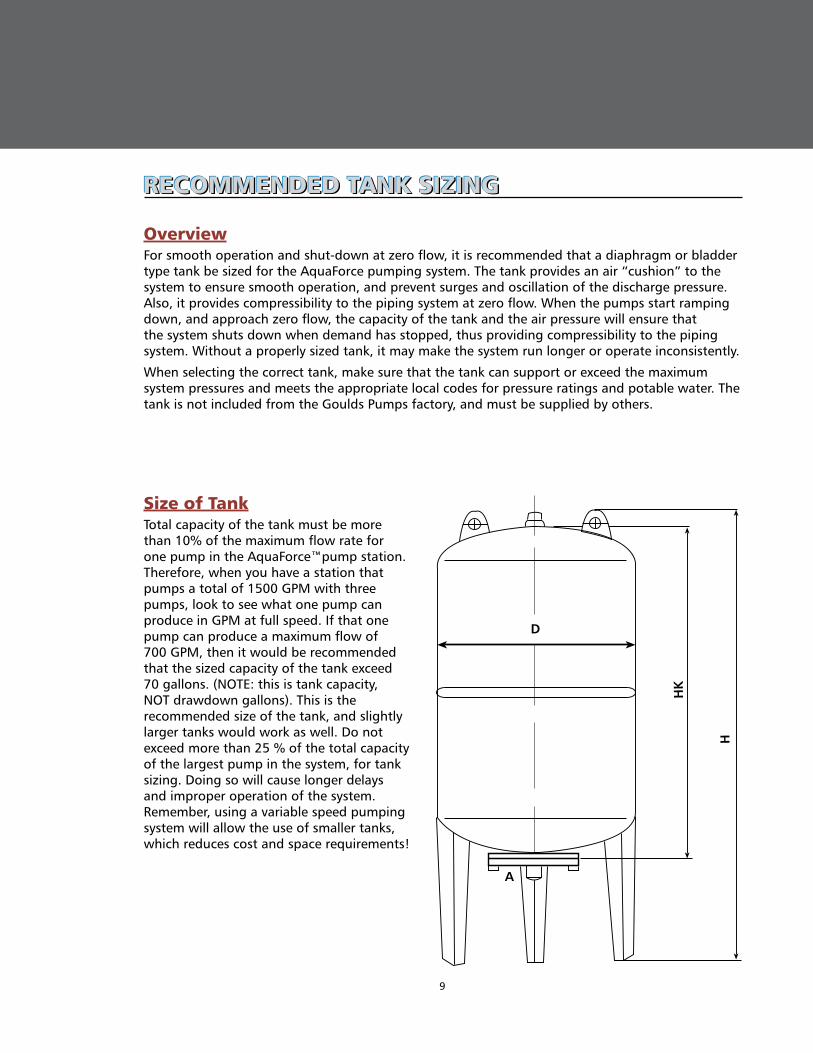
RECOMMENdEd TANK SIZINGRECOMMENdEd TANK SIZINGRECOMMENdEd TANK SIZING
OverviewFor smooth operation and shut-down at zero flow, it is recommended that a diaphragm or bladder type tank be sized for the AquaForce pumping system. The tank provides an air “cushion” to the system to ensure smooth operation, and prevent surges and oscillation of the discharge pressure. Also, it provides compressibility to the piping system at zero flow. When the pumps start ramping down, and approach zero flow, the capacity of the tank and the air pressure will ensure that the system shuts down when demand has stopped, thus providing compressibility to the piping system. Without a properly sized tank, it may make the system run longer or operate inconsistently.
When selecting the correct tank, make sure that the tank can support or exceed the maximum system pressures and meets the appropriate local codes for pressure ratings and potable water. The tank is not included from the Goulds Pumps factory, and must be supplied by others.
Size of TankTotal capacity of the tank must be more than 10% of the maximum flow rate for one pump in the AquaForce™pump station. Therefore, when you have a station that pumps a total of 1500 GPM with three pumps, look to see what one pump can produce in GPM at full speed. If that one pump can produce a maximum flow of 700 GPM, then it would be recommended that the sized capacity of the tank exceed 70 gallons. (NOTE: this is tank capacity, NOT drawdown gallons). This is the recommended size of the tank, and slightly larger tanks would work as well. Do not exceed more than 25 % of the total capacity of the largest pump in the system, for tank sizing. Doing so will cause longer delays and improper operation of the system. Remember, using a variable speed pumping system will allow the use of smaller tanks, which reduces cost and space requirements!
A
HK
H
D

10
Goulds PumpsAquaForce™ Pressure Boosting Sizing Guide
Tank PressureNow that the size (gallons) of the tank is determined, what pressure must be used in the tank? The tank should be pre-charged to approximately 10 – 12 psig below your system pressure. Therefore, if you had an AquaForce or Aquavar system, which was set to maintain 100 psig in your system, your tank would be charged to about 88 psig. Remember, that the tank is typically sent from the factory with little or no pressure, and a pre-charge will have to be performed at the site. When charging tanks, make sure that the maximum system pressure does not exceed the working pressure of the tank. For higher pressures, an ASME type tank may be needed for the system. Always follow tank manufacturers recommended procedures for pre-charge, mounting, piping. For accurate tank pressurization, be sure that there is no water in the system.
Tank LocationThe tank should be located in the discharge piping downstream from the check valves. When the check valves close, you should have the tank and the transducers between the check valve and your shut-off valves in your discharge system. Make sure that the tank connection is the full pipe size recommended for the connection. Do not reduce or connect “quick disconnect” couplings to the tank, which will impede the flow from the tank during system operation. If shut-off valves are used before the tank, make sure that they are open for operation and system testing. It is important to make sure that no valves or other devices are between the transducers and tank.
RECOMMENdEd TANK SIZINGRECOMMENdEd TANK SIZINGRECOMMENdEd TANK SIZING

11
AQuAVAR PuMP CONTROLAQuAVAR PuMP CONTROLAQuAVAR PuMP CONTROLThe AquaForce pump station comes complete with the Goulds Pumps Aquavar® or Aquavar II pump control mounted with each pump. The Aquavar is a pump specific variable speed controller which includes a control card, drive, communication circuit, transducer and pro-tection circuits in one compact package. It is completely self contained with only a circuit breaker required for full capability.
Although the Aquavar has broad program-ming capability for a wide range of pump applications the set up for your installation will be completed for you by your Goulds Pumps distributor or authorized contractor. Once complete, about the only thing you will need to learn is how to turn the units off and on, set the required pressure and view the error menu.
Each Aquavar has its own pressure transducer and is connected to the other Aquavars in the system via an RS485 connection. In operation, the Aquavar constantly compares the transduc-er reading from the discharge line to the re-quired pressure set point. When there is a drop in pressure, the Aquavar turns on the pump and gradually ramps up the motor speed until
the required pressure is being maintained. If the first pump reaches 60 Hz and the pressure is still not at the set point, a signal is automati-cally sent to the next Aquavar, which turns on the second pump. This continues until the set point is reached. If the set point is not reached with all pumps in operation (due to a broken discharge pipe for example) the Aquavars will automatically shut down after a time limit you select.
When there is reduced demand, the last pump to be started will gradually ramp down in speed and if pressure is still being maintained, will turn off. This will continue until all pumps are off in a no demand condition. This cyclic starting and stopping of the pumps based on user demand is completely automatic and assures consistent water pressure at varying flow rates. The Aquavar will also automatically change the lead pump at predetermined inter-vals to assure uniform pump use and wear. The following chart shows the pump speed and sequencing changes as demand increases at a set pressure requirement.
1 PUMP 2 PUMPS
PUMP START: controlled through the corresponding transducer once the minimumoperating value is reached.
PUMP STOP: controlled through the corresponding transducer once the maximumoperating value is reached.
FLOW
AquaForce
PPr
V
TDHOPERATING CURVES
PR = PRESSURE SET POINT P = UNIT DELIVERY PRESSURE
VARIATION RANGE V = PUMP SPEED
VARIATION RANGE
12
Goulds PumpsAquaForce™ Pressure Boosting Sizing Guide
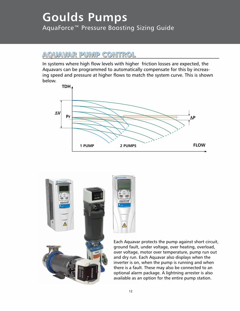
1 PUMP 2 PUMPS FLOW
PPrV
TDH
AQuAVAR PuMP CONTROLAQuAVAR PuMP CONTROLAQuAVAR PuMP CONTROLIn systems where high flow levels with higher friction losses are expected, the Aquavars can be programmed to automatically compensate for this by increas-ing speed and pressure at higher flows to match the system curve. This is shown below.
Each Aquavar protects the pump against short circuit, ground fault, under voltage, over heating, overload, over voltage, motor over temperature, pump run out and dry run. Each Aquavar also displays when the inverter is on, when the pump is running and when there is a fault. These may also be connected to an optional alarm package. A lightning arrester is also available as an option for the entire pump station.

13
AQuAVAR SELECTIONAQuAVAR SELECTIONAQuAVAR SELECTION
The AquaForce Pump Stations are available with either the space and cost saving pump mounted Aquavar or the panel configured Aquavar CPC. Use the following chart to determine which is best for your application.
Aquavar Pump Mount ✔ ✔ Aquavar CPC
Motor Size 230V / 1Ø 230V / 3Ø 460V / 3Ø
Up to 2 Hp –——> ✔ ✔ ✔ ✔ ✔
3 Hp ————> ✔ ✔ ✔ ✔ ✔
5 Hp ————> ✔ ✔ ✔ ✔ ✔ ✔
71⁄2 Hp ————> ✔ ✔ ✔ ✔ ✔ ✔
10 Hp ————> ✔ ✔ ✔ ✔ ✔ ✔
15 Hp ————> ✔ ✔ ✔
20 Hp ————> ✔ ✔ ✔
25 Hp ————> ✔ ✔
30 Hp ————> ✔ ✔
NOTE: Aquavar CPC is available up to 100 HP, 3Ø, 230V or 550 HP, 3Ø, 460V.
Aquavar CommunicationsThe following signals are available on each Aquavar as standard equipment:
• RS485 - signal to other Aquavars or optional modbus interface.• Pump running signal - dry contact.• Fault signal - dry contact.• Current pressure reading or running frequency - 0-10V analog.• Connection for remote on/off.• Multiple digital inputs.• Analog outputs.
As listed, a modbus interface is available for the Aquavar. On the AquaForce station, one interface card communicates to all pumps.
For more specific information on the Aquavar or Aquavar CPC products, please refer to the Goulds Pumps bulletin, GLAQUA2.
14
Goulds PumpsAquaForce™ Pressure Boosting Sizing Guide
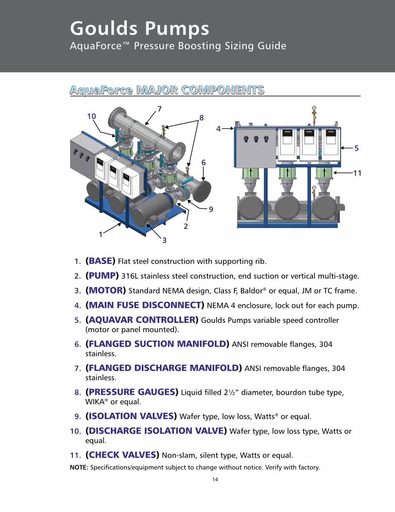
AquaForce MAJOR COMPONENTSAquaForce MAJOR COMPONENTSAquaForce MAJOR COMPONENTS
1. (BASE) Flat steel construction with supporting rib.
2. (PuMP) 316L stainless steel construction, end suction or vertical multi-stage.
3. (MOTOR) Standard NEMA design, Class F, Baldor® or equal, JM or TC frame.
4. (MAIN FuSE dISCONNECT) NEMA 4 enclosure, lock out for each pump.
5. (AQuAVAR CONTROLLER) Goulds Pumps variable speed controller (motor or panel mounted).
6. (FLANGEd SuCTION MANIFOLd) ANSI removable flanges, 304 stainless.
7. (FLANGEd dISCHARGE MANIFOLd) ANSI removable flanges, 304 stainless.
8. (PRESSuRE GAuGES) Liquid filled 2½” diameter, bourdon tube type, WIKA® or equal.
9. (ISOLATION VALVES) Wafer type, low loss, Watts® or equal.
10. (dISCHARGE ISOLATION VALVE) Wafer type, low loss type, Watts or equal.
11. (CHECK VALVES) Non-slam, silent type, Watts or equal.NOTE: Specifications/equipment subject to change without notice. Verify with factory.
13
2
9
6
87
10
4
5
11
15
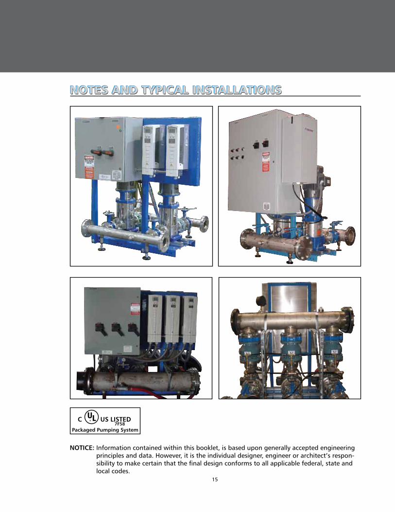
NOTES ANd TyPICAL INSTALLATIONSNOTES ANd TyPICAL INSTALLATIONSNOTES ANd TyPICAL INSTALLATIONS
NOTICE: Information contained within this booklet, is based upon generally accepted engineering principles and data. However, it is the individual designer, engineer or architect’s respon-sibility to make certain that the final design conforms to all applicable federal, state and local codes.
UL® C US LISTED 7F58Packaged Pumping System

AquaForce FEATuRES ANd SPECIFICATIONSAquaForce FEATuRES ANd SPECIFICATIONSAquaForce FEATuRES ANd SPECIFICATIONS➾ Ambient temperatures up to 120º F.
➾ Maximum operating pressures up to 200 psi.
➾ Pump run-out protection.
➾ Dry running protection.
➾ Programmable lead/ lag alternation.
➾ Programmable system curve/ friction loss compensation.
➾ Programmable system pressure starting.
➾ Fault detection and alarms relay.
➾ Motor run relay.
➾ Programmable soft start.
➾ 304 Stainless steel piping.
➾ Bronze-fitted, isolation valves.
➾ Optional suction / low pressure switch.
➾ Optional pressure relief valves and temperature relief valves.
➾ Optional lightning protection.
➾ Optional flexible discharge hose.
➾ All systems are UL rated and run tested.
➾ Maximum footprint, on most sizes, allow systems to fit through standard doorways.
➾ 200 – 230 Volt single phase 1 – 10 HP, 200 – 230 Volt three phase 1 – 20 HP, 460 Volt 1 – 30 HP.
➾ Each system is fabricated with Goulds Pumps horizontal or vertical multi-stage stainless and cast iron centrifugal pumps with a variety of electrical and mechanical options to choose from.
➾ Standard “off the shelf“ motors by Baldor or USEM Motors.
➾ Significant reduction in energy consumption over fixed speed systems.
➾ System protection from overvoltage, under-voltage, blocked suction, cavitation, NPSHa, phase loss, short circuit, transducer failure, and motor overload.
➾ Liquid temperatures up to 212º F.
Wastewater
ITTEngineered for life
Copyright © 2009 ITT Corporation BRAQFOR July, 2009 Printed in U.S.A.SPECIFICATIONS ARE SUBJECT TO CHANGE WITHOUT NOTICE.
ITT 2881 East Bayard Street Seneca Falls, NY 13148 Phone: (315) 568-7123 Fax: (315) 568-7973
www.goulds.com
Goulds Pumps, Aquavar, AquaBoost and AquaForce are registered trademarks of ITT Corporation. ITT, the Engineered Blocks Symbol and Engineered for Life are registered trademarks of ITT Manufacturing Enterprises, Inc.WIKA is a registered trademark of WIKA Instrument Corporation. WATTS Regulator is a registered trademark of WATTS Industry Incorporated.Baldor is a registered trademark of Baldor Electric Company.