APT: Accurate Outdoor Pedestrian Tracking with …liqun/paper/infocom13_1.pdfa smartphone and a...
9
APT: Accurate Outdoor Pedestrian Tracking with Smartphones Xiaojun Zhu *† , Qun Li † , Guihai Chen *§ * State Key Laboratory for Novel Software Technology, Nanjing University, Nanjing 210024, China † Department of Computer Science, the College of William and Mary, Williamsburg, VA 23185, USA § Shanghai Key Laboratory of Scalable Computing and Systems, Shanghai Jiao Tong University, Shanghai 200240, China Email: [email protected], [email protected], [email protected] Abstract—This paper presents APT, a localization system for outdoor pedestrians with smartphones. APT performs better than the built-in GPS module of the smartphone in terms of accuracy. This is achieved by introducing a robust dead reckoning algorithm and an error-tolerant algorithm for map matching. When the user is walking with the smartphone, the dead reckoning algorithm monitors steps and walking direction in real time. It then reports new steps and turns to the map- matching algorithm. Based on updated information, this algo- rithm adjusts the user’s location on a map in an error-tolerant manner. If location ambiguity among several routes occurs after adjustments, the GPS module is queried to help eliminate this ambiguity. Evaluations in practice show that the error of our system is less than 1/2 that of GPS. I. I NTRODUCTION We have noticed several occurrences of blind people losing their way in our university. It is disconcerting to see those visually impaired people disoriented on campus even though the routes are comparably familiar and thus simple to follow. We realize that the fundamental reason why blind people lose their way is that they do not know their current location and easily miss a turn or go toward a wrong direction. We aim to build a system to assist the blind people with smartphones by providing accurate location information and, combined with a digital map, offering guidance audio messages. Compared with blind navigation systems such as RFID based technology, it is our belief that this system can be rapidly and inexpensively deployed. Toward this goal, this paper solves the localization problem by designing an accurate outdoor pedestrian tracking system. GPS, the most accurate localization service for smart- phones at present, has inherent limitations in its accuracy. Our GPS measurements show error up to 15 meters in a clear-sky- view environment and up to 20 meters when trees are around. Such accuracy restricts the development of our system. Our goal is to improve localization accuracy to a few meter- s. This touches the fundamental limitation of GPS and enables accuracy-demanding applications. To improve the accuracy of the GPS module on smartphones, we tried several approaches including taking the average for consecutive GPS readings and consulting GPS location history data. Unfortunately, the improvement is negligible. The underlying reason is that GPS error does not have a useful pattern. It can be arbitrary from time to time and from location to location. The work was done when the first author was visiting the College of William and Mary. To realize our goal, we base our solution on three observa- tions. First, pedestrians have regular movements that provide opportunities for an accurate dead reckoning system. Second, though the accuracy of GPS is unsatisfactory, it works well in distinguishing between distant routes. Third, we can easily generate augmented maps on a smartphone. Based on these observations, we design a dead reckoning algorithm and a map- matching algorithm. The dead reckoning algorithm detects steps and turns, and triggers our map-matching algorithm. When map-matching fails to uniquely determine a route, it requests location information from the GPS component. The main purpose of GPS is to help distinguish between distant routes, thus GPS is requested infrequently. Consequently, the increased energy efficiency is another advantage of our system (the accelerometer and gyroscope are known to consume much less energy than GPS [1]). However, there are various challenges in implementing the ideas above, such as different phone placements, phone axes reorientation and error-tolerant map-matching. Tackling these challenges constitutes our con- tributions, which can be enumerated as follows. First, we propose a robust dead reckoning algorithm (Sec- tion V). This algorithm features two designs. First, instead of detecting walking steps as usual, we manage to find accel- eration patterns that can reflect travel distance and be easily detected. This design simplifies the detection problem, and the resulting algorithm can also tolerate different placement of the phone. Second, we do not require the user to hold the phone flat out when using the system. Usually, this requirement is for walking direction estimation. We relax this requirement by re-orienting the phone’s axes robustly so that different ways to hold the phone yield the same direction estimation. Second, we propose an error-tolerant map-matching algo- rithm (Section VI). The novelty is that it tolerates possible errors of the dead reckoning algorithm and GPS. This tolerance is achieved by trying all possible routes that are within our error tolerance threshold. In some cases, this scheme finds sev- eral possible routes and cannot determine which one is correct. Then, GPS can be used to help eliminate this ambiguity. Third, we evaluate our approach using real-world measure- ments conducted around the campus (Section VII). The results show that our approach can achieve a localization accuracy within 5 meters, while GPS-based solutions have error up to 15 meters. The rest of this paper is organized as follows. We review related works in Section II, and report GPS observations
Transcript of APT: Accurate Outdoor Pedestrian Tracking with …liqun/paper/infocom13_1.pdfa smartphone and a...
APT: Accurate Outdoor Pedestrian Tracking withSmartphones
Xiaojun Zhu∗†, Qun Li†, Guihai Chen∗§∗State Key Laboratory for Novel Software Technology, Nanjing University, Nanjing 210024, China†Department of Computer Science, the College of William and Mary, Williamsburg, VA 23185, USA
§Shanghai Key Laboratory of Scalable Computing and Systems, Shanghai Jiao Tong University, Shanghai 200240, ChinaEmail: [email protected], [email protected], [email protected]
Abstract—This paper presents APT, a localization system foroutdoor pedestrians with smartphones. APT performs betterthan the built-in GPS module of the smartphone in termsof accuracy. This is achieved by introducing a robust deadreckoning algorithm and an error-tolerant algorithm for mapmatching. When the user is walking with the smartphone, thedead reckoning algorithm monitors steps and walking directionin real time. It then reports new steps and turns to the map-matching algorithm. Based on updated information, this algo-rithm adjusts the user’s location on a map in an error-tolerantmanner. If location ambiguity among several routes occurs afteradjustments, the GPS module is queried to help eliminate thisambiguity. Evaluations in practice show that the error of oursystem is less than 1/2 that of GPS.
I. INTRODUCTION
We have noticed several occurrences of blind people losingtheir way in our university. It is disconcerting to see thosevisually impaired people disoriented on campus even thoughthe routes are comparably familiar and thus simple to follow.We realize that the fundamental reason why blind people losetheir way is that they do not know their current location andeasily miss a turn or go toward a wrong direction. We aim tobuild a system to assist the blind people with smartphones byproviding accurate location information and, combined with adigital map, offering guidance audio messages. Compared withblind navigation systems such as RFID based technology, it isour belief that this system can be rapidly and inexpensivelydeployed. Toward this goal, this paper solves the localizationproblem by designing an accurate outdoor pedestrian trackingsystem.
GPS, the most accurate localization service for smart-phones at present, has inherent limitations in its accuracy. OurGPS measurements show error up to 15 meters in a clear-sky-view environment and up to 20 meters when trees are around.Such accuracy restricts the development of our system.
Our goal is to improve localization accuracy to a few meter-s. This touches the fundamental limitation of GPS and enablesaccuracy-demanding applications. To improve the accuracy ofthe GPS module on smartphones, we tried several approachesincluding taking the average for consecutive GPS readingsand consulting GPS location history data. Unfortunately, theimprovement is negligible. The underlying reason is that GPSerror does not have a useful pattern. It can be arbitrary fromtime to time and from location to location.
The work was done when the first author was visiting the College of Williamand Mary.
To realize our goal, we base our solution on three observa-tions. First, pedestrians have regular movements that provideopportunities for an accurate dead reckoning system. Second,though the accuracy of GPS is unsatisfactory, it works wellin distinguishing between distant routes. Third, we can easilygenerate augmented maps on a smartphone. Based on theseobservations, we design a dead reckoning algorithm and a map-matching algorithm. The dead reckoning algorithm detectssteps and turns, and triggers our map-matching algorithm.When map-matching fails to uniquely determine a route, itrequests location information from the GPS component. Themain purpose of GPS is to help distinguish between distantroutes, thus GPS is requested infrequently. Consequently, theincreased energy efficiency is another advantage of our system(the accelerometer and gyroscope are known to consumemuch less energy than GPS [1]). However, there are variouschallenges in implementing the ideas above, such as differentphone placements, phone axes reorientation and error-tolerantmap-matching. Tackling these challenges constitutes our con-tributions, which can be enumerated as follows.
First, we propose a robust dead reckoning algorithm (Sec-tion V). This algorithm features two designs. First, instead ofdetecting walking steps as usual, we manage to find accel-eration patterns that can reflect travel distance and be easilydetected. This design simplifies the detection problem, and theresulting algorithm can also tolerate different placement of thephone. Second, we do not require the user to hold the phoneflat out when using the system. Usually, this requirement isfor walking direction estimation. We relax this requirement byre-orienting the phone’s axes robustly so that different waysto hold the phone yield the same direction estimation.
Second, we propose an error-tolerant map-matching algo-rithm (Section VI). The novelty is that it tolerates possibleerrors of the dead reckoning algorithm and GPS. This toleranceis achieved by trying all possible routes that are within ourerror tolerance threshold. In some cases, this scheme finds sev-eral possible routes and cannot determine which one is correct.Then, GPS can be used to help eliminate this ambiguity.
Third, we evaluate our approach using real-world measure-ments conducted around the campus (Section VII). The resultsshow that our approach can achieve a localization accuracywithin 5 meters, while GPS-based solutions have error up to15 meters.
The rest of this paper is organized as follows. We reviewrelated works in Section II, and report GPS observations
in Section III. Section IV overviews our solution, followedby detailed description of the dead reckoning algorithm inSection V and the map matching algorithm in Section VI. Weconduct evaluation in Section VII, discuss related issues inSection VIII and conclude our paper in Section IX.
II. RELATED WORKS
Many indoor localization systems can achieve localizationaccuracy to within a few meters. Radar [2] is a classicindoor localization system using wireless signal fingerprintingto localize a user. It requires a training period that incurslabor-intensive data collection. Recently, researchers try toeliminate this training period by solving a system of equationsto find the wireless propagation model [3]. SparseTrack [4]is an indoor pedestrian tracking system, where a user carriesa smartphone and a special sensor mote (Cricket mote). Thesmartphone is for dead reckoning where the accelerometer andthe digital compass are for distance estimation and directionestimation respectively. The error accumulation problem ofthe dead reckoning system is tackled by the special sensormote, which has ultrasound ranging capability and can com-municate with other sparsely deployed special sensor motesin the infrastructure. Our dead reckoning system differs in thetype of sensors used and in the techniques. Additionally, theerror accumulation problem in our system is solved by themap-matching component. Localization is also an importantresearch problem in wireless sensor networks [5]–[8].
Smartphones have become pervasive in the past severalyears. Among the numerous applications for smartphones,many require position information [9]–[11]. For these applica-tions, GPS is the most popular choice, but it is power-hungry.Much research effort has been devoted to improving the energyefficiency issue of GPS [12]–[18]. One common approach isto substitute power-hungry GPS with energy-efficient local-ization schemes such as WiFi and cellular-tower. Followingthis idea, EnTracked [14] focuses on position tracking, andEnTrackedT [16] focuses on trajectory tracking. A-Loc [12]tries to track positions for mobile search applications withdynamic accuracy. RAPS [15] turns on GPS in a rate-adaptivemanner. CAPS [13] is a cell-ID based positioning systemthat leverages position history for localization. If multipleapplications request location service simultaneously, then aunifying middleware layer can help reduce the use of GPS [17].Another idea for saving energy is to modify GPS in hardware.LEAP [18] shifts the position calculating step of the GPShardware to the cloud, providing energy efficient trajectoryservice. Other localization methods are also proposed forsmartphones. EV-Loc [19] integrates electronic and visualsignal for accurate localization and tracking. E-Shadow [20]has a localization component using direction information.
Several works consider off-line localization. AutoWit-ness [21] is a system for tracking stolen personal property.In the system, a special tag is embedded inside an asset to beprotected. The tag contains an accelerometer and a gyroscopefor dead reckoning, and a GSM/GPRS model for reporting datato a server. The server performs map-matching to recover thetraveled route. We differ in both the dead reckoning system andthe map-matching algorithm. First, our dead reckoning systemis designed specifically for pedestrians, and theirs is for cars.The solutions are not applicable to each other due to different
movement properties. Second, we focus on online tracking,while the off-line map-matching algorithm in AutoWitnesscannot be easily extended to this scenario. Another workconsiders utilizing temporal stability and low-rank structurefor improving localization accuracy [22].
III. ERROR CHARACTERISTICS OF SMARTPHONE GPS
We consider improving GPS accuracy based solely on GPS.This requires the knowledge of GPS error characteristics. Forthis purpose, we conducted GPS measurements around SunkenGarden, Williamsburg, VA (N37.270851◦,W76.711682◦). Thesmartphone we use is the Samsung Galaxy S II on the androidplatform. It is programmed to collect GPS data once a second.Our first encountered issue is that at any location, if the GPScoordinate stabilizes, then it will never change, or will notchange for at least several hours. Experiments with differentphones, locations and durations all lead to the same result.One possible explanation is that this is a strategy of the GPShardware and/or Android system for saving energy. But thisphenomenon implies that staying in one place longer does nothelp improve GPS accuracy. Thus, the natural and seeminglypossible solution, staying in a place and taking the average ofall GPS readings, will not work well in practice. Finally, weresort to the following strategy for data collection. Every timethe readings stabilize, we change the phone’s location briefly.Among the measurements we conducted, we report two typicalones.
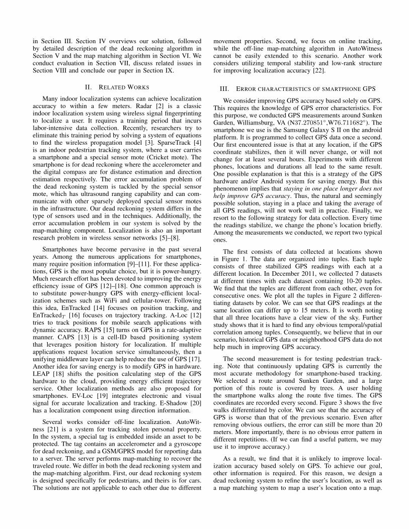
The first consists of data collected at locations shownin Figure 1. The data are organized into tuples. Each tupleconsists of three stabilized GPS readings with each at adifferent location. In December 2011, we collected 7 datasetsat different times with each dataset containing 10-20 tuples.We find that the tuples are different from each other, even forconsecutive ones. We plot all the tuples in Figure 2 differen-tiating datasets by color. We can see that GPS readings at thesame location can differ up to 15 meters. It is worth notingthat all three locations have a clear view of the sky. Furtherstudy shows that it is hard to find any obvious temporal/spatialcorrelation among tuples. Consequently, we believe that in ourscenario, historical GPS data or neighborhood GPS data do nothelp much in improving GPS accuracy.
The second measurement is for testing pedestrian track-ing. Note that continuously updating GPS is currently themost accurate methodology for smartphone-based tracking.We selected a route around Sunken Garden, and a largeportion of this route is covered by trees. A user holdingthe smartphone walks along the route five times. The GPScoordinates are recorded every second. Figure 3 shows the fivewalks differentiated by color. We can see that the accuracy ofGPS is worse than that of the previous scenario. Even afterremoving obvious outliers, the error can still be more than 20meters. More importantly, there is no obvious error pattern indifferent repetitions. (If we can find a useful pattern, we mayuse it to improve accuracy.)
As a result, we find that it is unlikely to improve local-ization accuracy based solely on GPS. To achieve our goal,other information is required. For this reason, we design adead reckoning system to refine the user’s location, as well asa map matching system to map a user’s location onto a map.
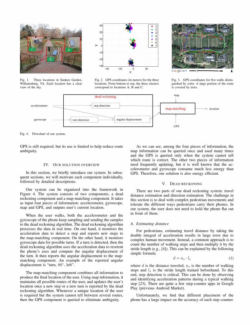
Fig. 1. Three locations in Sunken Garden,Williamsburg, VA. Each location has a clearview of the sky.
−40 −20 0 20−30
−20
−10
0
10
20
30
x
y
1234567
Fig. 2. GPS coordinates (in meters) for the threelocations. From bottom to top, the three clusterscorrespond to locations A, B and C.
Fig. 3. GPS coordinates for five walks distin-guished by color. A large portion of the routeis covered by trees.
step detection
turn detection angular displacement
accelerometer
gyroscope
dead reckoning map
GPS
locationmap-matching
Fig. 4. Flowchart of our system.
GPS is still required, but its use is limited to help reduce routeambiguity.
IV. OUR SOLUTION OVERVIEW
In this section, we briefly introduce our system. In subse-quent sections, we will motivate each component individually,followed by detailed descriptions.
Our system can be organized into the framework inFigure 4. The system consists of two components, a deadreckoning component and a map-matching component. It takesas input four pieces of information: accelerometer, gyroscope,map and GPS, and outputs user’s current location.
When the user walks, both the accelerometer and thegyroscope of the phone keep sampling and sending the samplesto the dead reckoning algorithm. The dead reckoning algorithmprocesses the data in real time. On one hand, it monitors theacceleration data to detect a step and reports new steps tothe map-matching component. On the other hand, it monitorsgyroscope data for possible turns. If a turn is detected, then thedead reckoning algorithm uses the acceleration data to reorientthe phone’s axes and compute the angular displacement ofthe turn. It then reports the angular displacement to the map-matching component. An example of the reported angulardisplacement is “turn, 80◦, left”.
The map-matching component combines all information toproduce the final location of the user. Using map information, itmaintains all possible routes of the user, and updates the user’slocation once a new step or a new turn is reported by the deadreckoning algorithm. Whenever a unique location of the useris required but the system cannot tell between several routes,then the GPS component is queried to eliminate ambiguity.
As we can see, among the four pieces of information, themap information can be queried once and used many timesand the GPS is queried only when the system cannot tellwhich route is correct. The other two pieces of informationneed frequently updating, but it is well known that the ac-celerometer and gyroscope consume much less energy thanGPS. Therefore, our solution is also energy efficient.
V. DEAD RECKONING
There are two parts of our dead reckoning system: traveldistance estimation and direction estimation. The challenge inthis section is to deal with complex pedestrian movements andtolerate the different ways pedestrians carry their phones. Inour system, the user does not need to hold the phone flat outin front of them.
A. Estimating distance
For pedestrians, estimating travel distance by taking thedouble integral of acceleration results in large error due tocomplex human movement. Instead, a common approach is tocount the number of walking steps and then multiply it by thestride length (e.g., [4]). This can be explained by the followingsimple formula
d = ns · ls (1)
where d is the distance traveled, ns is the number of walkingsteps and ls is the stride length trained beforehand. To thisend, step detection is critical. This can be done by observingand identifying acceleration patterns during a typical walkingstep [23]. There are quite a few step-counter apps in GooglePlay (previous Android Market).
Unfortunately, we find that different placement of thephone has a large impact on the accuracy of each step counter.
32 33 34 35 360
5
10
15
20
25
time (second)
mag
nitu
de
handpocket
(a) Acceleration magnitude
32 33 34 35 36−30
−20
−10
0
10
20
30
40
time (second)
degr
ee p
er s
econ
d
xyz
(b) Gyroscope readings
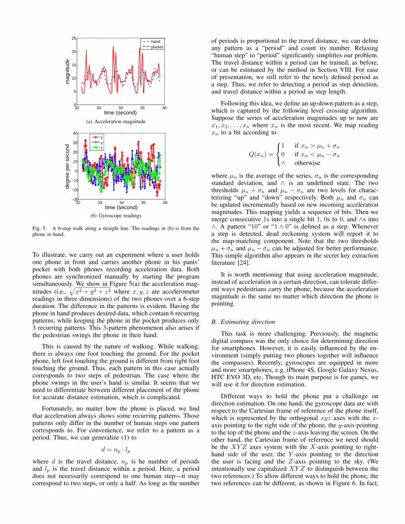
Fig. 5. A 6-step walk along a straight line. The readings in (b) is from thephone in hand.
To illustrate, we carry out an experiment where a user holdsone phone in front and carries another phone in his pants’pocket with both phones recording acceleration data. Bothphones are synchronized manually by starting the programsimultaneously. We show in Figure 5(a) the acceleration mag-nitudes (i.e.,
√x2 + y2 + z2 where x, y, z are accelerometer
readings in three dimensions) of the two phones over a 6-stepduration. The difference in the patterns is evident. Having thephone in hand produces desired data, which contain 6 recurringpatterns; while keeping the phone in the pocket produces only3 recurring patterns. This 3-pattern phenomenon also arises ifthe pedestrian swings the phone in their hand.
This is caused by the nature of walking. While walking,there is always one foot touching the ground. For the pocketphone, left foot touching the ground is different from right foottouching the ground. Thus, each pattern in this case actuallycorresponds to two steps of pedestrian. The case where thephone swings in the user’s hand is similar. It seems that weneed to differentiate between different placement of the phonefor accurate distance estimation, which is complicated.
Fortunately, no matter how the phone is placed, we findthat acceleration always shows some recurring patterns. Thosepatterns only differ in the number of human steps one patterncorresponds to. For convenience, we refer to a pattern as aperiod. Thus, we can generalize (1) to
d = np · lpwhere d is the travel distance, np is he number of periodsand lp is the travel distance within a period. Here, a perioddoes not necessarily correspond to one human step—it maycorrespond to two steps, or only a half. As long as the number
of periods is proportional to the travel distance, we can defineany pattern as a “period” and count its number. Relaxing“human step” to “period” significantly simplifies our problem.The travel distance within a period can be trained, as before,or can be estimated by the method in Section VIII. For easeof presentation, we still refer to the newly defined period asa step. Thus, we refer to detecting a period as step detection,and travel distance within a period as step length.
Following this idea, we define an up-down pattern as a step,which is captured by the following level crossing algorithm.Suppose the series of acceleration magnitudes up to now arex1, x2, . . . , xn where xn is the most recent. We map readingxn to a bit according to
Q(xn) =
1 if xn > µn + σn0 if xn < µn − σn∧ otherwise
where µn is the average of the series, σn is the correspondingstandard deviation, and ∧ is an undefined state. The twothresholds µn + σn and µn − σn are two levels for charac-terizing “up” and “down” respectively. Both µn and σn canbe updated incrementally based on new incoming accelerationmagnitudes. This mapping yields a sequence of bits. Then wemerge consecutive 1s into a single bit 1, 0s to 0, and ∧s into∧. A pattern “10” or “1 ∧ 0” is defined as a step. Whenevera step is detected, dead reckoning system will report it tothe map-matching component. Note that the two thresholdsµn + σn and µn − σn can be adjusted for better performance.This simple algorithm also appears in the secret key extractionliterature [24].
It is worth mentioning that using acceleration magnitude,instead of acceleration in a certain direction, can tolerate differ-ent ways pedestrians carry the phone, because the accelerationmagnitude is the same no matter which direction the phone ispointing.
B. Estimating direction
This task is more challenging. Previously, the magneticdigital compass was the only choice for determining directionfor smartphones. However, it is easily influenced by the en-vironment (simply putting two phones together will influencethe compasses). Recently, gyroscopes are equipped in moreand more smartphones, e.g, iPhone 4S, Google Galaxy Nexus,HTC EVO 3D, etc. Though its main purpose is for games, wewill use it for direction estimation.
Different ways to hold the phone put a challenge ondirection estimation. On one hand, the gyroscope data are withrespect to the Cartesian frame of reference of the phone itself,which is represented by the orthogonal xyz axes with the x-axis pointing to the right side of the phone, the y-axis pointingto the top of the phone and the z-axis leaving the screen. On theother hand, the Cartesian frame of reference we need shouldbe the XY Z axes system with the X-axis pointing to right-hand side of the user, the Y -axis pointing to the directionthe user is facing and the Z-axis pointing to the sky. (Weintentionally use capitalized XY Z to distinguish between thetwo references.) To allow different ways to hold the phone, thetwo references can be different, as shown in Figure 6. In fact,
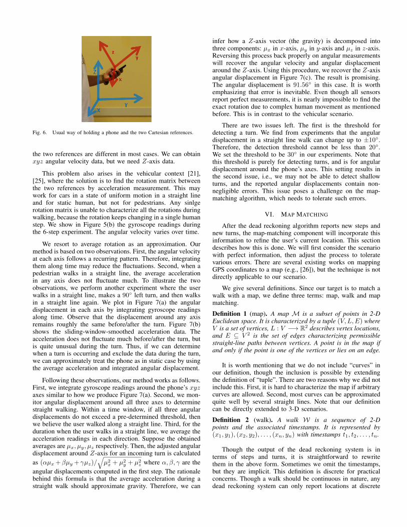
Fig. 6. Usual way of holding a phone and the two Cartesian references.
the two references are different in most cases. We can obtainxyz angular velocity data, but we need Z-axis data.
This problem also arises in the vehicular context [21],[25], where the solution is to find the rotation matrix betweenthe two references by acceleration measurement. This maywork for cars in a state of uniform motion in a straight lineand for static human, but not for pedestrians. Any sinlgerotation matrix is unable to characterize all the rotations duringwalking, because the rotation keeps changing in a single humanstep. We show in Figure 5(b) the gyroscope readings duringthe 6-step experiment. The angular velocity varies over time.
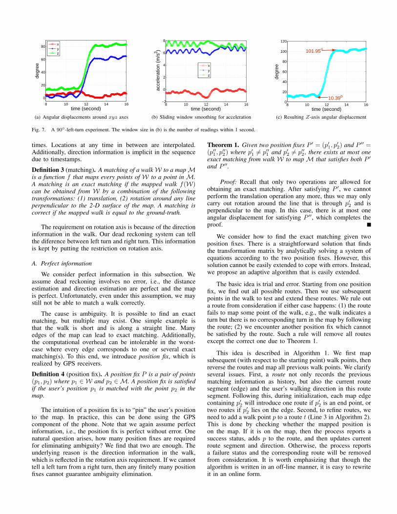
We resort to average rotation as an approximation. Ourmethod is based on two observations. First, the angular velocityat each axis follows a recurring pattern. Therefore, integratingthem along time may reduce the fluctuations. Second, when apedestrian walks in a straight line, the average accelerationin any axis does not fluctuate much. To illustrate the twoobservations, we perform another experiment where the userwalks in a straight line, makes a 90◦ left turn, and then walksin a straight line again. We plot in Figure 7(a) the angulardisplacement in each axis by integrating gyroscope readingsalong time. Observe that the displacement around any axisremains roughly the same before/after the turn. Figure 7(b)shows the sliding-window-smoothed acceleration data. Theacceleration does not fluctuate much before/after the turn, butis quite unusual during the turn. Thus, if we can determinewhen a turn is occurring and exclude the data during the turn,we can approximately treat the phone as in static case by usingthe average acceleration and integrated angular displacement.
Following these observations, our method works as follows.First, we integrate gyroscope readings around the phone’s xyzaxes similar to how we produce Figure 7(a). Second, we mon-itor angular displacement around all three axes to determinestraight walking. Within a time window, if all three angulardisplacements do not exceed a pre-determined threshold, thenwe believe the user walked along a straight line. Third, for theduration when the user walks in a straight line, we average theacceleration readings in each direction. Suppose the obtainedaverages are µx, µy, µz respectively. Then, the adjusted angulardisplacement around Z-axis for an incoming turn is calculatedas (αµx +βµy + γµz)/
√µ2x + µ2
y + µ2z where α, β, γ are the
angular displacements computed in the first step. The rationalebehind this formula is that the average acceleration during astraight walk should approximate gravity. Therefore, we can
infer how a Z-axis vector (the gravity) is decomposed intothree components: µx in x-axis, µy in y-axis and µz in z-axis.Reversing this process back properly on angular measurementswill recover the angular velocity and angular displacementaround the Z-axis. Using this procedure, we recover the Z-axisangular displacement in Figure 7(c). The result is promising.The angular displacement is 91.56◦ in this case. It is worthemphasizing that error is inevitable. Even though all sensorsreport perfect measurements, it is nearly impossible to find theexact rotation due to complex human movement as mentionedbefore. This is in contrast to the vehicular scenario.
There are two issues left. The first is the threshold fordetecting a turn. We find from experiments that the angulardisplacement in a straight line walk can change up to ±10◦.Therefore, the detection threshold cannot be less than 20◦.We set the threshold to be 30◦ in our experiments. Note thatthis threshold is purely for detecting turns, and is for angulardisplacement around the phone’s axes. This setting results inthe second issue, i.e., we may not be able to detect shallowturns, and the reported angular displacements contain non-negligible errors. This issue poses a challenge on the map-matching algorithm, which needs to tolerate such errors.
VI. MAP MATCHING
After the dead reckoning algorithm reports new steps andnew turns, the map-matching component will incorporate thisinformation to refine the user’s current location. This sectiondescribes how this is done. We will first consider the scenariowith perfect information, then adjust the process to toleratevarious errors. There are several existing works on mappingGPS coordinates to a map (e.g., [26]), but the technique is notdirectly applicable to our scenario.
We give several definitions. Since our target is to match awalk with a map, we define three terms: map, walk and mapmatching.
Definition 1 (map). A map M is a subset of points in 2-DEuclidean space. It is characterized by a tuple (V,L,E) whereV is a set of vertices, L : V −→ R2 describes vertex locations,and E ⊆ V 2 is the set of edges characterizing permissiblestraight-line paths between vertices. A point is in the map ifand only if the point is one of the vertices or lies on an edge.
It is worth mentioning that we do not include “curves” inour definition, though the inclusion is possible by extendingthe definition of “tuple”. There are two reasons why we did notinclude this. First, it is hard to characterize the map if arbitrarycurves are allowed. Second, most curves can be approximatedquite well by several straight lines. Note that our definitioncan be directly extended to 3-D scenarios.
Definition 2 (walk). A walk W is a sequence of 2-Dpoints and the associated timestamps. It is represented by(x1, y1), (x2, y2), . . . , (xn, yn) with timestamps t1, t2, . . . , tn.
Though the output of the dead reckoning system is interms of steps and turns, it is straightforward to rewritethem in the above form. Sometimes we omit the timestamps,but they are implicit. This definition is discrete for practicalconcerns. Though a walk should be continuous in nature, anydead reckoning system can only report locations at discrete
8 10 12 14 16
0
20
40
60
80
time (second)
degr
ee
xyz
(a) Angular displacements around xyz axes
8 10 12 14 16−2
0
2
4
6
8
time (second)
acce
lera
tion
(m/s
2 )
xyz
(b) Sliding window smoothing for acceleration
8 10 12 14 160
20
40
60
80
100
120
time (second)
degr
ee
10.39o
101.95o
(c) Resulting Z-axis angular displacement
Fig. 7. A 90◦-left-turn experiment. The window size in (b) is the number of readings within 1 second.
times. Locations at any time in between are interpolated.Additionally, direction information is implicit in the sequencedue to timestamps.
Definition 3 (matching). A matching of a walkW to a mapMis a function f that maps every points of W to a point in M.A matching is an exact matching if the mapped walk f(W)can be obtained from W by a combination of the followingtransformations: (1) translation, (2) rotation around any lineperpendicular to the 2-D surface of the map. A matching iscorrect if the mapped walk is equal to the ground-truth.
The requirement on rotation axis is because of the directioninformation in the walk. Our dead reckoning system can tellthe diference between left turn and right turn. This informationis kept by putting the restriction on rotation axis.
A. Perfect information
We consider perfect information in this subsection. Weassume dead reckoning involves no error, i.e., the distanceestimation and direction estimation are perfect and the mapis perfect. Unfortunately, even under this assumption, we maystill not be able to match a walk correctly.
The cause is ambiguity. It is possible to find an exactmatching, but multiple may exist. One simple example isthat the walk is short and is along a straight line. Manyedges of the map can lead to exact matching. Additionally,the computational overhead can be intolerable in the worst-case where every edge corresponds to one or several exactmatching(s). To this end, we introduce position fix, which isrealized by GPS receivers.
Definition 4 (position fix). A position fix P is a pair of points(p1, p2) where p1 ∈ W and p2 ∈M. A position fix is satisfiedif the user’s position p1 is matched with the point p2 in themap.
The intuition of a position fix is to “pin” the user’s positionto the map. In practice, this can be done using the GPScomponent of the phone. Note that we again assume perfectinformation, i.e., the position fix is perfect without error. Onenatural question arises, how many position fixes are requiredfor eliminating ambiguity? We find that two are enough. Theunderlying reason is the direction information in the walk,which is reflected in the rotation axis requirement. If we cannottell a left turn from a right turn, then any finitely many positionfixes cannot guarantee ambiguity elimination.
Theorem 1. Given two position fixes P ′ = (p′1, p′2) and P ′′ =
(p′′1 , p′′2) where p′1 6= p′′1 and p′2 6= p′′2 , there exists at most one
exact matching from walk W to map M that satisfies both P ′and P ′′.
Proof: Recall that only two operations are allowed forobtaining an exact matching. After satisfying P ′, we cannotperform the translation operation any more, thus we may onlycarry out rotation around the line that is through p′2 and isperpendicular to the map. In this case, there is at most oneangular displacement for satisfying P ′′, which completes theproof.
We consider how to find the exact matching given twoposition fixes. There is a straightforward solution that findsthe transformation matrix by analytically solving a system ofequations according to the two position fixes. However, thissolution cannot be easily extended to cope with errors. Instead,we propose an adaptive algorithm that is easily extended.
The basic idea is trial and error. Starting from one positionfix, we find out all possible routes. Then we use subsequentpoints in the walk to test and extend these routes. We rule outa route from consideration if either case happens: (1) the routefails to map some point of the walk, e.g., the walk indicates aturn but there is no corresponding turn in the map by followingthe route; (2) we encounter another position fix which cannotbe satisfied by the route. Such a rule will remove all routesexcept the correct one due to Theorem 1.
This idea is described in Algorithm 1. We first mapsubsequent (with respect to the starting point) walk points, thenreverse the routes and map all previous walk points. We clarifyseveral issues. First, a route not only records the previousmatching information as history, but also the current routesegment (edge) and the user’s walking direction in this routesegment. Following this, during initialization, each map edgecontaining p′2 will introduce one route if p′2 is an end point, ortwo routes if p′2 lies on the edge. Second, to refine routes, weneed to add a walk point p to a route t (Line 3 in Algorithm 2).This is done by checking whether the mapped position ison the map. If it is on the map, then the process reports asuccess status, adds p to the route, and then updates currentroute segment and direction. Otherwise, the process reportsa failure status and the corresponding route will be removedfrom consideration. It is worth emphasizing that though thealgorithm is written in an off-line manner, it is easy to rewriteit in an online form.
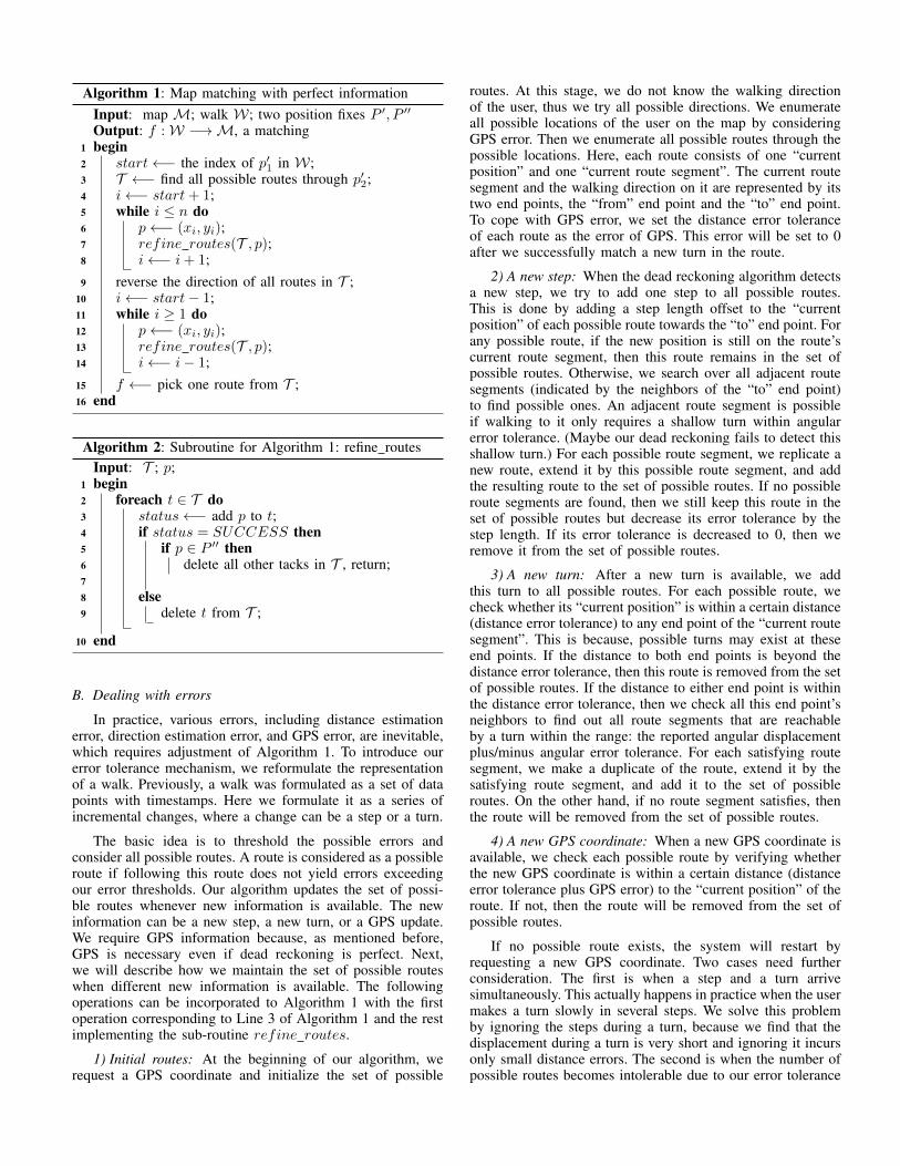
Algorithm 1: Map matching with perfect informationInput: map M; walk W; two position fixes P ′, P ′′Output: f :W −→M, a matchingbegin1
start←− the index of p′1 in W;2T ←− find all possible routes through p′2;3i←− start+ 1;4while i ≤ n do5
p←− (xi, yi);6refine routes(T , p);7i←− i+ 1;8
reverse the direction of all routes in T ;9i←− start− 1;10while i ≥ 1 do11
p←− (xi, yi);12refine routes(T , p);13i←− i− 1;14
f ←− pick one route from T ;15end16
Algorithm 2: Subroutine for Algorithm 1: refine routesInput: T ; p;begin1
foreach t ∈ T do2status←− add p to t;3if status = SUCCESS then4
if p ∈ P ′′ then5delete all other tacks in T , return;6
7else8
delete t from T ;9
end10
B. Dealing with errors
In practice, various errors, including distance estimationerror, direction estimation error, and GPS error, are inevitable,which requires adjustment of Algorithm 1. To introduce ourerror tolerance mechanism, we reformulate the representationof a walk. Previously, a walk was formulated as a set of datapoints with timestamps. Here we formulate it as a series ofincremental changes, where a change can be a step or a turn.
The basic idea is to threshold the possible errors andconsider all possible routes. A route is considered as a possibleroute if following this route does not yield errors exceedingour error thresholds. Our algorithm updates the set of possi-ble routes whenever new information is available. The newinformation can be a new step, a new turn, or a GPS update.We require GPS information because, as mentioned before,GPS is necessary even if dead reckoning is perfect. Next,we will describe how we maintain the set of possible routeswhen different new information is available. The followingoperations can be incorporated to Algorithm 1 with the firstoperation corresponding to Line 3 of Algorithm 1 and the restimplementing the sub-routine refine routes.
1) Initial routes: At the beginning of our algorithm, werequest a GPS coordinate and initialize the set of possible
routes. At this stage, we do not know the walking directionof the user, thus we try all possible directions. We enumerateall possible locations of the user on the map by consideringGPS error. Then we enumerate all possible routes through thepossible locations. Here, each route consists of one “currentposition” and one “current route segment”. The current routesegment and the walking direction on it are represented by itstwo end points, the “from” end point and the “to” end point.To cope with GPS error, we set the distance error toleranceof each route as the error of GPS. This error will be set to 0after we successfully match a new turn in the route.
2) A new step: When the dead reckoning algorithm detectsa new step, we try to add one step to all possible routes.This is done by adding a step length offset to the “currentposition” of each possible route towards the “to” end point. Forany possible route, if the new position is still on the route’scurrent route segment, then this route remains in the set ofpossible routes. Otherwise, we search over all adjacent routesegments (indicated by the neighbors of the “to” end point)to find possible ones. An adjacent route segment is possibleif walking to it only requires a shallow turn within angularerror tolerance. (Maybe our dead reckoning fails to detect thisshallow turn.) For each possible route segment, we replicate anew route, extend it by this possible route segment, and addthe resulting route to the set of possible routes. If no possibleroute segments are found, then we still keep this route in theset of possible routes but decrease its error tolerance by thestep length. If its error tolerance is decreased to 0, then weremove it from the set of possible routes.
3) A new turn: After a new turn is available, we addthis turn to all possible routes. For each possible route, wecheck whether its “current position” is within a certain distance(distance error tolerance) to any end point of the “current routesegment”. This is because, possible turns may exist at theseend points. If the distance to both end points is beyond thedistance error tolerance, then this route is removed from the setof possible routes. If the distance to either end point is withinthe distance error tolerance, then we check all this end point’sneighbors to find out all route segments that are reachableby a turn within the range: the reported angular displacementplus/minus angular error tolerance. For each satisfying routesegment, we make a duplicate of the route, extend it by thesatisfying route segment, and add it to the set of possibleroutes. On the other hand, if no route segment satisfies, thenthe route will be removed from the set of possible routes.
4) A new GPS coordinate: When a new GPS coordinate isavailable, we check each possible route by verifying whetherthe new GPS coordinate is within a certain distance (distanceerror tolerance plus GPS error) to the “current position” of theroute. If not, then the route will be removed from the set ofpossible routes.
If no possible route exists, the system will restart byrequesting a new GPS coordinate. Two cases need furtherconsideration. The first is when a step and a turn arrivesimultaneously. This actually happens in practice when the usermakes a turn slowly in several steps. We solve this problemby ignoring the steps during a turn, because we find that thedisplacement during a turn is very short and ignoring it incursonly small distance errors. The second is when the number ofpossible routes becomes intolerable due to our error tolerance
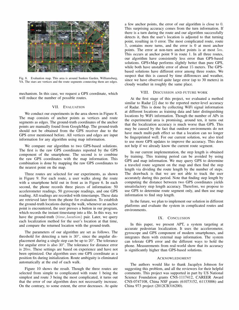
Fig. 8. Evaluation map. This area is around Sunken Garden, Williamsburg,VA. The stars are vertices and the route segments connecting them are edges.
mechanism. In this case, we request a GPS coordinate, whichwill reduce the number of possible routes.
VII. EVALUATION
We conduct our experiments in the area shown in Figure 8.The map consists of anchor points as vertices and routesegments as edges. The ground-truth coordinates of the anchorpoints are manually found from GoogleMap. The ground-truthshould not be obtained from the GPS receiver due to theGPS error mentioned before. All vertices and edges are inputinformation for any algorithm using map information.
We compare our algorithm to two GPS-based solutions.The first is the raw GPS coordinates reported by the GPScomponent of the smartphone. The second is to combinethe raw GPS coordinates with the map information. Thiscombination is done by mapping the raw GPS coordinates tothe nearest point on the map.
Three routes are selected for our experiments, as shownin Figure 9. For each route, a user walks along the routewith a smartphone held out in front as in Figure 6. In eachsecond, the phone records three pieces of information: 50accelerometer readings, 50 gyroscope readings, and one GPSreading. All readings are recorded with timestamps. These dataare retrieved later from the phone for evaluation. To establishthe ground-truth locations during the walk, whenever an anchorpoint is encountered, the user presses a button in our program,which records the instant timestamp into a file. In this way, wehave the ground-truth (time, location) pair. Later, we queryeach localization method for the user’s location at that time,and compare the returned location with the ground-truth.
The parameters of our algorithm are set as follows. Thethreshold for detecting a turn is 30◦, since the angular dis-placement during a single step can be up to 20◦. The tolerancefor angular error is also 30◦. The tolerance for distance erroris 20m. These settings are based on experience and have notbeen optimized. Our algorithm uses one GPS coordinate as aposition fix during initialization. Route ambiguity is eliminatedautomatically at the end of each walk.
Figure 10 shows the result. Though the three routes areselected from simple to complicated with route 1 being thesimplest and route 3 being the most complicated, it turns outthat the error of our algorithm does not necessarily increase.On the contrary, to some extent, the error decreases. At quite
a few anchor points, the error of our algorithm is close to 0.This surprising accuracy comes from the turn information. Ifthere is a turn during the route and our algorithm successfullydetects it, then the user’s location is adjusted to that turningpoint, resulting in 0 error. The most complicated route, route3, contains more turns, and the error is 0 at most anchorpoints. The error at non-turn anchor points is at most 5m.This occurs at anchor point 9 in route 1. In all three routes,our algorithm have consistently less error than GPS-basedsolutions. GPS+Map performs slightly better than pure GPS,while both have unstable error of about 15 meters. The GPS-based solutions have different error among three routes. Wesuspect that this is caused by time differences and weather,since we have observed quite large error (up to 30 meters) incloudy weather in roughly the same place.
VIII. DISCUSSION AND FUTURE WORK
At the first stage of this project, we evaluated a methodsimilar to Radar [2] due to the reported meter-level accuracyof Radar. This is done by collecting WiFi signal informationat different locations as training data and later distinguishinglocations by WiFi information. Though the number of APs inthe experimental area is promising, around ten, it turns outthat the localization accuracy is much worse than GPS. Thismay be caused by the fact that outdoor environments do nothave much multi-path effect so that a location can no longerbe fingerprinted well. For our current solution, we also triedto use more GPS updates to improve the accuracy. This doesnot help if we already know the current route segment.
In our current implementation, the step length is obtainedby training. This training period can be avoided by usingGPS and map information. We may query GPS to determinea traveled route segment on the map and then find the steplength via dividing the route length by the number of steps.The drawback is that we are not able to track the useraccurately during this period. Note that finding step length bycomputing the distance between two GPS coordinates yieldsunsatisfactory step length accuracy. Therefore, we propose touse GPS to determine route segment only, and then use mapinformation to find step length.
In the future, we plan to implement our solution in differentplatforms and evaluate the system in complicated routes andenvironments.
IX. CONCLUSION
In this paper, we present APT, a system targeting ataccurate pedestrian localization. It uses the accelerometer,gyroscope and GPS component of modern smartphones, andintegrates them with external map information. The systemcan tolerate GPS error and the different ways to hold thephone. Measurements from real-world show that its accuracyis significantly higher than GPS-based solutions.
ACKNOWLEDGMENT
The authors would like to thank Jacqulyn Johnson forsuggesting this problem, and all the reviewers for their helpfulcomments. This project was supported in part by US NationalScience Foundation grants CNS-1117412, CAREER AwardCNS-0747108, China NSF grants (61073152, 61133006) andChina 973 project (2012CB316200).

(a) Route 1 (b) Route 2 (c) Route 3
Fig. 9. Ground-truth routes.
1 2 3 4 5 6 7 8 9 10 110
5
10
15
anchor point
erro
r (m
)
APTGPSGPS+Map
(a) Route 1
1 2 3 4 5 6 7 8 9 10 11 12 13 140
2
4
6
8
10
anchor point
erro
r (m
)
APTGPSGPS+Map
(b) Route 2
1 2 3 4 5 6 7 8 9 10 11 12 13 14 15 160
2
4
6
8
10
12
anchor point
erro
r (m
)
APTGPSGPS+Map
(c) Route 3
Fig. 10. Localization errors at anchor points in the route.
REFERENCES
[1] F. B. Abdesslem, A. Phillips, and T. Henderson, “Less is more: energy-efficient mobile sensing with senseless,” in MobiHeld, 2009.
[2] P. Bahl and V. N. Padmanabhan, “Radar: An in-building rf-based userlocation and tracking system,” in INFOCOM, 2000.
[3] K. Chintalapudi, A. Padmanabha Iyer, and V. N. Padmanabhan, “Indoorlocalization without the pain,” in MobiCom, 2010.
[4] Y. Jin, M. Motani, W.-S. Soh, and J. Zhang, “Sparsetrack: Enhancingindoor pedestrian tracking with sparse infrastructure support,” in INFO-COM, 2010.
[5] B. Zhang, X. Cheng, N. Zhang, Y. Cui, Y. Li, and Q. Liang, “Sparse tar-get counting and localization in sensor networks based on compressivesensing,” in INFOCOM, 2011.
[6] M. Ding and X. Cheng, “Fault tolerant target tracking in sensornetworks,” in MobiHoc, 2009.
[7] X. Zhu, X. Wu, and G. Chen, “Refining hop-count for localisation inwireless sensor networks,” International Journal of Sensor Networks,vol. 12, no. 4, 2012.
[8] X. Zhu and G. Chen, “Spatial ordering derivation for one-dimensionalwireless sensor networks,” in ISPA, 2011.
[9] S. Gaonkar, J. Li, R. R. Choudhury, L. Cox, and A. Schmidt, “Micro-blog: sharing and querying content through mobile phones and socialparticipation,” in MobiSys, 2008.
[10] J. Froehlich, M. Y. Chen, S. Consolvo, B. Harrison, and J. A. Landay,“Myexperience: a system for in situ tracing and capturing of userfeedback on mobile phones,” in MobiSys, 2007.
[11] Foursquare. [Online]. Available: http://www.foursquare.com[12] K. Lin, A. Kansal, D. Lymberopoulos, and F. Zhao, “Energy-accuracy
trade-off for continuous mobile device location,” in MobiSys, 2010.[13] J. Paek, K.-H. Kim, J. P. Singh, and R. Govindan, “Energy-efficient po-
sitioning for smartphones using cell-id sequence matching,” in MobiSys,2011.
[14] M. B. Kjaergaard, J. Langdal, T. Godsk, and T. Toftkjaer, “Entracked:
energy-efficient robust position tracking for mobile devices,” in Mo-biSys, 2009.
[15] J. Paek, J. Kim, and R. Govindan, “Energy-efficient rate-adaptive gps-based positioning for smartphones,” in MobiSys, 2010.
[16] M. B. Kjaergaard, S. Bhattacharya, H. Blunck, and P. Nurmi, “Energy-efficient trajectory tracking for mobile devices,” in MobiSys, 2011.
[17] Z. Zhuang, K.-H. Kim, and J. P. Singh, “Improving energy efficiencyof location sensing on smartphones,” in MobiSys, 2010.
[18] H. S. Ramos, T. Zhang, J. Liu, N. B. Priyantha, and A. Kansal, “Leap:a low energy assisted gps for trajectory-based services,” in UbiComp,2011.
[19] B. Zhang, J. Teng, J. Zhu, X. Li, D. Xuan, and Y. F. Zheng, “Ev-loc:integrating electronic and visual signals for accurate localization,” inMobiHoc, 2012.
[20] J. Teng, B. Zhang, X. Li, X. Bai, and D. Xuan, “E-shadow: Lubricatingsocial interaction using mobile phones,” in ICDCS, 2011.
[21] S. Guha, K. Plarre, D. Lissner, S. Mitra, B. Krishna, P. Dutta, andS. Kumar, “Autowitness: locating and tracking stolen property whiletolerating gps and radio outages,” in SenSys, 2010.
[22] S. Rallapalli, L. Qiu, Y. Zhang, and Y.-C. Chen, “Exploiting temporalstability and low-rank structure for localization in mobile networks,” inMobiCom, 2010.
[23] H.-J. Jang, J. Kim, and D.-H. Hwang, “Robust step detection methodfor pedestrian navigation systems,” Electronics Letters, 2007.
[24] X. Zhu, F. Xu, E. Novak, C. C. Tan, Q. Li, and G. Chen, “Extractingsecret key from wireless link dynamics in vehicular environments,” inINFOCOM, 2013.
[25] P. Mohan, V. N. Padmanabhan, and R. Ramjee, “Nericell: using mobilesmartphones for rich monitoring of road and traffic conditions,” inSenSys, 2008.
[26] C. White, D. Bernstein, and A. Kornhauser, “Some map matchingalgorithms for personal navigation assistants,” Transportation ResearchPart C: Emerging Technologies, vol. 8, no. 1-6, pp. 91–108, Dec. 2000.