
Mike Middleton, CPA Deputy Finance Director, City and Borough of Sitka [email protected].
H332360, Rev. 0
© Hatch 2011/03
Project Report
April 4, 2011
City and Borough of Sitka
Blue Lake Expansion Project
General Construction & Underground Excavation Contracts Information Package

H332360, Rev. 0, Page i
© Hatch 2011/03
Table of Contents
1. Introduction ............................................................................................................................................ 1
2. Project Description & Scope of Work ..................................................................................................... 2
2.1 Project Description ........................................................................................................................ 2 2.2 Geologic Site Conditions................................................................................................................ 4 2.3 General Construction Contract ....................................................................................................... 8
2.3.1 General ................................................................................................................................ 8 2.3.2 Expanded Reservoir Area ...................................................................................................... 9 2.3.3 Intake Structure .................................................................................................................. 10 2.3.4 Dam Structure .................................................................................................................... 11 2.3.5 Fish Valve Unit Arrangement and Operation ...................................................................... 11 2.3.6 Tunnel Modification ........................................................................................................... 12 2.3.7 City Municipal Water System ............................................................................................. 12 2.3.8 Powerhouse and Penstock .................................................................................................. 12
2.4 Power for Construction ................................................................................................................ 14 2.5 Water for Construction ................................................................................................................. 14 2.6 Sewer for Construction ................................................................................................................. 14 2.7 City Supplied Equipment .............................................................................................................. 14 2.8 Underground Excavation Contract (No. 8) .................................................................................... 15
2.8.1 General .............................................................................................................................. 15 2.8.2 Intake Tunnel ..................................................................................................................... 16 2.8.3 Surge Chamber ................................................................................................................... 16
2.9 Work Activities to be Self-Performed by City ................................................................................ 17
3. Construction Constraints and Preliminary Schedule ............................................................................. 17
3.1 General ........................................................................................................................................ 17 3.2 General Development Schedule ................................................................................................... 17 3.3 Reservoir Operating Constraints ................................................................................................... 18 3.4 Climate ........................................................................................................................................ 19 3.5 Hydrology Records ...................................................................................................................... 20 3.6 Historical Spillway Flows and Plunge Pool Water Levels .............................................................. 20 3.7 Constraints on Streamflow in Sawmill Creek ................................................................................ 20 3.8 Contractor Staging Areas .............................................................................................................. 20
3.8.1 Sawmill Cove Industrial Park .............................................................................................. 20 3.8.2 Dam Site Staging Area ........................................................................................................ 21
3.9 Access Roads for Contractor Use .................................................................................................. 22 3.9.1 Dam Site Access Road Use ................................................................................................. 22 3.9.2 Powerhouse Access Road ................................................................................................... 23
3.10 City-Furnished Equipment Deliveries ........................................................................................... 23 3.11 Concrete Aggregate Sources ......................................................................................................... 24 3.12 Dam Construction Considerations ................................................................................................ 24
3.12.1 Possible Crane Tower Location .......................................................................................... 24 3.12.2 Concrete Placement Sequence ........................................................................................... 26 3.12.3 Schedule Constraints for Dam Grouting ............................................................................. 27
3.13 Generation Outage Duration ........................................................................................................ 27
4. Commercial Terms and Conditions ....................................................................................................... 29

City and Borough of Sitka – Blue Lake Expansion Project
General Construction & Underground Construction Contracts Information Package
H332360, Rev. 0, Page ii
© Hatch 2011/03
4.1 General ........................................................................................................................................ 29 4.2 Performance and Payment Bonds ................................................................................................. 29
5. Opportunities for Contractor Visits to Blue Lake Site ........................................................................... 29
List of Figures
Figure 1.1 – Site Map Figure 2.1 – Location of Existing Blue Lake Project Figure 2.2 - Blue Lake Project Power Conduit Schematic Figure 2.3 – Geotechnical Findings Report – Regional Geology Figure 2.4 – Blue Lake Reservoir Outline for Reservoir Clearing Figure 2.5 – Proposed Intake Tunnel Profile Figure 2.6 - Blue Lake Dam Raise – Elevation and Cross Section Figure 2.7 – Proposed Powerhouse and Penstock Site Plan Figure 2.8 – Proposed Blue Lake Powerhouse Addition Figure 2.9 – Location of Dam Site Power Distribution Line Figure 2.10 – Profile of Proposed Surge Chamber Figure 3.1 – Construction Schedule Figure 3.2 - Reservoir Operation during Construction and Initial Operation Figure 3.3 – SCIP Laydown Area Available for Construction Contractor Figure 3.4 - Dam Site Staging Area (to be developed by the GCC) Figure 3.5 – Blue Lake Road Modifications (to be developed by the GCC) Figure 3.6 – Possible Crane Tower Locations for Dam Construction Figure 3.7 – Possible Crane Tower Locations – Section and Elevation Views Figure 3.8 – Arch Dam Construction Block Configuration
List of Photographs
Photo 1 - photo of arch dam from downstream Photo 7 - left abutment above arch dam Photo 8 - Left abutment joints Photo 9 - Closely spaced discontinuity zone, left abutment Photo 11 - Left abutment of existing dam Photo 14 - View of top of left abutment Photo 19 - View of right abutment Photo 20 - View of intake area Photo 21 - View of downstream portal of upper tunnel Photo 22 - View of downstream portal of lower tunnel Photo 26 - View of Surge chamber Photo 27 - View of the downstream portal of the lower tunnel Photo 28 - View of the timber crib wall Photo 31 - View of the powerhouse site (may not want to include this since it does not show a whole lot).

City and Borough of Sitka – Blue Lake Expansion Project
General Construction & Underground Construction Contracts Information Package
H332360, Rev. 0, Page iii
© Hatch 2011/03
List of Drawings
Contract No. 8: Underground Excavation Number Title 109-05-001 General Project Location Map 109-05-002 Powerhouse Area Contractors Work Areas 109-05-006 Dam and Intake Site Plan 109-05-020 Intake Tunnel Profile 109-30-041 Surge Shaft Adit Tunnel Plans and Profile Contract No. 9: General Construction Number Title 109-25-011 Intake Structure General Arrangement Base Slab Plan 109-25-012 Intake Structure General Arrangement Roof Plan 109-25-021 Intake Structure Trashrack General Arrangement 109-26-002 Gate Shaft Gate Chamber Concrete Outline 109-26-011 Gate House General Arrangement Plans and Sections 109-31-011 Penstock Installation Plan 109-31-013 Penstock Installation Plan and Sections 109-45-001 Powerhouse Area Site Plan 109-45-013 Powerhouse General Arrangement Plan El 39.00 and Section 109-45-014 Powerhouse General Arrangement Plan El 27.00 109-45-015 Powerhouse General Arrangement Plan El 13.00 109-45-017 Powerhouse General Arrangement Transverse Section 109-45-019 Powerhouse General Arrangement Longitudinal Section 109-45-101 Powerhouse One Line Diagram 69kV – 12.47kV 109-45-102 Powerhouse 480 V One Line Diagram Station Service Bus ST1 and ST2 109-46-001 FVU Powerhouse Site Plan 109-46-002 FVU Powerhouse General Arrangement Plan
City and Borough of Sitka – Blue Lake Expansion Project
General Construction & Underground Construction Contracts Information Package
H332360, Rev. 0, Page 1
© Hatch 2011/02
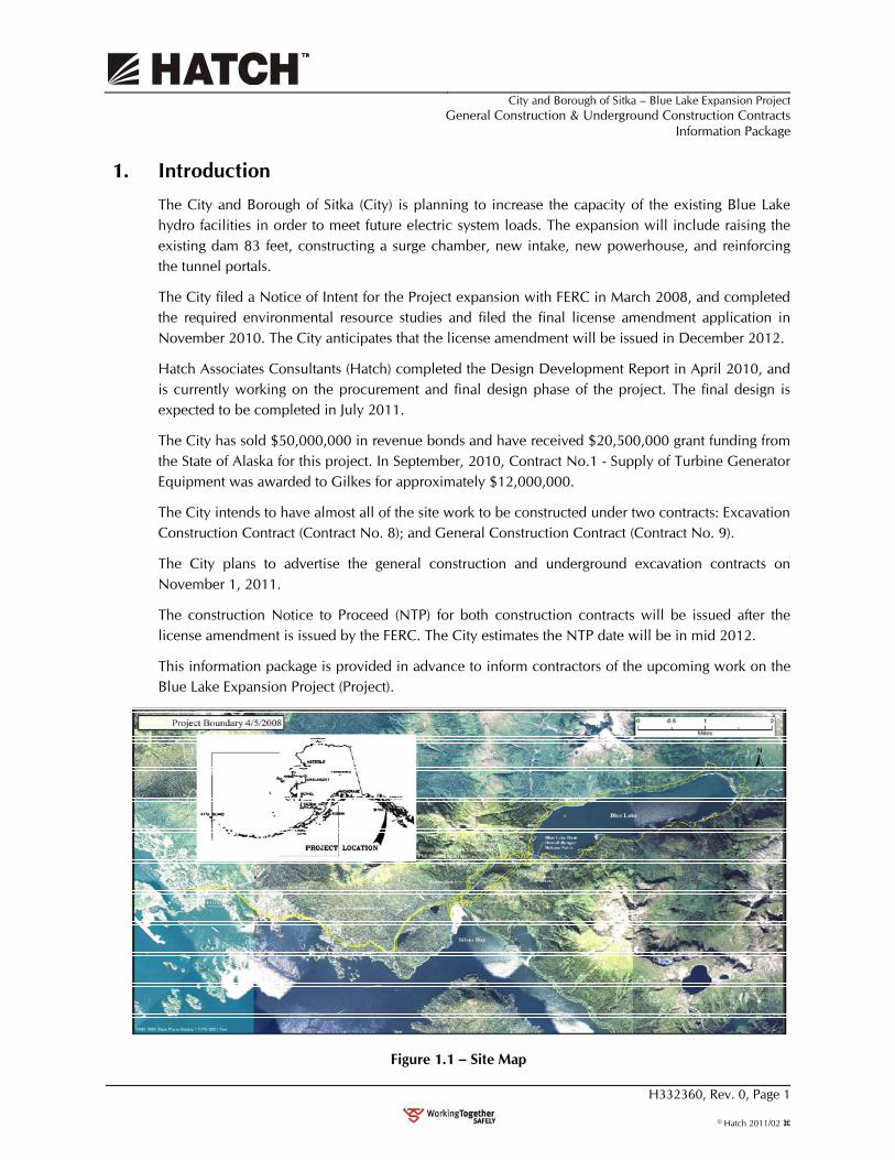
1. Introduction The City and Borough of Sitka (City) is planning to increase the capacity of the existing Blue Lake hydro facilities in order to meet future electric system loads. The expansion will include raising the existing dam 83 feet, constructing a surge chamber, new intake, new powerhouse, and reinforcing the tunnel portals.
The City filed a Notice of Intent for the Project expansion with FERC in March 2008, and completed the required environmental resource studies and filed the final license amendment application in November 2010. The City anticipates that the license amendment will be issued in December 2012.
Hatch Associates Consultants (Hatch) completed the Design Development Report in April 2010, and is currently working on the procurement and final design phase of the project. The final design is expected to be completed in July 2011.
The City has sold $50,000,000 in revenue bonds and have received $20,500,000 grant funding from the State of Alaska for this project. In September, 2010, Contract No.1 - Supply of Turbine Generator Equipment was awarded to Gilkes for approximately $12,000,000.
The City intends to have almost all of the site work to be constructed under two contracts: Excavation Construction Contract (Contract No. 8); and General Construction Contract (Contract No. 9).
The City plans to advertise the general construction and underground excavation contracts on November 1, 2011.
The construction Notice to Proceed (NTP) for both construction contracts will be issued after the license amendment is issued by the FERC. The City estimates the NTP date will be in mid 2012.
This information package is provided in advance to inform contractors of the upcoming work on the Blue Lake Expansion Project (Project).
Figure 1.1 – Site Map
City and Borough of Sitka – Blue Lake Expansion Project
General Construction & Underground Excavation Contracts Information Package
H332360, Rev. 0, Page 2
© Hatch 2011/03
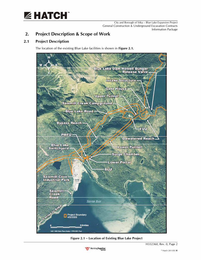
2. Project Description & Scope of Work 2.1 Project Description
The location of the existing Blue Lake facilities is shown in Figure 2.1.
Figure 2.1 – Location of Existing Blue Lake Project

City and Borough of Sitka – Blue Lake Expansion Project
General Construction & Underground Excavation Contracts Information Package
H332360, Rev. 0, Page 3
© Hatch 2011/03
The major features of the Project are comprised of the following:
• increasing the height of the Blue Lake Dam by 83 ft, to increase the maximum gross head of the plant from 329 ft to 413 ft;
• modification of the waterways from the dam to the powerhouse, including the addition of a new power intake, intake tunnel, gate shaft and surge chamber;
• decommissioning of the existing 6 MW powerhouse and construction of a new powerhouse with three 5.3 MW (nominal capacity) generating units (BLU);
• modification to the existing switchyard;
• relocation of the existing Sitka electric system control center to the new Blue Lake powerhouse;
• replacement of the Fish Valve Unit (FVU) with a new unit designed for higher operating head; and
• decommissioning of the Pulp Mill Feeder Unit (PMFU).
The existing Blue Lake dam was constructed in the period 1959-1961, and retains the reservoir for the Blue Lake hydroelectric facility. The dam is a concrete arch structure approximately 145 ft high from the foundation to the crest El 345.0, with a crest length of 256 ft and a crest width of 8 ft. A six-foot-high parapet wall extends above the dam crest to El 351.
An existing 7,110 ft. long power conduit consists of an Upper Tunnel, an Upper Penstock, a Lower Tunnel and a Lower Penstock. The Upper Tunnel comprises an unlined, 11.5 ft. diameter modified horseshoe cross section extending 1,442 feet from the intake structure to the upper penstock (the North Portal) on the right side of Sawmill Creek (Figure 2.2). The Upper Penstock is an 84 in. diameter, 595-foot-long steel pipe, which crosses Sawmill Creek and is supported on concrete piers; it enters the Lower Tunnel at the South Portal on the stream’s left side. The 5,000 ft. long, 10.5 ft. diameter Lower Tunnel is mostly unlined and extends to the Lower Portal where the Lower Penstock continues to the existing powerhouse.
Primary access to the Project dam from Sawmill Creek Road is via the 2.18 mile-long USFS road No. 5755 (Blue Lake Road). Access to the FVU is via USFS road No. 5755 (the Sawmill Creek Campground access road) which branches from road No. 5755. Access to the BLU and the PMFU is via a short licensee-owned road connecting to Sawmill Creek Road at mile 5.5.

City and Borough of Sitka – Blue Lake Expansion Project
General Construction & Underground Excavation Contracts Information Package
H332360, Rev. 0, Page 4
© Hatch 2011/03
Figure 2.2 - Blue Lake Project Power Conduit Schematic – Existing Facilities
2.2 Geologic Site Conditions
Geotechnical investigations were carried out, during May through October, 2009, to obtain design parameters for carrying out design development and undertaking final design for a proposed raise of the Blue Lake Dam.
These investigations included geological mapping at the dam, intake, South Portal, surge chamber and powerhouse sites. The work also included drilling a total of 15 boreholes:

City and Borough of Sitka – Blue Lake Expansion Project
General Construction & Underground Excavation Contracts Information Package
H332360, Rev. 0, Page 5
© Hatch 2011/03
• Seven holes at the dam site;
• Three along the intake and intake tunnel;
• One above the South portal;
• One at the surge chamber;
• One at the powerhouse site; and
• Two along a suspected buried valley under the Blue Lake access road at the right abutment.
Of the seven holes at the dam, four were drilled at the left abutment, two were drilled at the right abutment and one was drilled in the plunge pool. Seismic refraction surveys were undertaken over a potential seepage path located to the west of the right abutment along the existing Blue Lake access road. The purpose of the seismic refraction survey was to determine the depth to bedrock along the axis buried valley.
Blue Lake occupies the west end of a broad glacial U-shaped valley. The lower end of the lake is bounded by bedrock cliffs up to 300 ft in height. The cliffs are steepest on the west and north shores of the lake and less steep on the south shore. The valley slopes are mantled with colluvium and talus deposits of variable thickness with bedrock outcrops exposed on the steeper slopes. The results of the USBR (1954) investigation indicate that there are some remnants of glacial till in the areas, in particular in the saddle in the right abutment of the dam. In addition, glacial errata, primarily of igneous origin have been deposited in the in the stream channel of Sawmill Creek and on the valley floor.
As shown on Figure 2.3 (at end of this Section), Blue Lake Dam is located where Sawmill Creek enters a steep canyon that extends down to the Fish Valve Unit (FVU) powerhouse site where there is a Forest Service Campground. At this location, where the canyon ends, the valley widens considerably for an approximately 0.5 miles before entering a second narrow section, which discharges into Sawmill Cove near the Blue Lake Powerhouse site.
Figure 2.3 also shows the regional geology. The two main bedrock units underlying the project area belong to the Kelp Bay Group (Haeussler et. al. 2004). The first unit occurs (north of STA 50+00 on the lower tunnel alignment and south of approximately STA 22+00 on the Lower Tunnel alignment. This unit is described by the U.S. Geological Survey (USGS) (Loney et al. 1964) as a Triassic to Jurassic-aged “greenstone, graywacke, greenschist, metachert, and phyllite”. The unit located along most of the Lower Tunnel alignment between STA 22+00 and 50+00 is a Permian- to Triassic aged greenstone (metamorphosed volcanic rock, likely of andesitic composition).
The Project components that will be affected by the raised lake level include the new intake tunnel, the arch dam and plunge pool, the South River Portal, the North River Portal, the Lower Portal, the proposed new surge chamber, and a new penstock and powerhouse. All of these areas are underlain by the graywacke.


City and Borough of Sitka – Blue Lake Expansion Project
General Construction & Underground Excavation Contracts Information Package
H332360, Rev. 0, Page 6
© Hatch 2011/03
Based on the results of geological mapping three major sets of discontinuities occur within the project area with the following orientations (Dip/Direction):
• Set 1 – 87°/300°
• Set 2 – 72°/214°
• Set 3 – 33°/320°
Joint Set 1 is parallel to the channel walls at the arch dam and forms the steep exposures in the cliff above the powerhouse portal. Set 2 is parallel to bedding. Joint Set 3 is less well defined than Sets 1 and 2, except at the arch dam. In general, the joints have planar shape, have a smooth to rough surface, and are slightly weathered, and are generally tight. The joint spacing for Sets 1 and 2 is 0.7 to 2 ft and the spacing for Set 3 is 1 to 6 ft. The persistence of jointing in the project area typically ranges from 3 to over 30 ft; however, individual joints in the abutments of the arch dam and other steep exposures were observed to have persistences in excess of 100 ft. The average RQD from core from the seven boreholes drilled at the dam is 95%.
1. Dam Site
For the most part, the bedrock at the arch dam site was found to be relatively impermeable and most of the intervals tested have hydraulic conductivities less than 3.6 x 10⁻⁶ ft/s. However, there were a few zones, approximately 10 – 20 ft in length, with higher takes in excess of 1.0 x 10⁻⁵ ft/s. On the left abutment, these include a 21-ft long zone, are intersected by both DH09-01 and DH09-02. During drilling operations, a connection was noted between these two holes. DH09-04 also intersected a higher permeability zone with a hydraulic conductivity of 4.0 x 10⁻⁶ ft/s to 6.0 x 10⁻⁶ ft/s. Borehole DH09-04 was drilled through the concrete into bedrock and the concrete-bedrock contact in this hole is bonded.
On the right abutment, DH09-07 and DH09-11 each intersected 10 ft zones with hydraulic conductivities of 4.0 x 10⁻⁶ ft/s to 9.0 x 10⁻⁶ ft/s, respectively.
The dam is located of the top of an older stream channel that was excavated to El 140 and filled with a concrete plug. It is suspected that the channel was originally cut, along an area of closely spaced jointing, by glaciation and infilled with glacial till, which was washed out as the glacier retreated, except possibly in a deep section, under the dam, where a small till deposit was wedged in place and could not be eroded. The channel was then subsequently infilled with talus and alluvium. This channel extends downstream into the plunge pool and is formed by Joint Set 1. DH09-08 was drilled through 21 ft of boulders and gravel and encountered a high permeability zone (calculated to be 2.1 x 10⁻³ ft/s) in the top 10 ft of the bedrock. If this fractured rock is present under the dam, it would likely have been sealed by the grouting program implemented during dam construction. The RQD of the bedrock obtained from this zone was indicative of poor to fair quality rock (30% to 62%). The remainder of the borehole passed through excellent quality rock (RQD of 96% to 100%).
2. Penstock and Powerhouse Site
The bedrock of the proposed surge chamber and the powerhouse sites is the graywacke unit. Based on the results of the tunnel inspection and the results of the drilling a borehole at the surge chamber, RMR values between 60 and 70 would be anticipated for most of the surge chamber, the exception
City and Borough of Sitka – Blue Lake Expansion Project
General Construction & Underground Excavation Contracts Information Package
H332360, Rev. 0, Page 7
© Hatch 2011/03
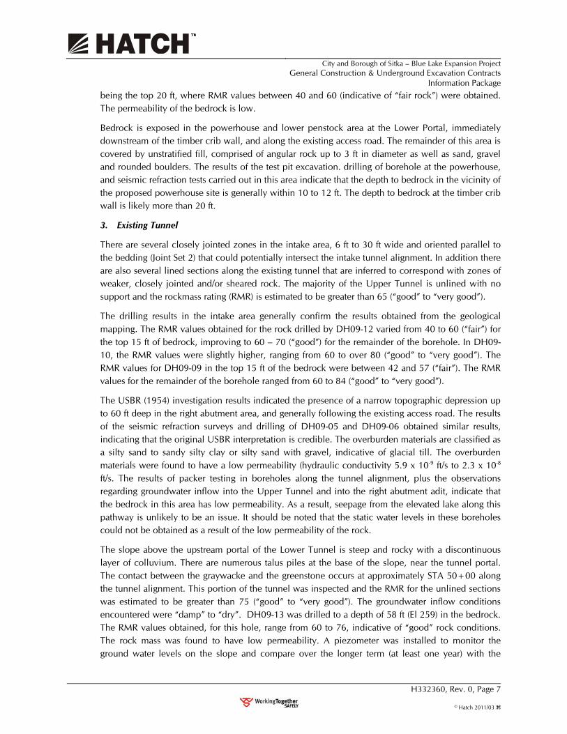
being the top 20 ft, where RMR values between 40 and 60 (indicative of “fair rock”) were obtained. The permeability of the bedrock is low.
Bedrock is exposed in the powerhouse and lower penstock area at the Lower Portal, immediately downstream of the timber crib wall, and along the existing access road. The remainder of this area is covered by unstratified fill, comprised of angular rock up to 3 ft in diameter as well as sand, gravel and rounded boulders. The results of the test pit excavation. drilling of borehole at the powerhouse, and seismic refraction tests carried out in this area indicate that the depth to bedrock in the vicinity of the proposed powerhouse site is generally within 10 to 12 ft. The depth to bedrock at the timber crib wall is likely more than 20 ft.
3. Existing Tunnel
There are several closely jointed zones in the intake area, 6 ft to 30 ft wide and oriented parallel to the bedding (Joint Set 2) that could potentially intersect the intake tunnel alignment. In addition there are also several lined sections along the existing tunnel that are inferred to correspond with zones of weaker, closely jointed and/or sheared rock. The majority of the Upper Tunnel is unlined with no support and the rockmass rating (RMR) is estimated to be greater than 65 (“good” to “very good”).
The drilling results in the intake area generally confirm the results obtained from the geological mapping. The RMR values obtained for the rock drilled by DH09-12 varied from 40 to 60 (“fair”) for the top 15 ft of bedrock, improving to 60 – 70 (“good”) for the remainder of the borehole. In DH09-10, the RMR values were slightly higher, ranging from 60 to over 80 (“good” to “very good”). The RMR values for DH09-09 in the top 15 ft of the bedrock were between 42 and 57 (“fair”). The RMR values for the remainder of the borehole ranged from 60 to 84 (“good” to “very good”).
The USBR (1954) investigation results indicated the presence of a narrow topographic depression up to 60 ft deep in the right abutment area, and generally following the existing access road. The results of the seismic refraction surveys and drilling of DH09-05 and DH09-06 obtained similar results, indicating that the original USBR interpretation is credible. The overburden materials are classified as a silty sand to sandy silty clay or silty sand with gravel, indicative of glacial till. The overburden materials were found to have a low permeability (hydraulic conductivity 5.9 x 10⁻⁹ ft/s to 2.3 x 10⁻⁸ ft/s. The results of packer testing in boreholes along the tunnel alignment, plus the observations regarding groundwater inflow into the Upper Tunnel and into the right abutment adit, indicate that the bedrock in this area has low permeability. As a result, seepage from the elevated lake along this pathway is unlikely to be an issue. It should be noted that the static water levels in these boreholes could not be obtained as a result of the low permeability of the rock.
The slope above the upstream portal of the Lower Tunnel is steep and rocky with a discontinuous layer of colluvium. There are numerous talus piles at the base of the slope, near the tunnel portal. The contact between the graywacke and the greenstone occurs at approximately STA 50+00 along the tunnel alignment. This portion of the tunnel was inspected and the RMR for the unlined sections was estimated to be greater than 75 (“good” to “very good”). The groundwater inflow conditions encountered were “damp” to “dry”. DH09-13 was drilled to a depth of 58 ft (El 259) in the bedrock. The RMR values obtained, for this hole, range from 60 to 76, indicative of “good” rock conditions. The rock mass was found to have low permeability. A piezometer was installed to monitor the ground water levels on the slope and compare over the longer term (at least one year) with the

City and Borough of Sitka – Blue Lake Expansion Project
General Construction & Underground Excavation Contracts Information Package
H332360, Rev. 0, Page 8
© Hatch 2011/03
changes in lake levels. The initial piezometer readings to October 31, 2009) indicated that the ground water levels were between El 292 and El 296.
2.3 General Construction Contract
2.3.1 General
In order of appearance, Project features are generally listed from the most upstream features at the dam site to the most downstream features at the powerhouse. The work under this contract includes the following:
1. Construction of staging area in the intake and dam area (Figure 3.4);
2. Re-grading of the Blue Lake road from Sawmill Creek Road to the dam site (Figure3.5);
3. Blue Lake dam work including raising the height of the dam by 83 ft (Figure 2.6);
4. Construction of a new tunnel intake structure, excluding portal excavation, but including supply and installation of trashrack frame and installation of intake bulkhead gate (Drawing 109-25-012);
5. Intake gate shaft work, including: a) concrete work in the intake tunnel at the gate shaft, b) construction of the gate house; c) concrete crane pad area for trashrack installation and removal; d) installation and testing of the fixed wheel gate guides, gate and hoist (Drawings 109-26-002 and 109-26-011);
6. Intake tunnel tie-in including excavation of the rock plug between new intake tunnel and existing upper tunnel and construction of a concrete plug in the existing tunnel just upstream of the tunnel tie-in to isolate the existing intake from the waterways;
7. Extending the steel tunnel liner at three different tunnel portals for a collective length of 206 feet;
8. Construction of metal rock traps in the lower and upper tunnels;
9. Excavating connecting shaft from the surge chamber adit tunnel to the existing Lower Tunnel (see Figure 2.10);
10. Placement of concrete plug to seal the surge chamber adit tunnel (see Figure 2.10);
11. Modification of fish valve unit (FVU) (see Drawings109-46-001 and 109-46-002) including:
a. Removal of existing turbine, generator and exciter;
b. Demolition of existing turbine and generator foundations as necessary;
c. Installation on new FVU turbine, generator and exciter;
d. Supply and installation of new powerhouse fans and louvers;
e. Modification of FVU bypass energy dissipater;
f. Concrete modifications to the downstream powerhouse wall;
g. Electrical interconnection between the new turbine and generator and the existing controls and transformer.
12. Excavation of penstock, powerhouse and afterbay area for the new powerhouse and penstock including penstock manifold;
13. Construction/excavation of access road from highway to the powerhouse (see Figure 2.7);
14. Demolition of the existing above ground penstock and guard valve at the lower portal (see Figure 2.7);

City and Borough of Sitka – Blue Lake Expansion Project
General Construction & Underground Excavation Contracts Information Package
H332360, Rev. 0, Page 9
© Hatch 2011/03
15. Installation of new penstock and manifold including flanged connection to existing flange at the lower portal, reconnection of line to the City water treatment plant, penstock 24 inch drain and drain energy dissipation items;
16. Construction of new powerhouse (see Drawings 109-45-001 through 109-45-019) including:
a. Civil structures;
b. Electrical services, cable tray, conduit and wiring;
c. Mechanical services, piping and instrumentation;
d. Erection of pre-engineered powerhouse superstructure;
e. Installation of turbine and generator equipment;
f. Installation of switchgear;
g. Installation of bridge crane;
h. Construct control room;
17. Construction of afterbay, including concrete slab near powerhouse, weir, stoplog supports, wood stoplogs, and weir bulkhead for raw water pumps;
18. Construction of raw water pump station in the afterbay area, including the structure, pumps, valves, controls, intake screens and piping interconnection to the industrial water supply piping and the municipal water supply piping; and
19. Testing and commissioning of all equipment installed by the contractor.
Approximate material and spoils balance indicating quantities of excavation, spoils, rock, and concrete required for all contracts in the Blue Lake Expansion Project:
Excavation Summary (CY) Total Overburden 19,000 Total surplus Rock 75,000 Total Crushed Rock 11,600 Concrete Summary (CY) Powerhouse and tunnels 4,000 Dam and thrust blocks 8,000
2.3.2 Expanded Reservoir Area
The expanded reservoir area after the dam is raised is shown in Figure 3.4. Reservoir clearing will be required. This will be done by a separate contractor between the existing normal maximum pool El 342 to the proposed normal maximum pool El 425, which is shown in Figure 2.4. Reservoir operation, as shown in Figure 3.2, presents the expected lake levels for intake/dam construction and removal of timber from the reservoir.

City and Borough of Sitka – Blue Lake Expansion Project
General Construction & Underground Excavation Contracts Information Package
H332360, Rev. 0, Page 10
© Hatch 2011/03
Figure 2.4 – Blue Lake Reservoir Outline for Reservoir Clearing
2.3.3 Intake Structure
The existing intake structure will be decommissioned during the generation outage. A new intake structure will be constructed by the Underground Excavation Contractor (UEC) and General Construction Contractor (GCC) (Figure 2.5). The UEC will excavate an access road from the dam site staging area to the intake portal, the tunnel, intake shaft and associated rock supports(Figure 3.4).
Figure 2.5 – Proposed Intake Tunnel Profile

City and Borough of Sitka – Blue Lake Expansion Project
General Construction & Underground Excavation Contracts Information Package
H332360, Rev. 0, Page 11
© Hatch 2011/03
2.3.4 Dam Structure
The mass concrete structure to be placed on top of the existing crest is a single arch shape with a constant thickness of 8-feet, which would extend vertically upwards to elevation 428 (Figure 2.6). The structure is divided into 7 blocks from right to left, each with a length of 45 feet, except for the abutment lifts, which would be less than 30 feet long. Each lift is planned to be 10-feet high. To provide adequate of forces from the arch dam to the rock abutment, a thrust block would be required at the left abutment. The thrust block and associated cut-off wall would be concrete gravity structures and include a drainage system to lower the water table to the level of the drain pipes.
Figure 2.6 - Blue Lake Dam Raise – Elevation and Cross Section
The reinforced spillway structure may have a buttress support design similar to the existing spillway design. While the ogee shape is defined by Hatch, the structural element is being reviewed to determine how to minimize the structure cost based on constructability and design considerations.
The grout curtain design would be located at the upstream edge of the proposed dam shell structure such that it can be taken off of the critical path and be constructed following placement of the arch dam rather than before it. On the left abutment, the alignment of the grout curtain does not follow beneath the thrust block or cut-off wall, but extends between these two structures normal to the ground contours.
2.3.5 Fish Valve Unit Arrangement and Operation
The Fish Valve Unit (FVU) is located on Sawmill Creek between the North and South river portals. The FVU provides an instream flow release to Sawmill Creek, which varies between 50 and 70 cfs. The City has non power producing alternate sources for the instream flow so the work on the FVU is

City and Borough of Sitka – Blue Lake Expansion Project
General Construction & Underground Excavation Contracts Information Package
H332360, Rev. 0, Page 12
© Hatch 2011/03
not in the critical path. The existing turbine generator at the FVU will be replaced with a 1.6MW turbine generator supplied under contract no. 1 (Drawings 109-46-001 and 109-46-002).
2.3.6 Tunnel Modification
Tunnel Modification during the generation outage will be performed by the GCC. The work has been limited to minimize the generation outage period. The principal modifications required during the generation outage are the tunnel liner extensions, the installation of metal rock traps and tunnel tie-ins. The tunnel tie-ins will consist of connecting the new intake tunnel with the upper tunnel and the surge chamber with the lower tunnel. Concrete plugs will be required at both locations. The generation outage work is expected to be completed during a 4 to 6 week period.
2.3.7 City Municipal Water System
The Blue Lake reservoir and penstock are the primary source of drinking water for the City. The reservoir and penstock will be utilized for drinking water before during and after construction except during the generation outage. The water quality must be monitored and protected at all times.
The municipal water treatment plant (WTP) is connected to the penstock at the lower portal. A 30” water transmission main runs from the WTP through the new power house site to town. It will be necessary for the GCC to reroute the 30” water transmission main around the new powerhouse and install the new penstock over this water main (Drawing 109-31-013). The power distribution feeder to the WTP will be supplied from the new powerhouse by the GCC.
2.3.8 Powerhouse and Penstock
Figures 2.7 and 2.8 present the location of the existing and proposed powerhouse structures, including the connecting penstock from the Lower Portal.
Figure 2.7 – Proposed Powerhouse and Penstock Site Plan
City and Borough of Sitka – Blue Lake Expansion Project
General Construction & Underground Excavation Contracts Information Package
H332360, Rev. 0, Page 13
© Hatch 2011/03
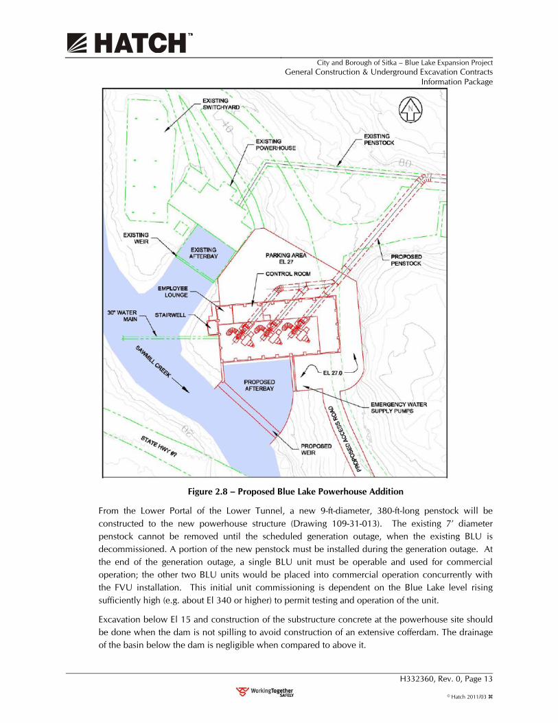
Figure 2.8 – Proposed Blue Lake Powerhouse Addition
From the Lower Portal of the Lower Tunnel, a new 9-ft-diameter, 380-ft-long penstock will be constructed to the new powerhouse structure (Drawing 109-31-013). The existing 7’ diameter penstock cannot be removed until the scheduled generation outage, when the existing BLU is decommissioned. A portion of the new penstock must be installed during the generation outage. At the end of the generation outage, a single BLU unit must be operable and used for commercial operation; the other two BLU units would be placed into commercial operation concurrently with the FVU installation. This initial unit commissioning is dependent on the Blue Lake level rising sufficiently high (e.g. about El 340 or higher) to permit testing and operation of the unit.
Excavation below El 15 and construction of the substructure concrete at the powerhouse site should be done when the dam is not spilling to avoid construction of an extensive cofferdam. The drainage of the basin below the dam is negligible when compared to above it.

City and Borough of Sitka – Blue Lake Expansion Project
General Construction & Underground Excavation Contracts Information Package
H332360, Rev. 0, Page 14
© Hatch 2011/03
2.4 Power for Construction
Electric power for construction will be provided at the City’s industrial rate of about 9 cents/kWh. 4160V power will be available at the powerhouse site from the distribution line located between the WTP and switchyard (Fig. 2.7). 12470V power will be provided at the FVU, the Sawmill Creek crossing portals and the dam/intake tunnel site as shown in Figure 2.9. 12470V and office power will be available at the SCIP.
Figure 2.9 – Location of Dam Site Power Distribution Line
2.5 Water for Construction
Non-potable water will be available at Powerhouse, FVU, and Lower portal sites, except during the generation outage. Water at the dam site will have to be pumped from the reservoir elevation. Potable water will be available at the Sawmill Creek Industrial Park (SCIP) and the BLU powerhouse site following installation of the potable water line installed by the GCC.
2.6 Sewer for Construction
No sanitary sewer is supplied to the construction site except the SCIP.
2.7 City Supplied Equipment
Equipment and structures supplied by others and to be installed by the GCC is comprised of the following:
1. BLU turbine and generator equipment including turbines, HPU’s, turbine inlet valves, generators, exciters and control panels with governors.
City and Borough of Sitka – Blue Lake Expansion Project
General Construction & Underground Excavation Contracts Information Package
H332360, Rev. 0, Page 15
© Hatch 2011/03
2. FVU turbine and generator equipment including turbine, gate positioner, generator, exciter and turbine inlet valve.
3. Bridge crane for BLU powerhouse.
4. Bulkhead gate, fixed wheel gate, fixed wheel gate guides and fixed wheel gate hoist.
5. Penstock including manifold, penstock, and tunnel liners.
6. Steel building (BLU powerhouse superstructure) including structural steel, anchors, wall panels, doors, window, louvers and dampers, crane runway, crane rails, end stops.
7. Powerhouse switchgear.
8. Switchyard 69kV main transformers.
A suppliers representative will be provided (at City’s discretion) for the equipment in Items 1, 2, 3, 4 (hoist only), 7 and 8.
2.8 Underground Excavation Contract (No. 8)
2.8.1 General
Presently, the City is envisioning separate construction contracts for the UEC and GCC work; although this could change based on consultation with potential contractors. It will be absolutely necessary that if separate contracts are issued that both contractors work cooperatively to schedule work and share access to the job sites.
All work performed during the generation outage must be scheduled and well coordinated to minimize the duration of the outage; therefore, the generation outage work will be performed by a single contractor. The tunnel tie in work is to be performed by the GCC. It is possible that the UEC could be retained as a subcontractor to the GCC in completing a portion of this work.
Work under UEC contract includes:
1. Limited excavation of staging area at dam/intake area, which would include excavation to design grade of finished gate shaft;
2. Excavation of access road to intake portal (Figure 3.4);
3. Intake Portal excavation and permanent rock supports, as required;
4. Intake tunnel excavation 10 ft wide by 12-ft high horseshoe shape to within 30 feet of connecting to existing tunnel, inclusive of rock supports, e.g. rock bolts, steel sets, shotcrete (Figures 2.5 and 2.9);
5. Cofferdam protection at intake tunnel portal, which is to be removed prior to providing the site to the GCC for the construction of the intake structure;
6. Excavate mucking bay in the intake tunnel for removal of rock plug at the beginning of the scheduled Generation Outage period occurring in September 2013;
7. Gate shaft raised bore excavation, 11-foot diameter, inclusive of shaft collar reinforced concrete (11-foot inside diameter) and rock bolt supports (Figure 2.5);
8. Excavation of adit tunnel to base of surge chamber (Figure 2.10);
9. Excavation of riser shaft (8-ft diameter) and surge chamber 20 feet diameter, with rock support system (Figure 2.10);
10. Disposal of excavation and tunnel spoil at designated areas and site restoration;

City and Borough of Sitka – Blue Lake Expansion Project
General Construction & Underground Excavation Contracts Information Package
H332360, Rev. 0, Page 16
© Hatch 2011/03
11. Construction of 20-ft diameter corrugated vent pipe for surge chamber, with provision to prevent inflow into surge chamber or from animal intrusion; and
12. Clearing of timber around perimeter of corrugated vent pipe and other security features.
2.8.2 Intake Tunnel
The new intake tunnel will be approximately 900-ft-long at a 17% grade that would connect the intake structure with the Upper Tunnel (see Drawings 109-05-006 and 109-05-020). About 100-ft into the new intake tunnel an 11-ft-diameter gate shaft and transition structure will be raised to later permit the GCC to install a 7-ft-wide by 11-ft-high fixed-wheel gate.
2.8.3 Surge Chamber
The surge chamber construction would include a construction adit (Figure 2.10) near the City’s pulp mill feeder unit (PMFU). While the adit tunnel is shown to be 12-ft high by 10-ft wide and with an approximate length of 330 feet (Drawing 109-30-041), the contractor may propose a smaller construction adit. The primary constraint is to set the invert of the adit 30 feet above the soffit of the existing Lower Tunnel, where the adit passes over the tunnel. The riser shaft beneath the surge chamber is shown to have a diameter of 8 feet circular; however, this shaft could be reduced to as small as 6 feet diameter at contractor discretion. The surge chamber will be 179 feet tall and 20 feet in diameter and have a 20-ft diameter concrete collar near the surface where the rock is fractured. At the bottom of the riser shaft, the UEC is to leave a 6-ft deep pit, which would serve as a rock trap for collecting rock that could fall into it during Project operation.
Figure 2.10 – Profile of Proposed Surge Chamber
As the road to the PMFU has its own access off of Sawmill Creek Road, coordination of access between the two construction contractors should not be difficult. The UEC would be able to
City and Borough of Sitka – Blue Lake Expansion Project
General Construction & Underground Excavation Contracts Information Package
H332360, Rev. 0, Page 17
© Hatch 2011/03
establish its staging area near the adit portal. Tunnel spoil could be disposed at a designated area near the adit portal. As the GCC will be shoring back the hillside just north of the new penstock, some coordination between the two contractors would be expected when this work occurs.
2.9 Work Activities to be Self-Performed by City
The following work will be performed by the City prior to General Contractor NTP:
• Install switchyard ring bus so that the Blue Lake switchyard may be bypassed during construction activities prior to the generation outage. This takes switchyard construction out of the critical path.
• Relocate 4160V underground power to the lower portal area. A temporary line will be located overhead so that excavation for new penstock is possible.
• Replace Fish Valve Unit Controls that may be switched over to the turbine generator purchased in contract no. 1.
• Install a 12.47kV Dam Site power distribution feeder and fibre optic cable to the dam site. This will provide construction power and communication during construction and then power and controls for operation following construction.
• Provide tie-ins to the 30” municipal water transmission main. This will allow relocation of the 30” main by the general contractor prior to the power house excavation.
• Design and installation of a Switchyard Local control panel which will be located in the old Blue Lake power house.
The following work will be performed by the City during construction and during the generation outage.
• Installation of the SCADA system at all locations where controls are located;
• Termination of control wiring at FVU.
3. Construction Constraints and Preliminary Schedule 3.1 General
Notice to Proceed (NTP) is expected to occur no later than July 1, 2012 for both the GCC and the UEC contract. NTP could occur up to two months earlier. Based on the July 1 NTP date, the total construction duration to commercial operation date of the first BLU unit would be approximately 16 months.
3.2 General Development Schedule
A preliminary Gantt chart of the construction schedule is shown in Figure 3.1 (at end of this Section). It assumes that both the UEC and the GCC would mobilize at the same time. The UEC would need to start initially with the excavation work associated with the intake tunnel and gate shaft such that this could be completed prior to the Blue Lake level rising above the rock cofferdam set at El 330. Typical reservoir levels during construction are shown on Figure 3.2. When the Blue Lake level falls below El 330 in early January, work must be initiated with the intake tunneling and gate shaft such

City and Borough of Sitka – Blue Lake Expansion Project
General Construction & Underground Excavation Contracts Information Package
H332360, Rev. 0, Page 18
© Hatch 2011/03
that this work is completed by April 8, 2013. The surge chamber structure will need to be completed by September 1, 2013, or prior to the scheduled generation outage.
For the GCC, work at both powerhouse and dam site structures will need to commence upon NTP following mobilization. Initial work at the dam site may need to occur concurrently with the UEC. Excavation of the dam site staging area will likely be needed immediately, followed by setting up a tower crane prior to the reservoir spilling. The construction of the powerhouse also needs to be initiated immediately in order to have the dry test completed of one of the BLU units prior to September 1, the scheduled start date of the generation outage. It should be noted that once demolition of the existing Blue Lake penstock occurs immediately following September 1, the City will be unable to use the existing BLU again. Assurance of successful completion of the Project is therefore paramount prior to the outage.
Once, the UEC demobilizes from the intake site to other areas of its work, it is assumed that the GCC would commence immediately with the remaining work required for the intake structure, gate shaft and gate house. The time period for completing the intake structure and dry testing the bulkhead needs to occur prior to Blue Lake rising above El 298 in flooding this structure; otherwise, the Project commissioning date is at risk of being delayed a full year. The schedule indicates that the GCC could complete the intake structure by June 12, 2013, or about 1½ month, prior to when Blue Lake typically rises above El 298 on July 31; however, variability of rainfall and runoff in the basin makes this date somewhat uncertain.
3.3 Reservoir Operating Constraints
Blue Lake reservoir levels are driven heavily by rain events which the City has no real ability to predict in advance. The hydraulic capacity of the existing Blue Lake powerhouse is small relative to inflows from rainfall events in the Blue Lake Basin.
The City plans to operate the Blue Lake Project in its existing configuration on the established reservoir rule curve to obtain maximum generation during the construction period. Construction must be scheduled to facilitate this requirement. As part of its normal operation, Blue Lake dam may spill in the September to November time frame, depending on reservoir inflows.

City and Borough of Sitka – Blue Lake Expansion Project
General Construction & Underground Excavation Contracts Information Package
H332360, Rev. 0, Page 19
© Hatch 2011/03
Figure 3.2 Reservoir Operation during Construction and Initial Operation
The reservoir rule curve the City plans to follow before, during, and after construction is shown in Figure 3.2. This figure represents an average reservoir inflow year. The actual reservoir level may vary plus or minus 10 feet depending on the annual precipitation. A six-week generation outage has been scheduled to make modifications and tie-ins to the tunnels and penstock starting on September 1, 2013; the intake structure and bulkhead gate must be complete at this time. During the generation outage the reservoir will rise, submerging the intake structure and allow commissioning of the turbine generators. It is important to note that the generation outage must be conducted during the rainy season from September to October in order to fill the reservoir to submerge the intake and retain adequate water for the following year’s operation. If the general construction is not complete prior to September the generation outage could be postponed until the rainy season the following year.
3.4 Climate
The climate in the Project area is characterized as marine, with heavy precipitation and mild temperatures. The Project area’s temperature and precipitation differ significantly from those gathered at the Sitka airport. The airport NOAA weather station shows that Sitka receives 86 inches of precipitation per year. Temporary rainfall monitoring done in the mountains near the Project powerhouse shows over 105 inches of precipitation per year.
Average monthly temperature at the airport is 43°F, and is expected to be approximately the same at the powerhouse site and somewhat lower at the Blue Lake dam location. As with precipitation, temperature changes dramatically with elevation and is significantly lower in the mountains than at the elevations of both Blue Lake and Sawmill Creek. No long-term measured data are available for these areas.

City and Borough of Sitka – Blue Lake Expansion Project
General Construction & Underground Excavation Contracts Information Package
H332360, Rev. 0, Page 20
© Hatch 2011/03
3.5 Hydrology Records
The inflow to Blue Lake was determined prior to existing project construction, with USGS gage 15088000 located on Sawmill Creek.
Sawmill Creek flows from the base of the Blue Lake dam to tidewater, a distance of 2.03 miles. Sawmill Creek is a moderately sized stream relative to others in Southeast Alaska. Average annual flow in Sawmill Creek below the Blue Lake powerhouse is 446 cfs, ranging from an average low of 11 cfs in March to an average high of 1690 cfs, which may occur from June to October each year depending on rainfall and snowmelt (Table 3.1). Recorded maximum flow in Sawmill Creek was 12,000 cfs in 1992. From the base of the Project dam to low mean sea level, Sawmill Creek descends 210 feet, with an overall gradient of 2 percent.
Table 3.1 - Maximum and Minimum Historical Average Daily Flows in Sawmill Creek, by Month, for 29-year Period of Record. Original USGS Gage 15088000
3.6 Historical Spillway Flows and Plunge Pool Water Levels
Reservoir spills generally occur in the fall of the year. Typical spills range between 1000 and 3000 cfs, but have historically reached 11,500 cfs. The City is able to pass about 700 cfs through existing equipment in an effort to control spill events. So, Mother Nature controls spills; not the City. When spills occur, the plunge pool level is approximately El. 195. The level of the plunge pool is generally 5 to 10 feet lower when the reservoir is not spilling, depending on rainfall.
3.7 Constraints on Streamflow in Sawmill Creek
Instream flow must be released into Sawmill Creek at all times. This flow will be maintained with the Fish Valve Unit during the bulk of the construction period. When the FVU is out of service, the adjacent FVU bypass valve will be used. During the generation outage, when the tunnel is dewatered, the release will be provided with the Howell Bunger valve which is located at the dam at El 233.75.
3.8 Contractor Staging Areas
3.8.1 Sawmill Cove Industrial Park
The Sawmill Cove Industrial Park (SCIP) (Figure 3.3), which is owned and operated by the City, will be available to the GCC for use as a construction staging area with power, communications, municipal water and sewer available. The SCIP is comprised of an office building w/communication, limited covered storage and shop areas on 15 acres of land. The SCIP is located across Sawmill Creek Road from the Blue Lake powerhouse. It is anticipated that excavated rock will be stored or disposed of at the site. A batch plant could be located at the SCIP. The SCIP also has a bulkhead that would allow barges easy access for unloading of equipment or concrete aggregates.

City and Borough of Sitka – Blue Lake Expansion Project
General Construction & Underground Excavation Contracts Information Package
H332360, Rev. 0, Page 21
© Hatch 2011/03
Figure 3.3 – SCIP Laydown Area Available for Construction Contractor
3.8.2 Dam Site Staging Area
The dam site staging area on the right abutment of the dam (Figure 3.3) is 1.5 acres and will be developed by the GCC. Power and communication will be available at the dam site staging area.

City and Borough of Sitka – Blue Lake Expansion Project
General Construction & Underground Excavation Contracts Information Package
H332360, Rev. 0, Page 22
© Hatch 2011/03
Figure 3.4 - Dam Site Staging Area (to be developed by the GCC)
3.9 Access Roads for Contractor Use
3.9.1 Dam Site Access Road Use
The 2.2 mile Blue Lake road is a gravel surfaced road owned by the USFS. The road will be open to the public during construction. The road will require minor modifications as shown in Figure 3.5 in order to transport a 40-ft lowboy to the dam site. The road must be maintained by the GCC during construction.

City and Borough of Sitka – Blue Lake Expansion Project
General Construction & Underground Excavation Contracts Information Package
H332360, Rev. 0, Page 23
© Hatch 2011/03
Figure 3.5 – Blue Lake Road Modifications (to be developed by the GCC)
3.9.2 Powerhouse Access Road
A new access road (Figure 2.7) will be constructed as part of the GCC work, from the east end of the Sawmill Creek Road highway bridge to the new powerhouse.
3.10 City-Furnished Equipment Deliveries
The current schedule for delivery of the City-furnished equipment for GCC installation is shown in Table 3.2.
It is anticipated that the City will receive the equipment at commercial docks in town; equipment will be transported to the SCIP, where the GCC would accept the equipment and store it there until such time as when it is to be installed by the GCC.

City and Borough of Sitka – Blue Lake Expansion Project
General Construction & Underground Excavation Contracts Information Package
H332360, Rev. 0, Page 24
© Hatch 2011/03
Table 3.2 – City Furnished Equipment Delivery Schedule
Equipment Contract NTP Delivered to Site
Turbines-Generators Aug. 24, 2010 Embedded Parts – 1/3/13
Remaining Goods – 3/21/13
12.47-kV Switchgear May 16, 2012 Apr. 11, 2013
Gates and Hoist Mar. 21, 2012 Apr. 9, 2013
Penstock and Steel Liners Oct. 1, 2011 Sept. 1, 2012
69-kV Transformer Jan. 15, 2012 Jan. 14, 2013
BLU Bridge Crane Jun. 24, 2011 Apr. 11, 2013
BLU Steel Building Sept. 3, 2011 Feb. 11, 2013
3.11 Concrete Aggregate Sources
Two aggregate sources are still under consideration for use in the concrete mix to be used for the structures. Either imported aggregate or aggregate at a borrow pit off of the Green Lake Road are under consideration. Hatch is completing its cost analysis for development of the Green Lake Road borrow pit versus importing the aggregate and may conclude that imported aggregate is less expensive.
The aggregate at the Green Lake Road borrow pit contains the presence of micro-crystalline quartz in the metamorphosed siltstone and phyllite. This indicates that aggregate made from such rocks may be susceptible to alkali-silica reaction in concrete. If the cost analysis indicates cost advantages of the borrow pit material, further analysis is needed before the City would allow this aggregate source. It is noted that both Green Lake and Blue Lake dams used local aggregate, which produced concrete of good quality.
3.12 Dam Construction Considerations
It is assumed that concrete placement of the dam would not commence until January 2013, when lake level is falling. However, other construction activities would occur earlier, such as scaling the abutments, consolidated grouting, and concrete placement of the thrust block and cut-off wall.
Before concrete placement on the main dam structure commences, the parapet wall would first be demolished and initial concrete placement within the existing spillway would be raised three (3) feet to El 345 to be level with the dam crest. The existing spillway would remain in place. From this level, there would be 56 concrete placements, assuming that the final lifts on either side of the spillway structure would be 13 feet high.
This summer (2011), the City will be excavating a drainage gallery into the left abutment to obtain information for the drainage design, and provide certainty with respect to rock anchorage design requirements and for drilling additional drain holes from the gallery.
3.12.1 Possible Crane Tower Location
In reviewing the possible location for a crane tower for dam construction, Hatch identified two possible locations as shown in Figures 3.6 and 3.7. One location is on the dam crest, with the other

City and Borough of Sitka – Blue Lake Expansion Project
General Construction & Underground Excavation Contracts Information Package
H332360, Rev. 0, Page 25
© Hatch 2011/03
at a footing located to the right of the Howell Bunger valve. It is expected that a crawler crane would be needed for the erection of the tower crane.
Figure 3.6 – Possible Crane Tower Locations for Dam Construction
Figure 3.7 – Possible Crane Tower Locations – Section and Elevation Views
0 20 40 60 ft
Upper Crane
Tower Crane (Option 2)Tower Crane (Option 2)
Temporary Flow Guide Wall to protectbase of crane when reservoir spills
Tower Crane (Option 1)

City and Borough of Sitka – Blue Lake Expansion Project
General Construction & Underground Excavation Contracts Information Package
H332360, Rev. 0, Page 26
© Hatch 2011/03
3.12.2 Concrete Placement Sequence
The block placement sequence was reviewed and formulated based on the defined sequence as shown in Table 3.3. It is assumed that each block placement could be done in one day’s time, with each consecutive block placement performed the following day. A lift height of 10 feet was reviewed and determined to be suitable with provision that about 7 days concrete curing is allowed prior to placement of the next lift above. A maximum gap between adjacent placements of 20 feet is shown to facilitate ease of concrete lift placement. However, as the horizontal joint between lift 1 and 2 is unbonded, placement is shown to first require establishment of the initial 20 feet of concrete placement to obtain rigidity before allowing a 20-ft high gap in the concrete placement.
The lift pattern may be modified; nevertheless, the GCC will be given as much flexibility as possible in how the concrete placements can be performed for construction ease.
Table 3.3 – Arch Dam Concrete Block Placement Sequence
Lift Block No. and Day of Placement Lift # Btm Top Height NB1 NB2 NB3 NB4 NB5 NB6 NB7 9 415 425/428 10/13 52 63 54 65 55 64 53 8 405 415 10 45 56 47 58 48 57 46 7 395 405 10 38 49 40 51 41 50 39 6 385 395 10 31 42 33 44 34 43 32 5 375 385 10 24 35 26 37 27 36 25 4 365 375 10 20 28 22 30 23 29 21 3 355 365 10 13 17 15 19 16 18 14 2 345 355 10 3 10 8 12 9 11 4 1 342 345 2.5 6 1 5 2 7
1. The first lift is restricted to the spillway bay in order to provide horizontal joint at El 345 with shear key.
2. Spillway lift placement is principally with mass concrete portion. Spillway design may include precast concrete sections that can be structurally attached should it be cost effective.
As the arch dam is relatively thin (8-ft), cooling coils or ice included within the concrete batch would not be required. Preliminary calculations indicated that 90% of the heat from curing would be dissipated within 12 to 14 days.
Figure 3.8 presents the existing and future placement lift configuration of the dam with the vertical construction joint pattern. Each column of lifts has the notation of either NB (new blocks) or EB (existing blocks). Each new block is composed of 8 or 9 lifts. A specific lift can be identified by the block and lift number. For example, the 3rd lift of NB2 would be NB2-3.

City and Borough of Sitka – Blue Lake Expansion Project
General Construction & Underground Excavation Contracts Information Package
H332360, Rev. 0, Page 27
© Hatch 2011/03
Figure 3.8 – Arch Dam Construction Block Configuration
3.12.3 Schedule Constraints for Dam Grouting
The only principal constraint for the dam grouting program is that it be completed prior to Blue Lake rising above the current spillway crest level, El 342.
Grouting the vertical contraction joints would need to wait until the dam concrete placement is completed; although it can be initiated prior to spillway construction. It is preferred that the grouting be avoided in the summer months when temperature is higher than average temperatures.
3.13 Generation Outage Duration
The generation outage would commence with placing the new bulkhead gate at the new intake and sealing of the existing tunnel intake, which will require external sealing of the existing gates by the GCC. Work would then need to occur at the following locations:
1. Intake tunnel tie-in with Upper Tunnel;
2. North River Portal at downstream end of Upper Tunnel;
3. South River Portal at upstream end of Lower Tunnel;
4. Lower Portal at exit of Lower Tunnel;
5. Surge Chamber adit tunnel.
City and Borough of Sitka – Blue Lake Expansion Project
General Construction & Underground Excavation Contracts Information Package
H332360, Rev. 0, Page 28
© Hatch 2011/03
Performing this work would need to be reviewed by the GCC to assess the maximum period it would need to complete its work. It is estimated that a five (5) week outage would be sufficient. It is believed that the work associated with the Lower Portal would likely be the critical path activities leading to the longest period in completing its construction, which is generally listed as follows:
1. Dewater tunnel (2 days);
2. Remove surface penstock pipe and create ramp access into the Lower Portal (3 days);
3. Excavate 30-foot shaft (6-ft dia.) to connect Surge Chamber with the Lower Tunnel (3 days);
4. Install metal rock trap upstream of first concrete collars from the Lower Portal (3 days);
5. Install invert collar transitions (4 days);
6. Perform demolition of concrete as required for fitting new liner extension (2 days);
7. Insert 43-ft long, 7’-9” dia. steel pipe (pre-wrapped to 7’-3” within existing concrete tunnel lining, weld to end of existing 8-ft-dia. liner and backfill annular space with backfill concrete and contact grouting (10 days);
8. Fit and install connecting penstock pipe to connect the penstock with the Lower Tunnel (3 days);
9. Water up the tunnel (2 days); and
10. Float (3 days).

ID Task Name Duration Start Finish Predecessors Successors
1 Lake Below El 330 (Season I) 248 days Mon 1/9/12 Wed 9/12/12 25FS-365 days
2 Lake Level Below El 300 (Season I) 153 days Thu 3/1/12 Tue 7/31/12 26FS-365 days
3 Spill Period 98 days Wed 9/26/12 Tue 1/1/13
4 Lake Below El 330 (Season II) 248 days Tue 1/8/13 Thu 9/12/13 25 115SS
5 Lake Level Below El 300 (Season II) 153 days Fri 3/1/13 Wed 7/31/13 26
6 Contract 8 - Underground Excavation 298 days Sun 7/1/12 Wed 4/24/13
7 Notice to Proceed 1 day Sun 7/1/12 Sun 7/1/12 9
8 Intake Tunnel & Portal 281 days Mon 7/2/12 Mon 4/8/13
9 Mobilization 30 days Mon 7/2/12 Tue 7/31/12 7 10
10 Site Set Up 15 days Wed 8/1/12 Wed 8/15/12 9 11
11 Access Road 7 days Thu 8/16/12 Wed 8/22/12 10 12
12 Intake Portal Season I 17 days Thu 8/23/12 Sat 9/8/12 11 13,17,114
13 Intake Tunnel 58 days Tue 1/8/13 Wed 3/6/13 12,25 14
14 Intake Alimak Shaft 33 days Thu 3/7/13 Mon 4/8/13 13 33
15 MS - Blue Lake rises above El 330 Intake Tunnel Complete 0 days Wed 9/12/12 Wed 9/12/12
16 Surge Chamber 228 days Sun 9/9/12 Wed 4/24/13
17 Surge Chamber Portal Excavation 32 days Sun 9/9/12 Wed 10/10/12 12 18
18 Access Tunnel 21 days Thu 10/11/12 Wed 10/31/12 17 19
19 Alimak Shaft Excavation 75 days Thu 11/1/12 Mon 1/14/13 18 20
20 Surge Chamber Excavation 100 days Tue 1/15/13 Wed 4/24/13 19
21 Contract 9 - General Construction 582 days Wed 5/9/12 Wed 12/11/13
22 Notice to Proceed 1 day Sun 7/1/12 Sun 7/1/12 23
23 Mobilization 30 days Mon 7/2/12 Tue 7/31/12 22 39,121
24 MS - Fixed Wheel Gate Equipment On Site 0 days Tue 4/9/13 Tue 4/9/13 34SS 28
25 MS - Blue Lake falls below El 330 Construct Bulkhead Structur 0 days Tue 1/8/13 Tue 1/8/13 FS-365 days
26 MS - Blue Lake Falls Below El 300 0 days Fri 3/1/13 Fri 3/1/13 2FS-365 days
27 Gatehouse & Shaft 124 days Tue 4/9/13 Sat 8/10/13
28 Gate Chamber Concrete 56 days Tue 4/9/13 Mon 6/3/13 24 29
29 Install FW Gate & Guides 10 days Tue 6/4/13 Thu 6/13/13 28 30
30 Complete Gate House 56 days Fri 6/14/13 Thu 8/8/13 29 31
31 Test Fixed Wheel Gate 2 days Fri 8/9/13 Sat 8/10/13 30
32 Construct Intake Structure 113 days Tue 4/9/13 Wed 7/31/13
33 Intake Structure 60 days Tue 4/9/13 Fri 6/7/13 14,26 S-60 days,35
34 MS - Bulkhead On Site 0 days Tue 4/9/13 Tue 4/9/13 33FS-60 days 24SS
35 Set Bulkhead in Place 5 days Sat 6/8/13 Wed 6/12/13 33
36 Trashrack Install 5 days Sat 6/8/13 Wed 6/12/13 33
37 MS - Blue Lake rises above El 298 Bulkhead Installed 0 days Wed 7/31/13 Wed 7/31/13
38 Dam 391 days Wed 8/1/12 Mon 8/26/13
39 Staging Area Excavation & Grading 20 days Wed 8/1/12 Mon 8/20/12 23 40,63
40 Set Right Abutment Crane 5 days Tue 8/21/12 Sat 8/25/12 39 41
41 Set Lower Tower Crane 15 days Sun 8/26/12 Sun 9/9/12 40 42,44,45,50
42 Facilitate Dam Drainage Tunnel Completion 15 days Mon 9/10/12 Mon 9/24/12 41 58
43 MS - Possible Early Spill Start 0 days Wed 9/26/12 Wed 9/26/12
44 Foundation Prep of Thrust Block 15 days Mon 9/10/12 Mon 9/24/12 41 46
45 Foundation Prep L&R Abutments 25 days Mon 9/10/12 Thu 10/4/12 41 46
46 Consolidation Grouting 30 days Fri 10/5/12 Sat 11/3/12 44,45 47
47 Place Concrete Thrust Block 40 days Sun 11/4/12 Thu 12/13/12 46 48
48 Construct Thrust Block & Cutoff Wall 42 days Fri 12/14/12 Thu 1/24/13 47 53
49 MS - Possible Late Spill Completion 0 days Fri 2/1/13 Fri 2/1/13 50,81
50 Demo Dam Parapet Wall and Prep Crest 14 days Fri 2/1/13 Thu 2/14/13 41,49 51,57
51 Spillway Shear Key 21 days Fri 2/15/13 Thu 3/7/13 50 52
52 Concrete Dam Block Pours to El. 390 60 days Fri 3/8/13 Mon 5/6/13 51 53
53 Concrete Dam Block Pours 390 to Crest 30 days Tue 5/7/13 Wed 6/5/13 48,52 54
54 Concrete Spillway Block Pours 42 days Thu 6/6/13 Wed 7/17/13 53 56,58,59,55
55 Construct Parapet Wall 11-ft High 21 days Thu 7/18/13 Wed 8/7/13 54
56 Curtain Grouting 40 days Thu 7/18/13 Mon 8/26/13 54
57 Plunge Pool Remedial Work 30 days Fri 2/15/13 Sat 3/16/13 50
58 Rock Anchor and Drain Installation 40 days Thu 7/18/13 Mon 8/26/13 42,54 61
59 Grout Vertical Contraction Joints 20 days Thu 7/18/13 Tue 8/6/13 54 60
60 MS - Blue Lake rises above El 342 Contraction Joint Com 0 days Tue 8/6/13 Tue 8/6/13 59
61 MS - Dam Construction Complete 0 days Mon 8/26/13 Mon 8/26/13 58
62 Powerhouse & Manifold 476 days Wed 5/9/12 Tue 8/27/13
Lake Below El 330 (Season I)
Lake Level Below El 30
Spill Period
Lake Below El 330 (Season II)
Lake Level Below El 30
7/1
Mo
I
Intake T
Inta
9/12
Sur
A
Alimak Sh
Surge Chambe
7/1
Mo
4/9
1/8
3/1
Gate C
Comple
Intake S
4/9
7/31
S
F
9/26
F
Fo
Co
Plac
Cons
2/1
S
Concret
Co
Conc
C
Curt
Plu
Rock
G
8/6
8/26
Jan Feb Mar Apr May Jun Jul Aug Sep Oct Nov Dec Jan Feb Mar Apr May Jun Jul Aug Sep Oct Nov Dec Jan Feb Mar Apr May Jun Jul Aug Sep Oct Nov Dec Jan Feb Mar Apr May Jun Jul Aug Sep Oct Nov Dec Jan Feb Mar Apr May Jun Jul AugQtr 1, 2011 Qtr 2, 2011 Qtr 3, 2011 Qtr 4, 2011 Qtr 1, 2012 Qtr 2, 2012 Qtr 3, 2012 Qtr 4, 2012 Qtr 1, 2013 Qtr 2, 2013 Qtr 3, 2013 Qtr 4, 2013 Qtr 1, 2014 Qtr 2, 2014 Qtr 3, 2014 Qtr 4, 2014 Qtr 1, 2015 Qtr 2, 2015 Qtr 3, 201
Task Split Progress Milestone Summary Project Summary External Tasks External Milestone Deadline
Base Case
Figure 3.1 Construction Schedule Page 1 * Durations represent calender days
Project: Blue LakeDate: Mon 3/28/11

ID Task Name Duration Start Finish Predecessors Successors
63 Excavate Road / Site to El 27 57 days Tue 8/21/12 Tue 10/16/12 39 66,64SS
64 Install City Water Lines 30 days Tue 8/21/12 Wed 9/19/12 63SS
65 MS - Owner Furnished Penstock / Branch Piping / Manifo 0 days Tue 10/16/12 Tue 10/16/12 67FS-79 days
66 Excavate Powerhouse / Manifold 15 days Wed 10/17/12 Wed 10/31/12 63 67
67 Set Manifold / Place Concrete Form Base Slab 63 days Thu 11/1/12 Wed 1/2/13 66 65FS-79 days
68 Penstock, Manifold, Powerhouse to Anchor Block 6 60 days Thu 1/3/13 Sun 3/3/13 67
69 Concrete Southwest Walls to El 27 28 days Thu 1/3/13 Wed 1/30/13 67 72
70 MS - Owner Installed Steel Building On Site 0 days Sun 10/7/12 Sun 10/7/12 73FS-187 days
71 MS - Owner Furnished Embedded Parts 0 days Sat 12/8/12 Sat 12/8/12 72FS-96 days
72 Continue Walls / Substructure Concrete 42 days Thu 1/31/13 Wed 3/13/13 69 71FS-96 days
73 Erect Steel Building Frame 29 days Thu 3/14/13 Thu 4/11/13 72 days,105,75
74 MS - Owner Furnished Bridge Crane On Site 0 days Wed 5/9/12 Wed 5/9/12 73FS-338 days
75 Roofing / Siding 42 days Fri 4/12/13 Thu 5/23/13 73 ,77FS-7 days
76 MS - Switchgear On Site 0 days Thu 4/11/13 Thu 4/11/13
77 Install Bridge Crane 3 days Fri 5/17/13 Sun 5/19/13 75FS-7 days 80
78 MS - Balance of Owner Furnished T/G Equipment On Site 0 days Fri 3/8/13 Fri 3/8/13 80SS-73 days
79 Building Mech / Elec Systems 70 days Fri 5/24/13 Thu 8/1/13 75
80 Turbine Generator Installation 100 days Mon 5/20/13 Tue 8/27/13 77 78SS-73 days
81 Excavate Tailrace & Install Weir 84 days Fri 2/1/13 Thu 4/25/13 49
82 MS - Complete Equipment Dry Testing Unit # 5 0 days Tue 8/27/13 Tue 8/27/13 80 91
83 Wet Test & Commission Unit 5 9 days Thu 10/10/13 Fri 10/18/13 102 84
84 MS - Start of Generation BLU # 5 0 days Fri 10/18/13 Fri 10/18/13 83
85 Wet Test & Commission Unit 3 & 4 18 days Sat 11/9/13 Tue 11/26/13 88 110SS
86 Fish Valve Unit 69 days Sun 9/1/13 Fri 11/8/13
87 Install FVU 60 days Sun 9/1/13 Wed 10/30/13 90 88
88 Wet Test & Commission FVU 9 days Thu 10/31/13 Fri 11/8/13 87 85
89 Tunnel Tie-In Work & Generation Outage 39 days Sun 9/1/13 Wed 10/9/13
90 MS - Start of Generation Outage 0 days Sun 9/1/13 Sun 9/1/13 91,87
91 Dewater Tunnel 4 days Sun 9/1/13 Wed 9/4/13 90,82 5,96,97,99,92
92 Excavate shaft to connect surge chamber 3 days Thu 9/5/13 Sat 9/7/13 91 93,94
93 Plug Surge Chamber Adit & Cure Concrete 20 days Sun 9/8/13 Fri 9/27/13 92
94 Lower Portal Steel Liner & Rock Trap for Collars 21 days Sun 9/8/13 Sat 9/28/13 92 101
95 South R. Portal Steel Liner 15 days Thu 9/5/13 Thu 9/19/13 91
96 North R. Portal Steel Liner & Rock Trap 33 days Thu 9/5/13 Mon 10/7/13 91 102
97 Excavate to Connect Intake Tunnel 3 days Thu 9/5/13 Sat 9/7/13 91 98
98 Plug Existing Intake Tunnel 19 days Sun 9/8/13 Thu 9/26/13 97
99 Demolish Penstock 5 days Thu 9/5/13 Mon 9/9/13 91 100
100 Construct Penstock from Anchor Blk 6 to Portal 20 days Tue 9/10/13 Sun 9/29/13 99 101
101 Connect Last Pipe Section at Lower Portal 3 days Mon 9/30/13 Wed 10/2/13 100,94 102
102 Water-up New Power Waterway 2 days Tue 10/8/13 Wed 10/9/13 101,96 83
103 Switchyard Civil Side I 67 days Sat 3/16/13 Tue 5/21/13
104 MS - Deliver Onwer Supplied Transformers 0 days Sat 3/16/13 Sat 3/16/13 107FS-60 days
105 Remove Existing Transformer 5 days Fri 4/12/13 Tue 4/16/13 73 106
106 Build Transformer Pad & Concrete Cure 21 days Wed 4/17/13 Tue 5/7/13 105 107
107 Set Transformer 7 days Wed 5/8/13 Tue 5/14/13 106 04FS-60 days
108 Install Conduit and Cable 7 days Wed 5/15/13 Tue 5/21/13 107
109 Switchyard Civil Side II 33 days Sat 11/9/13 Wed 12/11/13
110 Remove Existing Transformer 5 days Sat 11/9/13 Wed 11/13/13 85SS 111
111 Build Transformer Pad & Concrete Cure 21 days Thu 11/14/13 Wed 12/4/13 110 112
112 Set Transformer 7 days Thu 12/5/13 Wed 12/11/13 111
113 Contract 10 - Reservoir Clearing 1057 days Sun 9/9/12 Sat 8/1/15
114 Install Temporary Log Boom for Intake 10 days Sun 9/9/12 Tue 9/18/12 12 115
115 Reservoir Clearing 145 days Tue 1/8/13 Sat 6/1/13 114,4SS 117
116 Debris Management 670 days Tue 10/1/13 Sat 8/1/15
117 Timber Removal 60 days Sat 11/1/14 Tue 12/30/14 115
118 City Self Performed Work 485 days Thu 1/27/11 Thu 8/30/12
119 4160V PMFU Power Relocation 10 days Thu 5/19/11 Wed 6/1/11
120 FVU Controls 30 days Mon 8/22/11 Sat 10/1/11
121 12.47V Damsite Power 30 days Wed 8/1/12 Thu 8/30/12 23
122 30" Water Main Tie-In 4 days Fri 5/27/11 Wed 6/1/11
123 Switch Yard Control Panel 90 days Thu 1/27/11 Wed 6/1/11
Excavat
Ins
10/16
Set Mani
Penstoc
Co
10/7
12/8
Conti
Ere
5/9
Roofi
4/11
3/8
Building
Turbine Gener
Excavate Ta
8/27
10/18
Install F
9/1
Pl
L
Nor
P
C
3/16
B
B
Reservoir Clearing
Debris Management
Timber
FVU
12.
Switch Yard Contr
Jan Feb Mar Apr May Jun Jul Aug Sep Oct Nov Dec Jan Feb Mar Apr May Jun Jul Aug Sep Oct Nov Dec Jan Feb Mar Apr May Jun Jul Aug Sep Oct Nov Dec Jan Feb Mar Apr May Jun Jul Aug Sep Oct Nov Dec Jan Feb Mar Apr May Jun Jul AugQtr 1, 2011 Qtr 2, 2011 Qtr 3, 2011 Qtr 4, 2011 Qtr 1, 2012 Qtr 2, 2012 Qtr 3, 2012 Qtr 4, 2012 Qtr 1, 2013 Qtr 2, 2013 Qtr 3, 2013 Qtr 4, 2013 Qtr 1, 2014 Qtr 2, 2014 Qtr 3, 2014 Qtr 4, 2014 Qtr 1, 2015 Qtr 2, 2015 Qtr 3, 201
Task Split Progress Milestone Summary Project Summary External Tasks External Milestone Deadline
Base Case
Figure 3.1 Construction Schedule Page 2 * Durations represent calender days
Project: Blue LakeDate: Mon 3/28/11

City and Borough of Sitka – Blue Lake Expansion Project
General Construction & Underground Excavation Contracts Information Package
H332360, Rev. 0, Page 29
© Hatch 2011/03
4. Commercial Terms and Conditions 4.1 General
The City will use EJCDC general conditions for Construction Contracts, modified by supplementary conditions. The City is anticipating the following bidding and contract award schedule, based on earliest notice to proceed date:
TASK DATE WEEKS FROM ADVERTISMENT
Advertise Oct 31, 2011 N/A
Prebid conference Dec 1, 2011 4½
Bid opening Jan 14, 2012 11
Bid review Feb 13, 2012 15
Bid clarification Jan 28, 2012 13
Notice of Award Feb 15, 2012 15½
Notice to Proceed Mar 29, 2012 21½
4.2 Performance and Payment Bonds
The City will require Performance and Payment Bonds in the amount of 100%.
5. Opportunities for Contractor Visits to Blue Lake Site Prior to the bid advertising date interested contractors may arrange visits to the Blue Lake Site by contacting Dean Orbison, Generation Engineer at the City of Sitka at: (907) 747-1827
It is requested that visits only be made by contractors who might serve as prime contractors for either the underground excavation contract or the general construction contract. Subcontractors or vendors who might be part of a larger contract proposal should attend only as part of a larger group, organized by a prime contractor.

City and Borough of Sitka – Blue Lake Expansion Project
General Construction & Underground Excavation Contracts Information Package
H332360, Rev. 0, Page 30
© Hatch 2011/03
Site Photographs

City and Borough of Sitka – Blue Lake Expansion Project
General Construction & Underground Excavation Contracts Information Package
H332360, Rev. 0, Page 31
© Hatch 2011/03

City and Borough of Sitka – Blue Lake Expansion Project
General Construction & Underground Excavation Contracts Information Package
H332360, Rev. 0, Page 32
© Hatch 2011/03
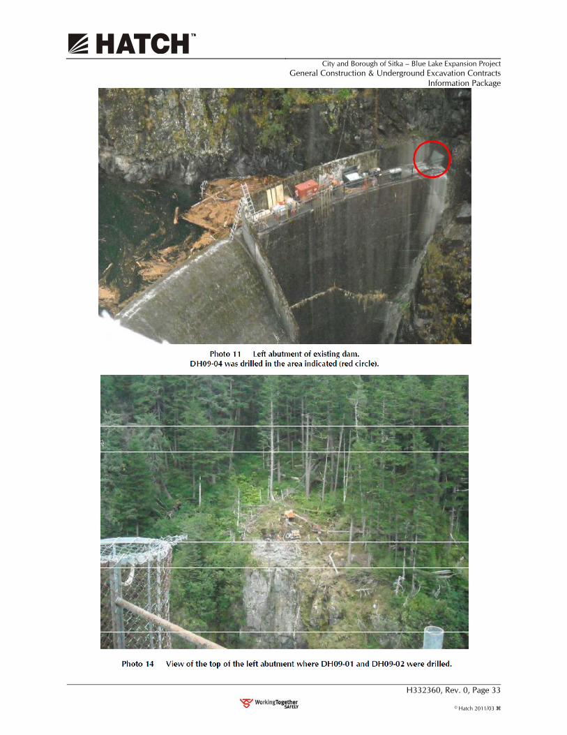
City and Borough of Sitka – Blue Lake Expansion Project
General Construction & Underground Excavation Contracts Information Package
H332360, Rev. 0, Page 33
© Hatch 2011/03

City and Borough of Sitka – Blue Lake Expansion Project
General Construction & Underground Excavation Contracts Information Package
H332360, Rev. 0, Page 34
© Hatch 2011/03

City and Borough of Sitka – Blue Lake Expansion Project
General Construction & Underground Excavation Contracts Information Package
H332360, Rev. 0, Page 35
© Hatch 2011/03
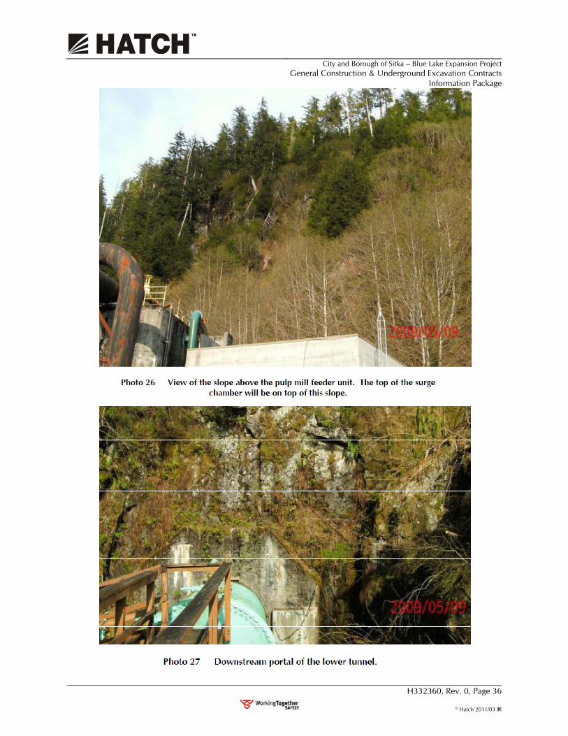
City and Borough of Sitka – Blue Lake Expansion Project
General Construction & Underground Excavation Contracts Information Package
H332360, Rev. 0, Page 36
© Hatch 2011/03

City and Borough of Sitka – Blue Lake Expansion Project
General Construction & Underground Excavation Contracts Information Package
H332360, Rev. 0, Page 37
© Hatch 2011/03

![ELECTRIC FT]Nil - Sitka, Alaska · CIry AND BOROUGH OF SITKA ELECTRIC FUND ITEMIZED REVENUES ACCOUNT# DESCRIPTION AMOUNT STATE REVENUE 300-310-3101.003 Diesel Surcharge $ 100,000](https://static.fdocuments.us/doc/165x107/5ea9e60fa991e920c7734d9e/electric-ftnil-sitka-ciry-and-borough-of-sitka-electric-fund-itemized-revenues.jpg)


