April 2, 2009 GTX LTD iS 255 and RXT™ iS 255 REVISION 3bweb.brp-jp.com/PDF/PWPD2009-3R3.pdf ·...
24
April 2, 2009 Subject: GTX † LTD iS 255 and RXT™ iS 255 Predelivery Inspection (All countries) No. 2009-3 R E V I S I O N 3 S e p t e m b e r 8 , 2 0 0 9 U N D E R L I N E T E X T ( S ) B E T W E E N A R R O W S I S ( A R E ) A D D E D E L E M E N T ( S ) T O T H E P R E V I O U S P U B L I C A T I O N . MODEL PACKAGE MODEL NUMBER ENGINE (HP) PREDELIVERY KIT SERIAL NUMBER 189A GTX † LTD iS 189B (Int'l) 1503 HO (255) 294 000 815 ALL 349A RXT™ iS 349B (Int'l) 1503 HO (255) 294 000 815 ALL GTX † is a trademark of Castrol Ltd. Used under license TABLE OF CONTENTS Page Page IMPORTANT NOTICE ....................... 2 UNCRATING .................................. 3 Crate Cover Removal .......................... 3 Watercraft Preparation ......................... 3 Releasing Moving Deck ....................... 5 PARTS TO BE INSTALLED ................. 6 Battery ........................................... 6 Boarding Step ................................... 8 Steering Column Installation .................. 9 Steering Cable .................................. 12 Storage Cover ................................... 12 Compliance Label ............................... 13 Watercraft Decal ................................ 13 Accessories ..................................... 13 FLUIDS ......................................... 13 General Guidelines ............................. 13 Fuel ............................................... 14 Engine Oil ........................................ 14 Engine Coolant .................................. 15 B.U.D.S. PROGRAMMING ................. 16 Connecting a PC to Watercraft ............... 16 B.U.D.S. Software .............................. 17 D.E.S.S. Key Programming .................... 18 Information Center Setup ..................... 20 Unlock iS Suspension .......................... 20 Ending a B.U.D.S. Session .................... 20 ADJUSTMENTS ............................. 21 Steering Alignment ............................. 21 FUEL SYSTEM PRESSURIZATION ...... 21 Fuel System Pressurization Procedure ...... 21 FINAL INSPECTION ......................... 21 O.T.A.S. Operation ............................. 21 Watercraft Test Run ............................ 22 Protective Films Removal ..................... 22 Watercraft Cleaning ............................ 22 Delivery to Customer .......................... 22 TECHNICAL DATA ........................... 23 Printed in Canada. (sbl2009-004_rev3 en AP) ©2009 Bombardier Recreational Products Inc. and BRP US Inc. All rights reserved. 1 / 24 ®™ and the BRP logo are trademarks of Bombardier Recreational Products Inc. or its affiliates.
Transcript of April 2, 2009 GTX LTD iS 255 and RXT™ iS 255 REVISION 3bweb.brp-jp.com/PDF/PWPD2009-3R3.pdf ·...
April 2, 2009 Subject:GTX† LTD iS 255 and RXT™ iS 255
Predelivery Inspection (All countries)
No. 2009-3REVISION 3
September 8,2009
UNDERLINE TEXT(S) BETWEEN ARROWS IS (ARE) ADDED ELEMENT(S) TOTHE PREVIOUS PUBLICATION.
MODEL PACKAGE MODEL NUMBER ENGINE (HP) PREDELIVERY KIT SERIAL NUMBER
189AGTX† LTD iS
189B (Int'l)1503 HO (255) 294 000 815 ALL
349ARXT™ iS
349B (Int'l)1503 HO (255) 294 000 815 ALL
GTX† is a trademark of Castrol Ltd. Used under license
TABLE OF CONTENTSPage Page
IMPORTANT NOTICE ..... . . . . . . . . . . . . . . . . . . 2
UNCRATING ...... . . . . . . . . . . . . . . . . . . . . . . . . . . . . 3Crate Cover Removal .. . . . . . . . . . . . . . . . . . . . . . . . . 3Watercraft Preparation.. . . . . . . . . . . . . . . . . . . . . . . . 3Releasing Moving Deck .. . . . . . . . . . . . . . . . . . . . . . 5
PARTS TO BE INSTALLED...... . . . . . . . . . . . 6Battery ... . . . . . . . . . . . . . . . . . . . . . . . . . . . . . . . . . . . . . . . . 6Boarding Step ... . . . . . . . . . . . . . . . . . . . . . . . . . . . . . . . . 8Steering Column Installation ... . . . . . . . . . . . . . . . 9Steering Cable .. . . . . . . . . . . . . . . . . . . . . . . . . . . . . . . . . 12Storage Cover ... . . . . . . . . . . . . . . . . . . . . . . . . . . . . . . . . 12Compliance Label.. . . . . . . . . . . . . . . . . . . . . . . . . . . . . . 13Watercraft Decal. . . . . . . . . . . . . . . . . . . . . . . . . . . . . . . . 13Accessories ... . . . . . . . . . . . . . . . . . . . . . . . . . . . . . . . . . . 13
FLUIDS...... . . . . . . . . . . . . . . . . . . . . . . . . . . . . . . . . . . . 13General Guidelines ... . . . . . . . . . . . . . . . . . . . . . . . . . . 13Fuel .. . . . . . . . . . . . . . . . . . . . . . . . . . . . . . . . . . . . . . . . . . . . . . 14Engine Oil. . . . . . . . . . . . . . . . . . . . . . . . . . . . . . . . . . . . . . . . 14Engine Coolant.. . . . . . . . . . . . . . . . . . . . . . . . . . . . . . . . . 15
B.U.D.S. PROGRAMMING...... . . . . . . . . . . . 16Connecting a PC to Watercraft .. . . . . . . . . . . . . . 16
B.U.D.S. Software .. . . . . . . . . . . . . . . . . . . . . . . . . . . . . 17D.E.S.S. Key Programming.. . . . . . . . . . . . . . . . . . . 18Information Center Setup ... . . . . . . . . . . . . . . . . . . 20Unlock iS Suspension ... . . . . . . . . . . . . . . . . . . . . . . . 20Ending a B.U.D.S. Session .. . . . . . . . . . . . . . . . . . . 20
ADJUSTMENTS ...... . . . . . . . . . . . . . . . . . . . . . . . 21Steering Alignment... . . . . . . . . . . . . . . . . . . . . . . . . . . 21
FUEL SYSTEM PRESSURIZATION ...... 21Fuel System Pressurization Procedure .. . . . . 21
FINAL INSPECTION ...... . . . . . . . . . . . . . . . . . . . 21O.T.A.S. Operation ... . . . . . . . . . . . . . . . . . . . . . . . . . . 21Watercraft Test Run... . . . . . . . . . . . . . . . . . . . . . . . . . 22Protective Films Removal . . . . . . . . . . . . . . . . . . . . . 22Watercraft Cleaning .. . . . . . . . . . . . . . . . . . . . . . . . . . . 22Delivery to Customer ... . . . . . . . . . . . . . . . . . . . . . . . 22
TECHNICAL DATA...... . . . . . . . . . . . . . . . . . . . . . 23
Printed in Canada. (sbl2009-004_rev3 en AP)©2009 Bombardier Recreational Products Inc. and BRP US Inc. All rights reserved.
1 / 24®™ and the BRP logo are trademarks of Bombardier Recreational Products Inc. or its affiliates.
IMPORTANT NOTICE
IMPORTANT NOTICEThis bulletin must be used in conjunction with the PREDELIVERY CHECK LIST enclosed in the shrinkpack.
WARNING
To obtain limited warranty coverage, predelivery procedures must be performed by an autho-rized Sea-Doo watercraft dealer/distributor. Apply all necessary torques as indicated.
— The information and components/system descriptions contained in this document are correct at thetime of publication. However, BRP maintains a policy of continuous improvement of its products withoutimposing upon itself any obligation to install them on products previously manufactured.
— Due to late changes, there might be some differences between the manufactured product and thedescriptions and/or specifications in this document. BRP reserves the right at any time to discontinue orchange specifications, designs, features, models or equipment without incurring obligation.
— The illustrations in this document show the typical construction of the different assemblies and maynot reproduce the full detail or exact shape of the parts; however, they represent parts that have thesame or similar function.
— The content of this bulletin is designed as a guideline only. All mechanics performing predelivery pro-cedures should have attended the current model year service training.
— Further information or inquiries should be directed to your distributor service representative and/orspecific SHOP MANUAL sections.
— Please complete the PREDELIVERY CHECK LIST for each watercraft and retain a purchaser signedcopy.
— Make sure the purchaser receives the OPERATORS GUIDE, PREDELIVERY CHECK LIST signed copyand SAFETY DVD.
WARNING
Torque wrench tightening specifications must be strictly adhered to. Where specified, install newlocking devices (e.g. lock tabs, elastic stop nuts). If the efficiency of a locking device is impaired,it must be renewed.
2 / 24 2009-3 PREDELIVERY
UNCRATING
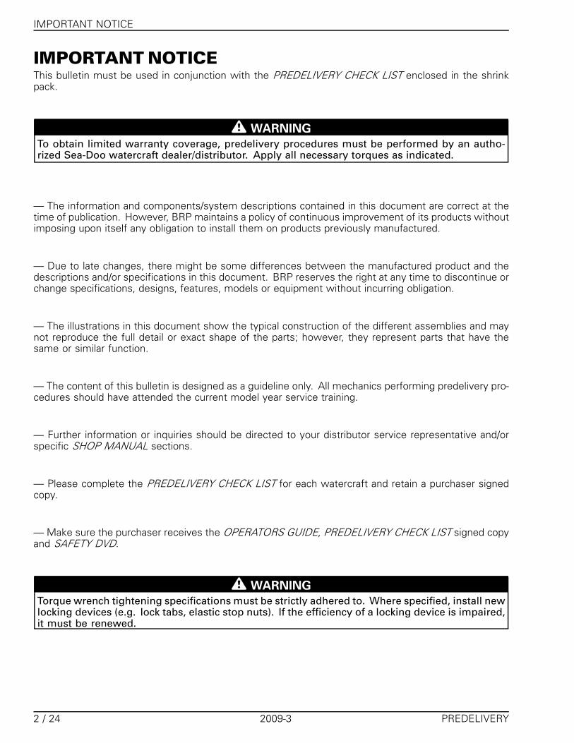
UNCRATINGCrate Cover Removal1. Carefully lay crate on its bottom.
NOTICE Allowing crate to drop may cause se-rious damage to watercraft.
2. Remove all screws retaining crate cover tocrate base.
NOTE: Screws that are used are Robertson† #2type that require the use of an appropriate screw-driver.3. Assisted by another person, lift up crate cover.4. Raise cover vertically from both ends at the
same time.
NOTICE Never tip cover toward the front orrear of the watercraft while lifting it.
� �
��������
TYPICAL1. Remove screws2. Raise cover vertically
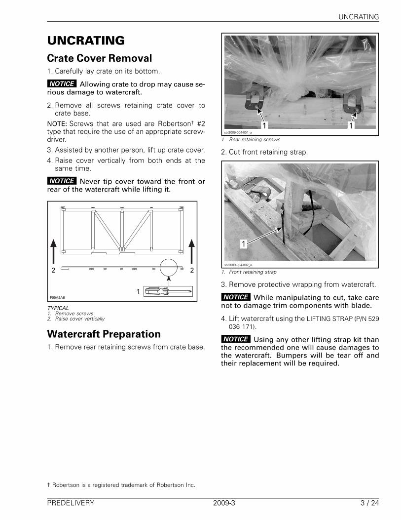
Watercraft Preparation1. Remove rear retaining screws from crate base.
sbl2009-004-001_a
1. Rear retaining screws
2. Cut front retaining strap.
sbl2009-004-002_a
1. Front retaining strap
3. Remove protective wrapping from watercraft.
NOTICE While manipulating to cut, take carenot to damage trim components with blade.
4. Lift watercraft using the LIFTING STRAP (P/N 529036 171).
NOTICE Using any other lifting strap kit thanthe recommended one will cause damages tothe watercraft. Bumpers will be tear off andtheir replacement will be required.
† Robertson is a registered trademark of Robertson Inc.
PREDELIVERY 2009-3 3 / 24
UNCRATING
sbl2009-004-003
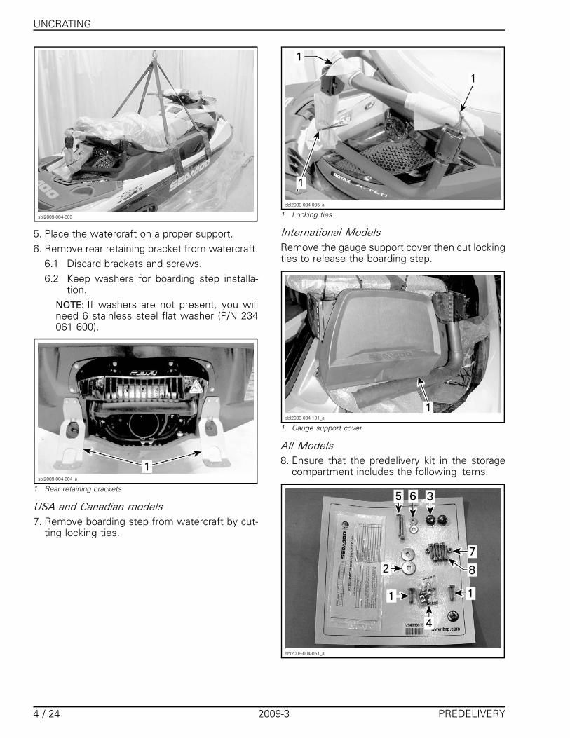
5. Place the watercraft on a proper support.6. Remove rear retaining bracket from watercraft.
6.1 Discard brackets and screws.6.2 Keep washers for boarding step installa-
tion.NOTE: If washers are not present, you willneed 6 stainless steel flat washer (P/N 234061 600).
sbl2009-004-004_a
1. Rear retaining brackets
USA and Canadian models7. Remove boarding step from watercraft by cut-
ting locking ties.
sbl2009-004-005_a
1. Locking ties
International ModelsRemove the gauge support cover then cut lockingties to release the boarding step.
sbl2009-004-101_a
1. Gauge support cover
All Models8. Ensure that the predelivery kit in the storage
compartment includes the following items.
sbl2009-004-051_a
4 / 24 2009-3 PREDELIVERY
UNCRATING
ITEM DESCRIPTION (P/N ) QTY
M8 x 25 screw (P/N 207 382 560)1 Refer to RELEASING MOVING DECK
subsection.2
M8 washer (P/N 250 200 011)2 Refer to RELEASING MOVING DECK
subsection.2
Plastic cap (P/N 291 002 950)3 Refer to RELEASING MOVING DECK
subsection.2
Battery hardware (P/N 250 000 282)4
Refer to BATTERY subsection.1
M6 x 45 bolt (P/N 207 164 560)5
Refer to BATTERY subsection.2
M6 washer (P/N 234 062 600)6
Refer to BATTERY subsection.2
M6 nut (P/N 232 561 200)7
Refer to BATTERY subsection.2
M6 x 25 screw (P/N 250 000 076)8 Refer to BOARDING STEP
subsection.6
Releasing Moving DeckNOTE: For transportation purpose, the movingdeck suspension has been completely com-pressed and secured at the factory using cable.Make sure to release tension and remove secur-ing cable from moving deck suspension prior toworking on the watercraft.
WARNING
The moving deck suspension is attached un-der tension (spring-loaded). Before releasingtension:– Clean moving deck of any objects and
tools.– Do not use pneumatic or electric tools for
removing moving deck retaining screws.– Adhere strictly to following procedure.
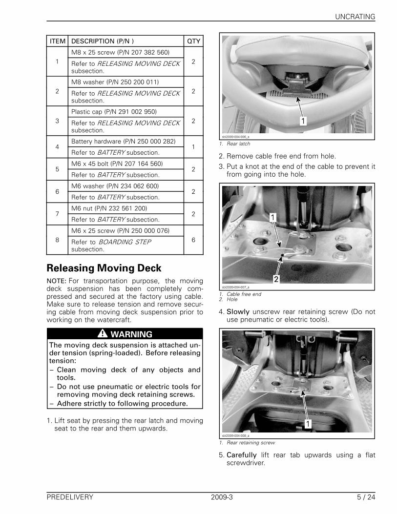
1. Lift seat by pressing the rear latch and movingseat to the rear and them upwards.
sbl2009-004-006_a
1. Rear latch
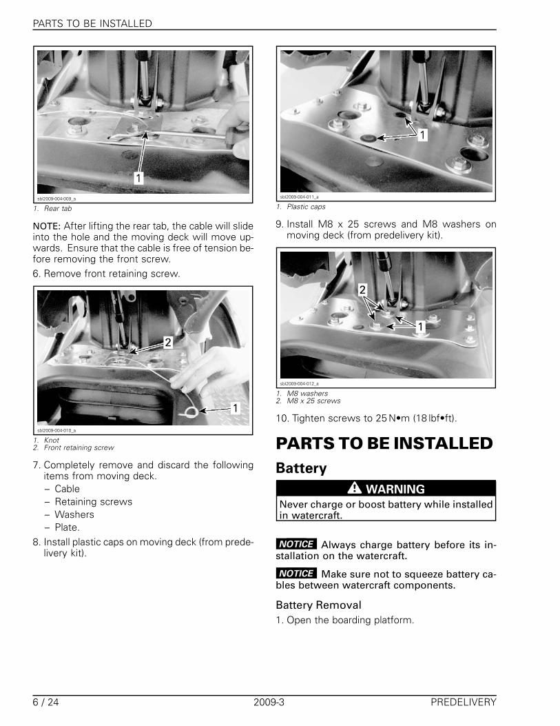
2. Remove cable free end from hole.3. Put a knot at the end of the cable to prevent it
from going into the hole.
sbl2009-004-007_a
1. Cable free end2. Hole
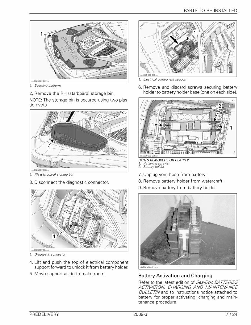
4. Slowly unscrew rear retaining screw (Do notuse pneumatic or electric tools).
sbl2009-004-008_a
1. Rear retaining screw
5. Carefully lift rear tab upwards using a flatscrewdriver.
PREDELIVERY 2009-3 5 / 24
PARTS TO BE INSTALLED
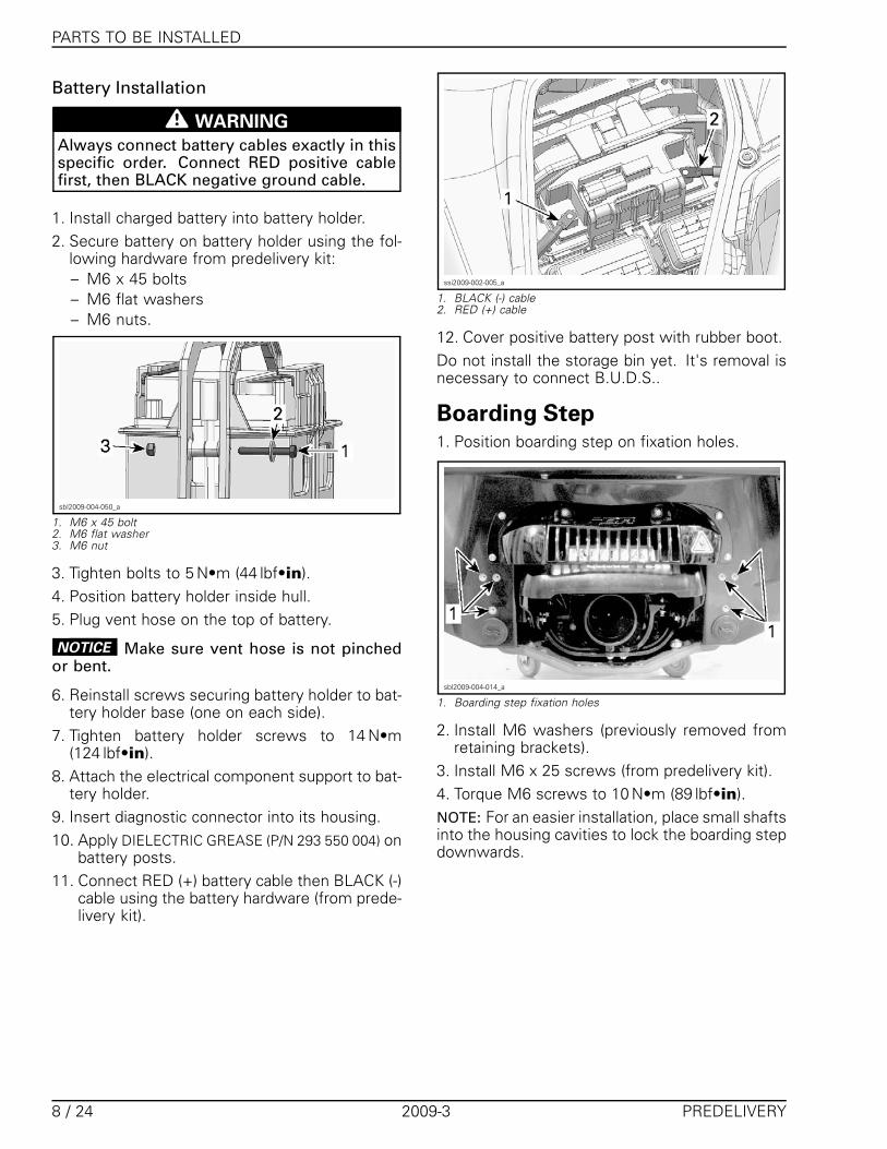
sbl2009-004-009_a
1. Rear tab
NOTE: After lifting the rear tab, the cable will slideinto the hole and the moving deck will move up-wards. Ensure that the cable is free of tension be-fore removing the front screw.6. Remove front retaining screw.
sbl2009-004-010_a
1. Knot2. Front retaining screw
7. Completely remove and discard the followingitems from moving deck.– Cable– Retaining screws– Washers– Plate.
8. Install plastic caps on moving deck (from prede-livery kit).
sbl2009-004-011_a
1. Plastic caps
9. Install M8 x 25 screws and M8 washers onmoving deck (from predelivery kit).
sbl2009-004-012_a
1. M8 washers2. M8 x 25 screws
10. Tighten screws to 25 N•m (18 lbf•ft).
PARTS TO BE INSTALLEDBattery
WARNING
Never charge or boost battery while installedin watercraft.
NOTICE Always charge battery before its in-stallation on the watercraft.
NOTICE Make sure not to squeeze battery ca-bles between watercraft components.
Battery Removal1. Open the boarding platform.
6 / 24 2009-3 PREDELIVERY
PARTS TO BE INSTALLED
ssi2009-002-002_a
1. Boarding platform
2. Remove the RH (starboard) storage bin.NOTE: The storage bin is secured using two plas-tic rivets
ssi2009-002-003_a
1. RH (starboard) storage bin
3. Disconnect the diagnostic connector.
ssi2009-002-004_a
1. Diagnostic connector
4. Lift and push the top of electrical componentsupport forward to unlock it from battery holder.
5. Move support aside to make room.
ssi2009-002-008_a
1. Electrical component support
6. Remove and discard screws securing batteryholder to battery holder base (one on each side).
ssi2009-002-009_a
PARTS REMOVED FOR CLARITY1. Retaining screws2. Battery holder
7. Unplug vent hose from battery.8. Remove battery holder from watercraft.9. Remove battery from battery holder.
sbl2009-004-013_a
Battery Activation and ChargingRefer to the latest edition of Sea-Doo BATTERIESACTIVATION, CHARGING AND MAINTENANCEBULLETIN and to instructions notice attached tobattery for proper activating, charging and main-tenance procedure.
PREDELIVERY 2009-3 7 / 24
PARTS TO BE INSTALLED
Battery Installation
WARNING
Always connect battery cables exactly in thisspecific order. Connect RED positive cablefirst, then BLACK negative ground cable.
1. Install charged battery into battery holder.2. Secure battery on battery holder using the fol-
lowing hardware from predelivery kit:– M6 x 45 bolts– M6 flat washers– M6 nuts.
sbl2009-004-050_a
1. M6 x 45 bolt2. M6 flat washer3. M6 nut
3. Tighten bolts to 5 N•m (44 lbf•in).4. Position battery holder inside hull.5. Plug vent hose on the top of battery.
NOTICE Make sure vent hose is not pinchedor bent.
6. Reinstall screws securing battery holder to bat-tery holder base (one on each side).
7. Tighten battery holder screws to 14 N•m(124 lbf•in).
8. Attach the electrical component support to bat-tery holder.
9. Insert diagnostic connector into its housing.10. Apply DIELECTRIC GREASE (P/N 293 550 004) on
battery posts.11. Connect RED (+) battery cable then BLACK (-)
cable using the battery hardware (from prede-livery kit).
ssi2009-002-005_a
1. BLACK (-) cable2. RED (+) cable
12. Cover positive battery post with rubber boot.Do not install the storage bin yet. It's removal isnecessary to connect B.U.D.S..
Boarding Step1. Position boarding step on fixation holes.
sbl2009-004-014_a
1. Boarding step fixation holes
2. Install M6 washers (previously removed fromretaining brackets).
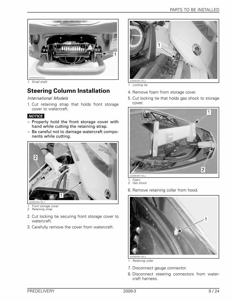
3. Install M6 x 25 screws (from predelivery kit).4. Torque M6 screws to 10 N•m (89 lbf•in).NOTE: For an easier installation, place small shaftsinto the housing cavities to lock the boarding stepdownwards.
8 / 24 2009-3 PREDELIVERY
PARTS TO BE INSTALLED
sbl2009-004-015_a
1. Small shaft
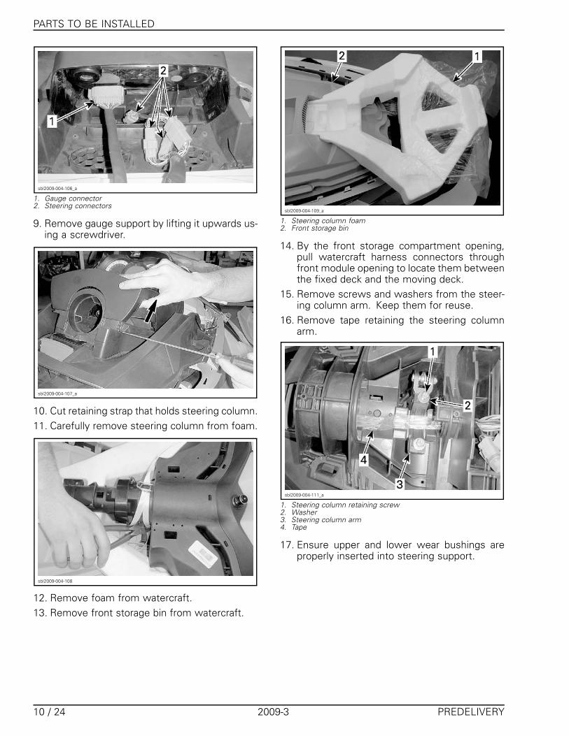
Steering Column InstallationInternational Models1. Cut retaining strap that holds front storage
cover to watercraft.
NOTICE
– Properly hold the front storage cover withhand while cutting the retaining strap.
– Be careful not to damage watercraft compo-nents while cutting.
sbl2009-004-102_a
1. Front storage cover2. Retaining strap
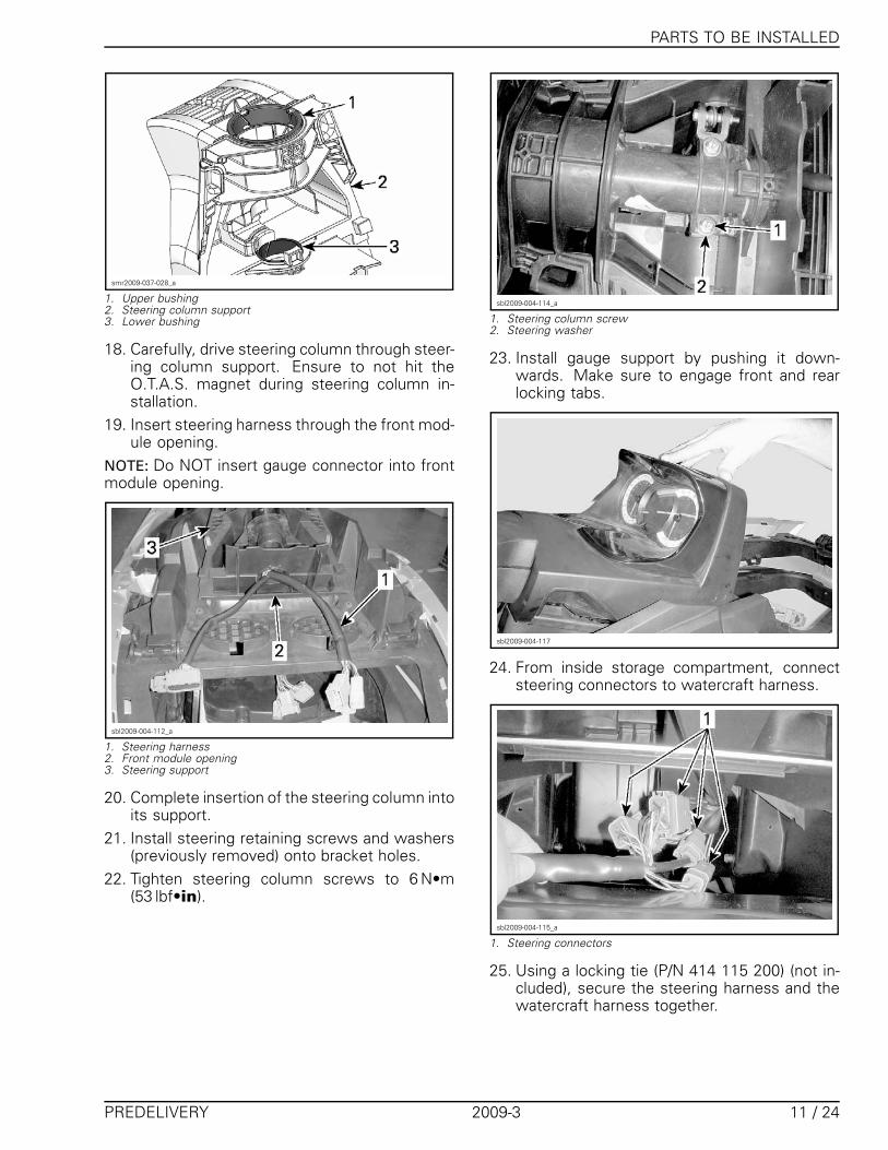
2. Cut locking tie securing front storage cover towatercraft.
3. Carefully remove the cover from watercraft.
sbl2009-004-103_a
1. Locking tie
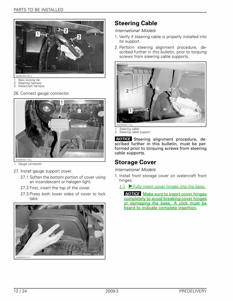
4. Remove foam from storage cover.5. Cut locking tie that holds gas shock to storage
cover.
sbl2009-004-104_a
1. Foam2. Gas shock
6. Remove retaining collar from hood.
sbl2009-004-105_a
1. Retaining collar
7. Disconnect gauge connector.8. Disconnect steering connectors from water-
craft harness.
PREDELIVERY 2009-3 9 / 24
PARTS TO BE INSTALLED
sbl2009-004-106_a
1. Gauge connector2. Steering connectors
9. Remove gauge support by lifting it upwards us-ing a screwdriver.
sbl2009-004-107_a
10. Cut retaining strap that holds steering column.11. Carefully remove steering column from foam.
sbl2009-004-108
12. Remove foam from watercraft.13. Remove front storage bin from watercraft.
sbl2009-004-109_a
1. Steering column foam2. Front storage bin
14. By the front storage compartment opening,pull watercraft harness connectors throughfront module opening to locate them betweenthe fixed deck and the moving deck.
15. Remove screws and washers from the steer-ing column arm. Keep them for reuse.
16. Remove tape retaining the steering columnarm.
sbl2009-004-111_a
1. Steering column retaining screw2. Washer3. Steering column arm4. Tape
17. Ensure upper and lower wear bushings areproperly inserted into steering support.
10 / 24 2009-3 PREDELIVERY
PARTS TO BE INSTALLED
smr2009-037-028_a
1. Upper bushing2. Steering column support3. Lower bushing
18. Carefully, drive steering column through steer-ing column support. Ensure to not hit theO.T.A.S. magnet during steering column in-stallation.
19. Insert steering harness through the front mod-ule opening.
NOTE: Do NOT insert gauge connector into frontmodule opening.
sbl2009-004-112_a
1. Steering harness2. Front module opening3. Steering support
20. Complete insertion of the steering column intoits support.
21. Install steering retaining screws and washers(previously removed) onto bracket holes.
22. Tighten steering column screws to 6 N•m(53 lbf•in).
sbl2009-004-114_a
1. Steering column screw2. Steering washer
23. Install gauge support by pushing it down-wards. Make sure to engage front and rearlocking tabs.
sbl2009-004-117
24. From inside storage compartment, connectsteering connectors to watercraft harness.
sbl2009-004-115_a
1. Steering connectors
25. Using a locking tie (P/N 414 115 200) (not in-cluded), secure the steering harness and thewatercraft harness together.
PREDELIVERY 2009-3 11 / 24
PARTS TO BE INSTALLED
sbl2009-004-150_a
1. New locking tie2. Steering harness3. Watercraft harness
26. Connect gauge connector.
sbl2009-004-116_a
1. Gauge connector
27. Install gauge support cover.27.1 Soften the bottom portion of cover using
an incandescent or halogen light.27.2 First, insert the top of the cover.27.3 Press both lower sides of cover to lock
tabs.
sbl2009-004-118
Steering CableInternational Models1. Verify if steering cable is properly installed into
its support.2. Perform steering alignment procedure, de-
scribed further in this bulletin, prior to torquingscrews from steering cable supports.
sbl2009-004-119_a
1. Steering cable2. Steering cable support
NOTICE Steering alignment procedure, de-scribed further in this bulletin, must be per-formed prior to torquing screws from steeringcable supports.
Storage CoverInternational Models1. Install front storage cover on watercraft front
hinges.1.1 Fully insert cover hinges into the base.
NOTICE Make sure to insert cover hingescompletely to avoid breaking cover hingesor damaging the base. A click must beheard to indicate complete insertion.
12 / 24 2009-3 PREDELIVERY
FLUIDS
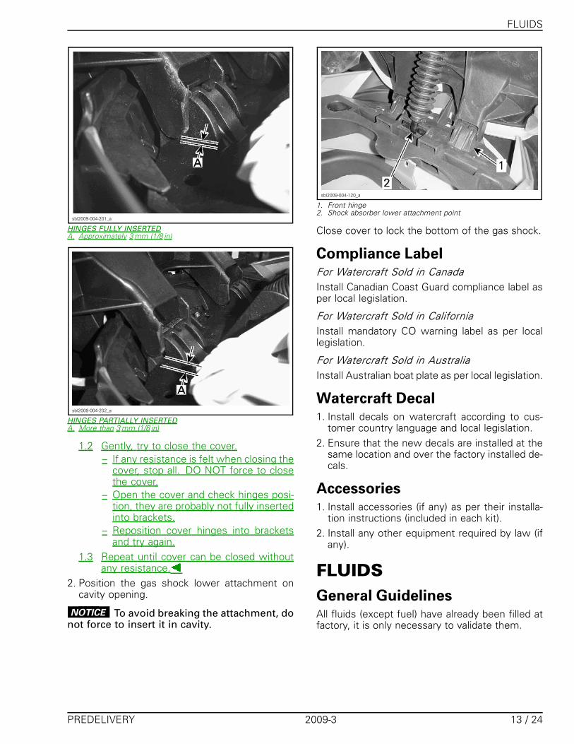
sbl2009-004-201_a
HINGES FULLY INSERTEDA. Approximately 3 mm (1/8 in)
sbl2009-004-202_a
HINGES PARTIALLY INSERTEDA. More than 3 mm (1/8 in)
1.2 Gently, try to close the cover.– If any resistance is felt when closing the
cover, stop all. DO NOT force to closethe cover.
– Open the cover and check hinges posi-tion, they are probably not fully insertedinto brackets.
– Reposition cover hinges into bracketsand try again.
1.3 Repeat until cover can be closed withoutany resistance.
2. Position the gas shock lower attachment oncavity opening.
NOTICE To avoid breaking the attachment, donot force to insert it in cavity.
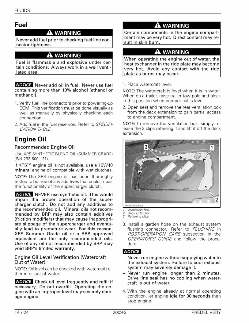
sbl2009-004-120_a
1. Front hinge2. Shock absorber lower attachment point
Close cover to lock the bottom of the gas shock.
Compliance LabelFor Watercraft Sold in CanadaInstall Canadian Coast Guard compliance label asper local legislation.
For Watercraft Sold in CaliforniaInstall mandatory CO warning label as per locallegislation.
For Watercraft Sold in AustraliaInstall Australian boat plate as per local legislation.
Watercraft Decal1. Install decals on watercraft according to cus-
tomer country language and local legislation.2. Ensure that the new decals are installed at the
same location and over the factory installed de-cals.
Accessories1. Install accessories (if any) as per their installa-
tion instructions (included in each kit).2. Install any other equipment required by law (if
any).
FLUIDSGeneral GuidelinesAll fluids (except fuel) have already been filled atfactory, it is only necessary to validate them.
PREDELIVERY 2009-3 13 / 24
FLUIDS
Fuel
WARNING
Never add fuel prior to checking fuel line con-nector tightness.
WARNING
Fuel is flammable and explosive under cer-tain conditions. Always work in a well venti-lated area.
NOTICE Never add oil in fuel. Never use fuelcontaining more than 10% alcohol (ethanol ormethanol).
1. Verify fuel line connectors prior to powering-upECM. This verification must be done visually aswell as manually by physically checking eachconnection.
2. Add fuel in the fuel reservoir. Refer to SPECIFI-CATION TABLE.
Engine OilRecommended Engine OilUse XPS SYNTHETIC BLEND OIL (SUMMER GRADE)(P/N 293 600 121).If XPS™ engine oil is not available, use a 10W40mineral engine oil compatible with wet clutches.NOTE: The XPS engine oil has been thoroughlytested to be free of any additives that could impairthe functionality of the supercharger clutch.
NOTICE NEVER use synthetic oil. This wouldimpair the proper operation of the super-charger clutch. Do not add any additives tothe recommended oil. Mineral oils not recom-mended by BRP may also contain additives(friction modifiers) that may cause inappropri-ate slippage of the supercharger and eventu-ally lead to premature wear. For this reason,XPS Summer Grade oil or a BRP approvedequivalent are the only recommended oils.Use of any oil not recommended by BRP mayvoid BRP's limited warranty.
Engine Oil Level Verification (WatercraftOut of Water)NOTE: Oil level can be checked with watercraft ei-ther in or out of water.
NOTICE Check oil level frequently and refill ifnecessary. Do not overfill. Operating the en-gine with an improper level may severely dam-age engine.
WARNING
Certain components in the engine compart-ment may be very hot. Direct contact may re-sult in skin burn.
WARNING
When operating the engine out of water, theheat exchanger in the ride plate may becomevery hot. Avoid any contact with the rideplate as burns may occur.
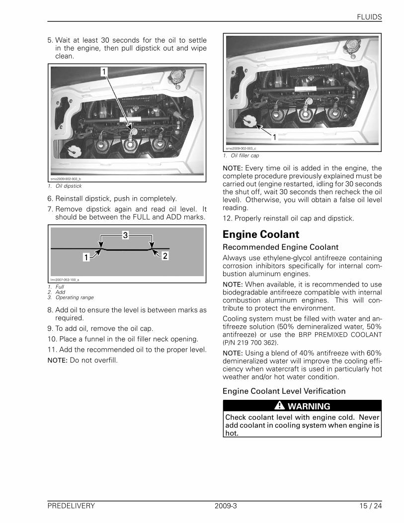
1. Place watercraft level.NOTE: The watercraft is level when it is in water.When on a trailer, raise trailer tow pole and blockin this position when bumper rail is level.2. Open seat and remove the rear ventilation box
from the deck extension to gain partial accessto engine compartment.
NOTE: To remove the ventilation box, simply re-lease the 3 clips retaining it and lift it off the deckextension.
smo2009-002-002_a
1. Ventilation Box2. Deck Extension3. Retaining clips
3. Install a garden hose on the exhaust systemflushing connector. Refer to FLUSHING inPOST-OPERATION CARE subsection in theOPERATOR'S GUIDE and follow the proce-dure.
NOTICE
– Never run engine without supplying water tothe exhaust system. Failure to cool exhaustsystem may severely damage it.
– Never run engine longer than 2 minutes.Drive line seal has no cooling when water-craft is out of water.
4. With the engine already at normal operatingcondition, let engine idle for 30 seconds thenstop engine.
14 / 24 2009-3 PREDELIVERY
FLUIDS
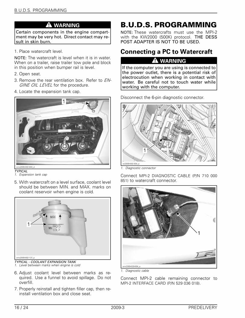
5. Wait at least 30 seconds for the oil to settlein the engine, then pull dipstick out and wipeclean.
smo2009-002-003_b
1. Oil dipstick
6. Reinstall dipstick, push in completely.7. Remove dipstick again and read oil level. It
should be between the FULL and ADD marks.
lmr2007-053-100_a
1. Full2. Add3. Operating range
8. Add oil to ensure the level is between marks asrequired.
9. To add oil, remove the oil cap.10. Place a funnel in the oil filler neck opening.11. Add the recommended oil to the proper level.NOTE: Do not overfill.
smo2009-002-003_c
1. Oil filler cap
NOTE: Every time oil is added in the engine, thecomplete procedure previously explained must becarried out (engine restarted, idling for 30 secondsthe shut off, wait 30 seconds then recheck the oillevel). Otherwise, you will obtain a false oil levelreading.12. Properly reinstall oil cap and dipstick.
Engine CoolantRecommended Engine CoolantAlways use ethylene-glycol antifreeze containingcorrosion inhibitors specifically for internal com-bustion aluminum engines.NOTE: When available, it is recommended to usebiodegradable antifreeze compatible with internalcombustion aluminum engines. This will con-tribute to protect the environment.Cooling system must be filled with water and an-tifreeze solution (50% demineralized water, 50%antifreeze) or use the BRP PREMIXED COOLANT(P/N 219 700 362).NOTE: Using a blend of 40% antifreeze with 60%demineralized water will improve the cooling effi-ciency when watercraft is used in particularly hotweather and/or hot water condition.
Engine Coolant Level Verification
WARNING
Check coolant level with engine cold. Neveradd coolant in cooling system when engine ishot.
PREDELIVERY 2009-3 15 / 24
B.U.D.S. PROGRAMMING
WARNING
Certain components in the engine compart-ment may be very hot. Direct contact may re-sult in skin burn.
1. Place watercraft level.NOTE: The watercraft is level when it is in water.When on a trailer, raise trailer tow pole and blockin this position when bumper rail is level.2. Open seat.3. Remove the rear ventilation box. Refer to EN-
GINE OIL LEVEL for the procedure.4. Locate the expansion tank cap.
smo2009-002-003_d
TYPICAL1. Expansion tank cap
5. With watercraft on a level surface, coolant levelshould be between MIN. and MAX. marks oncoolant reservoir when engine is cold.
smo2009-002-137_a
TYPICAL - COOLANT EXPANSION TANK1. Level between marks when engine is cold
6. Adjust coolant level between marks as re-quired. Use a funnel to avoid spillage. Do notoverfill.
7. Properly reinstall and tighten filler cap, then re-install ventilation box and close seat.
B.U.D.S. PROGRAMMINGNOTE: These watercrafts must use the MPI-2with the KW2000 (500K) protocol. THE DESSPOST ADAPTER IS NOT TO BE USED.
Connecting a PC to Watercraft
WARNING
If the computer you are using is connected tothe power outlet, there is a potential risk ofelectrocution when working in contact withwater. Be careful not to touch water whileworking with the computer.
Disconnect the 6-pin diagnostic connector.
ssi2009-002-004_a
1. Diagnostic connector
Connect MPI-2 DIAGNOSTIC CABLE (P/N 710 000851) to watercraft connector.
smr2009-028-004_a
1. Diagnostic cable
Connect MPI-2 cable remaining connector toMPI-2 INTERFACE CARD (P/N 529 036 018).
16 / 24 2009-3 PREDELIVERY
B.U.D.S. PROGRAMMING
vdd2006-001-151
NOTE: An optional MALE-FEMALE EXTENSION SE-RIAL CABLE (P/N DB9) available at electronic retailoutlets can be used between diagnostic cableand MPI-2 interface. Do not exceed 7.6 m (25 ft),communication errors may occur when using acable that this too long.Connect remaining MPI-2 interface card connec-tor to the USB port of a PC (personal computer).
mmr2006-079-200
Use B.U.D.S. software as described further inB.U.D.S. SOFTWARE.
B.U.D.S. SoftwareIMPORTANT: Ensure all connections have beenmade before starting B.U.D.S. to allow properoperation.Always use the latest appropriate version ofB.U.D.S. available on BOSSWeb.Connect D.E.S.S. key to watercraft D.E.S.S. post.Briefly press the start/stop button to power theECM. Engine must not crank.
IMPORTANT
Approximately 3 minutes after pressing thestart/stop button, the ECM will stop communicatingwith B.U.D.S. Therefore, operations with B.U.D.S.will be interrupted.
To initiate back the communication, briefly pressthe start/stop button. Do not hold start/stopbutton to avoid engine starting.
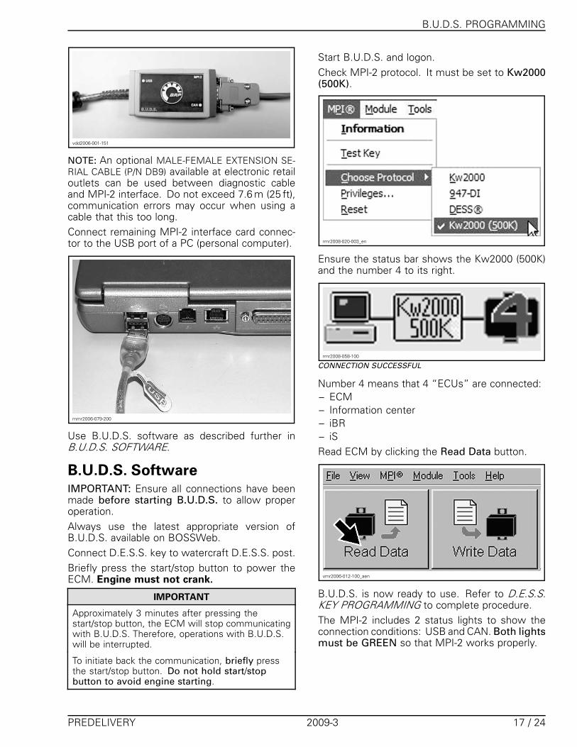
Start B.U.D.S. and logon.Check MPI-2 protocol. It must be set to Kw2000(500K).
rmr2008-020-003_en
Ensure the status bar shows the Kw2000 (500K)and the number 4 to its right.
rmr2008-058-100
CONNECTION SUCCESSFUL
Number 4 means that 4 “ECUs” are connected:– ECM– Information center– iBR– iSRead ECM by clicking the Read Data button.
vmr2006-012-100_aen
B.U.D.S. is now ready to use. Refer to D.E.S.S.KEY PROGRAMMING to complete procedure.The MPI-2 includes 2 status lights to show theconnection conditions: USB and CAN. Both lightsmust be GREEN so that MPI-2 works properly.
PREDELIVERY 2009-3 17 / 24
B.U.D.S. PROGRAMMING
vdd2006-001-151_b
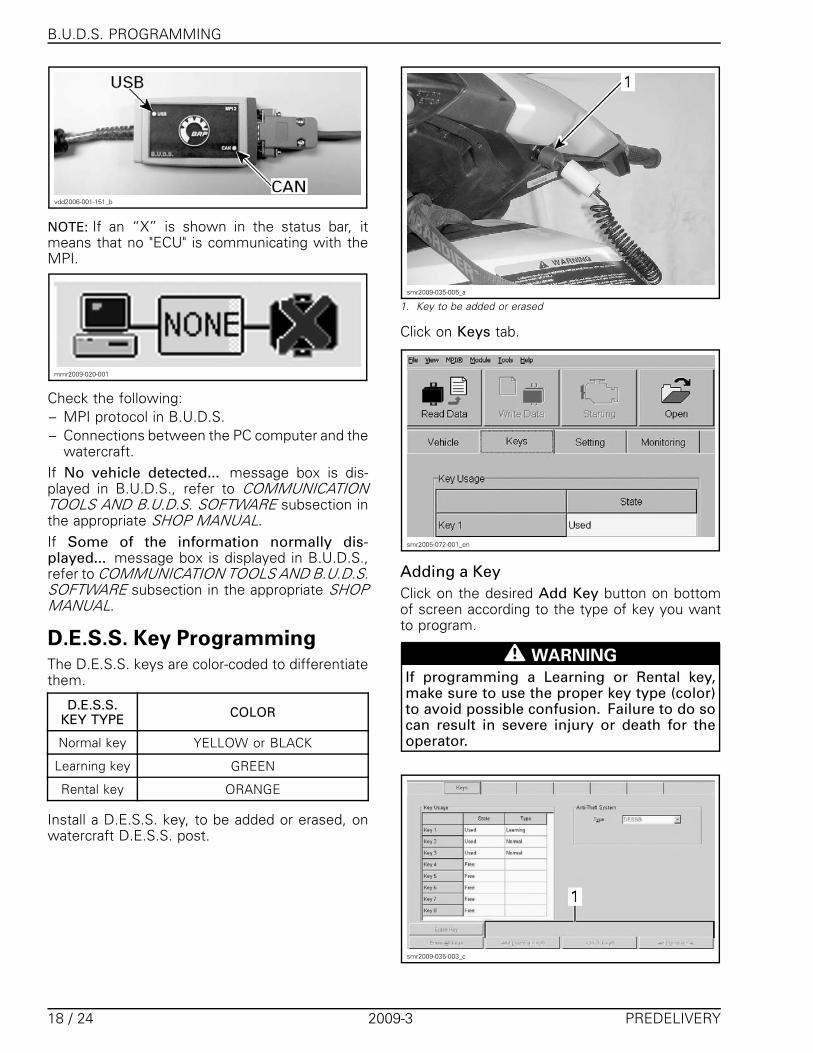
NOTE: If an “X” is shown in the status bar, itmeans that no "ECU" is communicating with theMPI.
mmr2009-020-001
Check the following:– MPI protocol in B.U.D.S.– Connections between the PC computer and the
watercraft.If No vehicle detected... message box is dis-played in B.U.D.S., refer to COMMUNICATIONTOOLS AND B.U.D.S. SOFTWARE subsection inthe appropriate SHOP MANUAL.If Some of the information normally dis-played... message box is displayed in B.U.D.S.,refer to COMMUNICATION TOOLS AND B.U.D.S.SOFTWARE subsection in the appropriate SHOPMANUAL.
D.E.S.S. Key ProgrammingThe D.E.S.S. keys are color-coded to differentiatethem.
D.E.S.S.KEY TYPE COLOR
Normal key YELLOW or BLACK
Learning key GREEN
Rental key ORANGE
Install a D.E.S.S. key, to be added or erased, onwatercraft D.E.S.S. post.
smr2009-035-005_a
1. Key to be added or erased
Click on Keys tab.
smr2005-072-001_en
Adding a KeyClick on the desired Add Key button on bottomof screen according to the type of key you wantto program.
WARNING
If programming a Learning or Rental key,make sure to use the proper key type (color)to avoid possible confusion. Failure to do socan result in severe injury or death for theoperator.
smr2009-035-003_c
18 / 24 2009-3 PREDELIVERY
B.U.D.S. PROGRAMMING
After approximately 10 seconds, the followingwindow will pop up confirming the new key hasbeen saved in the PC computer.
smr2008-020-008
If programming is complete, write the changes tothe ECM. Refer to WRITING CHANGES TO ECMin this subsection.
Adding another KeyRemove the key on D.E.S.S. post.Install the next key to be programmed on D.E.S.S.post.Click on the desired Add Key button.If programming is complete, write the changes tothe ECM. Refer to WRITING CHANGES TO ECMin this subsection.
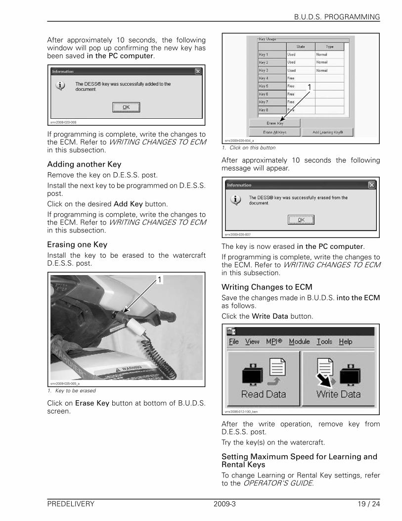
Erasing one KeyInstall the key to be erased to the watercraftD.E.S.S. post.
smr2009-035-005_a
1. Key to be erased
Click on Erase Key button at bottom of B.U.D.S.screen.
smr2009-035-004_a
1. Click on this button
After approximately 10 seconds the followingmessage will appear.
smr2009-035-007
The key is now erased in the PC computer.If programming is complete, write the changes tothe ECM. Refer to WRITING CHANGES TO ECMin this subsection.
Writing Changes to ECMSave the changes made in B.U.D.S. into the ECMas follows.Click the Write Data button.
vmr2006-012-100_ben
After the write operation, remove key fromD.E.S.S. post.Try the key(s) on the watercraft.
Setting Maximum Speed for Learning andRental KeysTo change Learning or Rental Key settings, referto the OPERATOR'S GUIDE.
PREDELIVERY 2009-3 19 / 24
B.U.D.S. PROGRAMMING
Information Center SetupSelect the Read Data button.Choose the Setting tab at the top of the page.At the bottom LH side of the setting page, selectthe Cluster tab.
smr2009-036-001_a
1. Read Data2. Setting tab3. Cluster tab
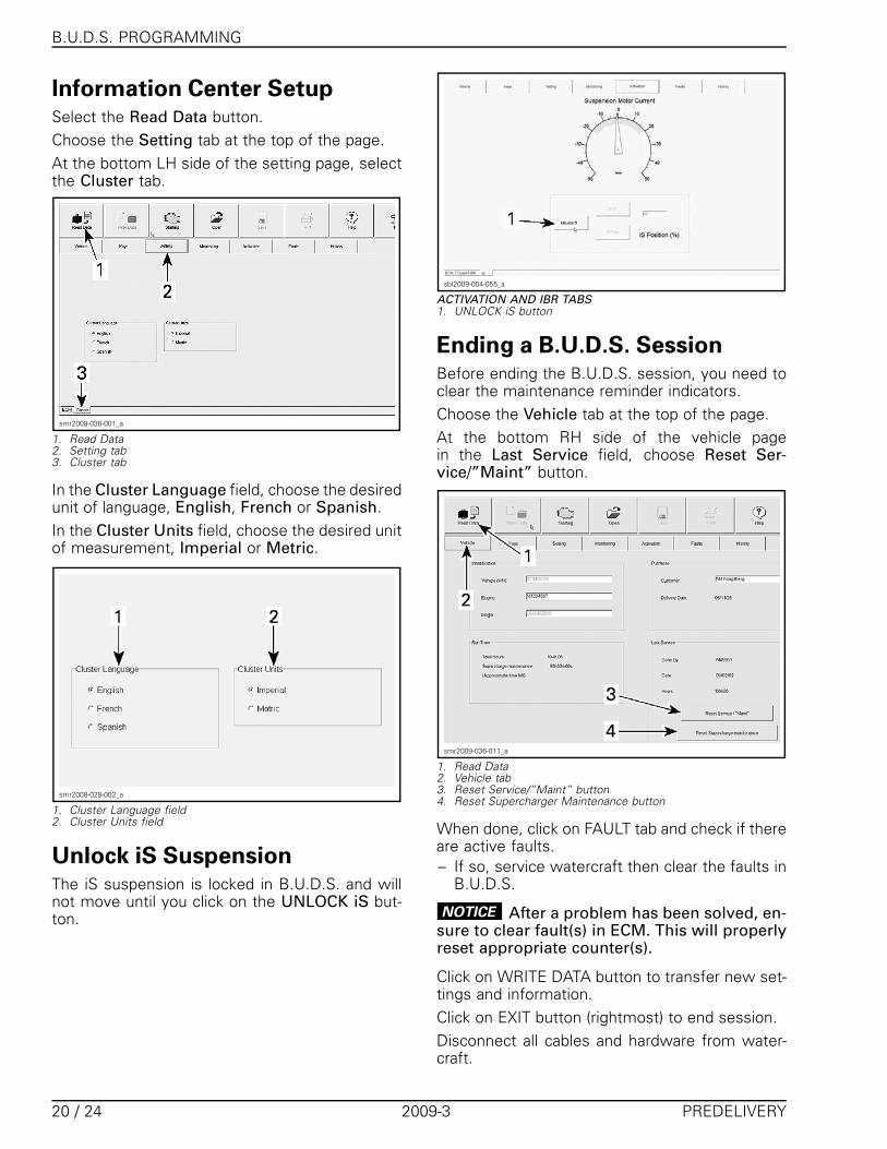
In the Cluster Language field, choose the desiredunit of language, English, French or Spanish.In the Cluster Units field, choose the desired unitof measurement, Imperial or Metric.
smr2008-028-002_a
1. Cluster Language field2. Cluster Units field
Unlock iS SuspensionThe iS suspension is locked in B.U.D.S. and willnot move until you click on the UNLOCK iS but-ton.
sbl2009-004-055_a
ACTIVATION AND IBR TABS1. UNLOCK iS button
Ending a B.U.D.S. SessionBefore ending the B.U.D.S. session, you need toclear the maintenance reminder indicators.Choose the Vehicle tab at the top of the page.At the bottom RH side of the vehicle pagein the Last Service field, choose Reset Ser-vice/”Maint” button.
smr2009-036-011_a
1. Read Data2. Vehicle tab3. Reset Service/”Maint” button4. Reset Supercharger Maintenance button
When done, click on FAULT tab and check if thereare active faults.– If so, service watercraft then clear the faults in
B.U.D.S.
NOTICE After a problem has been solved, en-sure to clear fault(s) in ECM. This will properlyreset appropriate counter(s).
Click on WRITE DATA button to transfer new set-tings and information.Click on EXIT button (rightmost) to end session.Disconnect all cables and hardware from water-craft.
20 / 24 2009-3 PREDELIVERY
FINAL INSPECTION
Ensure to reinstall cap over the communicationconnector and all watercraft parts.
ADJUSTMENTSSteering AlignmentInstall two bungee cords to maintain steering dur-ing the procedure.Position steering so that the edge of the steeringcolumn cover and edge of the gauge support areequal.
smr2009-037-055_a
1. Steering column cover edge2. Gauge support edge
Check jet pump nozzle position by placing astraight edge on nozzle outer end. Measure thedistance on each side of the straight edge. Itmust be equalled.
smr2009-037-003_a
1. Straight edge places against nozzle
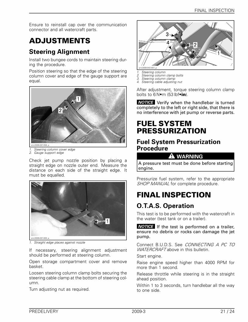
If necessary, steering alignment adjustmentshould be performed at steering column.Open storage compartment cover and removebasket.Loosen steering column clamp bolts securing thesteering cable clamp at the bottom of steering col-umn.Turn adjusting nut as required.
smr2009-042-007_a
1. Steering column2. Steering column clamp bolts3. Steering column clamp4. Steering cable adjusting nut
After adjustment, torque steering column clampbolts to 6 N•m (53 lbf•in).
NOTICE Verify when the handlebar is turnedcompletely to the left or right side, that there isno interference with jet pump or reverse parts.
FUEL SYSTEMPRESSURIZATIONFuel System PressurizationProcedure
WARNING
A pressure test must be done before startingengine.
Pressurize fuel system, refer to the appropriateSHOP MANUAL for complete procedure.
FINAL INSPECTIONO.T.A.S. OperationThis test is to be performed with the watercraft inthe water (test tank or on a trailer).
NOTICE If the test is performed on a trailer,ensure no debris or rocks can damage the jetpump.
Connect B.U.D.S. See CONNECTING A PC TOWATERCRAFT above in this bulletin.Start engine.Raise engine speed higher than 4000 RPM formore than 1 second.Release throttle while steering is in the straightahead position.Within 1 to 3 seconds, turn handlebar all the wayto one side.
PREDELIVERY 2009-3 21 / 24
FINAL INSPECTION
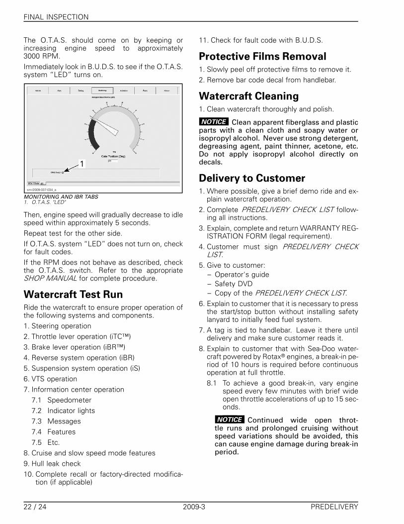
The O.T.A.S. should come on by keeping orincreasing engine speed to approximately3000 RPM.Immediately look in B.U.D.S. to see if the O.T.A.S.system “LED” turns on.
smr2009-037-034_a
MONITORING AND IBR TABS1. O.T.A.S. "LED"
Then, engine speed will gradually decrease to idlespeed within approximately 5 seconds.Repeat test for the other side.If O.T.A.S. system “LED” does not turn on, checkfor fault codes.If the RPM does not behave as described, checkthe O.T.A.S. switch. Refer to the appropriateSHOP MANUAL for complete procedure.
Watercraft Test RunRide the watercraft to ensure proper operation ofthe following systems and components.1. Steering operation2. Throttle lever operation (iTC™)3. Brake lever operation (iBR™)4. Reverse system operation (iBR)5. Suspension system operation (iS)6. VTS operation7. Information center operation
7.1 Speedometer7.2 Indicator lights7.3 Messages7.4 Features7.5 Etc.
8. Cruise and slow speed mode features9. Hull leak check10. Complete recall or factory-directed modifica-
tion (if applicable)
11. Check for fault code with B.U.D.S.
Protective Films Removal1. Slowly peel off protective films to remove it.2. Remove bar code decal from handlebar.
Watercraft Cleaning1. Clean watercraft thoroughly and polish.
NOTICE Clean apparent fiberglass and plasticparts with a clean cloth and soapy water orisopropyl alcohol. Never use strong detergent,degreasing agent, paint thinner, acetone, etc.Do not apply isopropyl alcohol directly ondecals.
Delivery to Customer1. Where possible, give a brief demo ride and ex-
plain watercraft operation.2. Complete PREDELIVERY CHECK LIST follow-
ing all instructions.3. Explain, complete and return WARRANTY REG-
ISTRATION FORM (legal requirement).4. Customer must sign PREDELIVERY CHECK
LIST.5. Give to customer:
– Operator's guide– Safety DVD– Copy of the PREDELIVERY CHECK LIST.
6. Explain to customer that it is necessary to pressthe start/stop button without installing safetylanyard to initially feed fuel system.
7. A tag is tied to handlebar. Leave it there untildelivery and make sure customer reads it.
8. Explain to customer that with Sea-Doo water-craft powered by Rotax® engines, a break-in pe-riod of 10 hours is required before continuousoperation at full throttle.8.1 To achieve a good break-in, vary engine
speed every few minutes with brief wideopen throttle accelerations of up to 15 sec-onds.
NOTICE Continued wide open throt-tle runs and prolonged cruising withoutspeed variations should be avoided, thiscan cause engine damage during break-inperiod.
22 / 24 2009-3 PREDELIVERY
TECHNICAL DATA
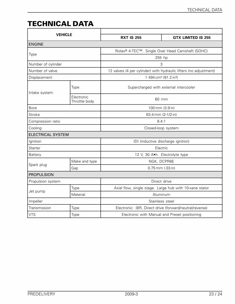
TECHNICAL DATAVEHICLE
RXT IS 255 GTX LIMITED IS 255
ENGINE
Rotax® 4-TEC™. Single Over Head Camshaft (SOHC)Type
255 hp
Number of cylinder 3
Number of valve 12 valves (4 per cylinder) with hydraulic lifters (no adjustment)
Displacement 1 494 cm³ (91.2 in³)
Type Supercharged with external intercoolerIntake system
ElectronicThrottle body 60 mm
Bore 100 mm (3.9 in)
Stroke 63.4 mm (2-1/2 in)
Compression ratio 8.4:1
Cooling Closed-loop system
ELECTRICAL SYSTEM
Ignition IDI (inductive discharge ignition)
Starter Electric
Battery 12 V, 30 A•h. Electrolyte type
Make and type NGK, DCPR8ESpark plug
Gap 0.75 mm (.03 in)
PROPULSION
Propulsion system Direct drive
Type Axial flow, single stage. Large hub with 10-vane statorJet pump
Material Aluminum
Impeller Stainless steel
Transmission Type Electronic: iBR, Direct drive (forward/neutral/reverse)
VTS Type Electronic with Manual and Preset positioning
PREDELIVERY 2009-3 23 / 24
TECHNICAL DATA
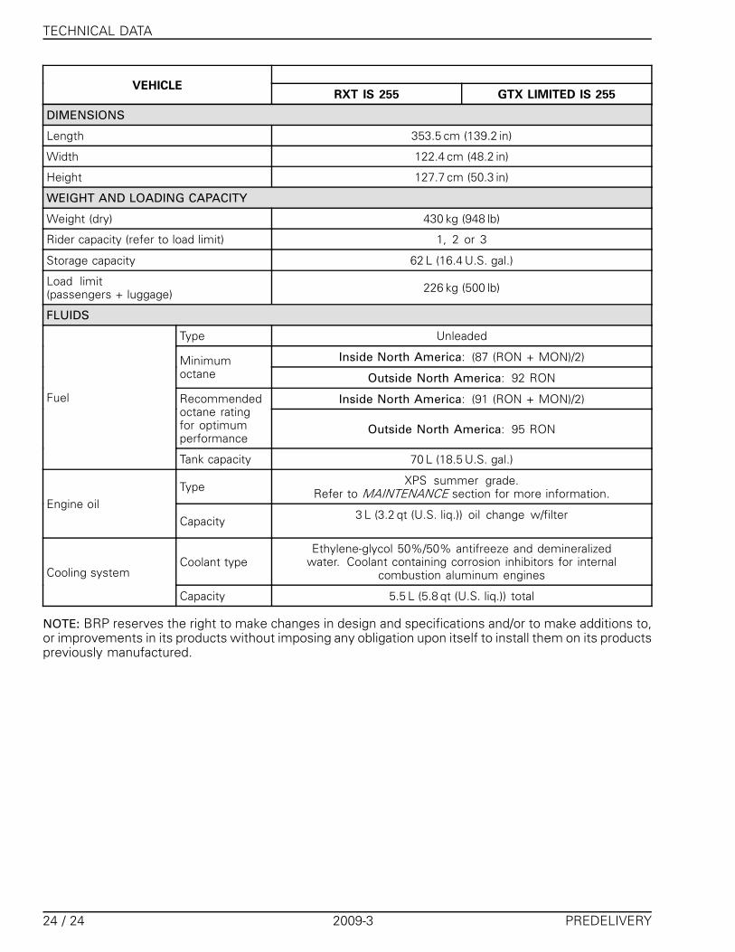
VEHICLERXT IS 255 GTX LIMITED IS 255
DIMENSIONS
Length 353.5 cm (139.2 in)
Width 122.4 cm (48.2 in)
Height 127.7 cm (50.3 in)
WEIGHT AND LOADING CAPACITY
Weight (dry) 430 kg (948 lb)
Rider capacity (refer to load limit) 1, 2 or 3
Storage capacity 62 L (16.4 U.S. gal.)
Load limit(passengers + luggage) 226 kg (500 lb)
FLUIDS
Type Unleaded
Inside North America: (87 (RON + MON)/2)Minimumoctane Outside North America: 92 RON
Inside North America: (91 (RON + MON)/2)Recommendedoctane ratingfor optimumperformance
Outside North America: 95 RON
Fuel
Tank capacity 70 L (18.5 U.S. gal.)
Type XPS summer grade.Refer to MAINTENANCE section for more information.
Engine oilCapacity 3 L (3.2 qt (U.S. liq.)) oil change w/filter
Coolant typeEthylene-glycol 50%/50% antifreeze and demineralized
water. Coolant containing corrosion inhibitors for internalcombustion aluminum enginesCooling system
Capacity 5.5 L (5.8 qt (U.S. liq.)) total
NOTE: BRP reserves the right to make changes in design and specifications and/or to make additions to,or improvements in its products without imposing any obligation upon itself to install them on its productspreviously manufactured.
24 / 24 2009-3 PREDELIVERY