AppShed AppCar Setup Guide v0.8 -...
40
AppShed AppCar Setup Guide v0.8 IMPORTANT SAFETY NOTICE AVOID BATTERY SHORT CIRCUIT Keep one battery out of the holder (DISCONNECTED) until all the wiring has been completed. If the battery wires short circuit things get very hot and you could melt the battery holder and wires. If you see any smoke, or smell something burning, REMOVE ONE BATTERY immediately. MAXIMUM VOLTAGE: 9V Please note that the maximum voltage for the NodeMCU is 9V. Do not connect a larger voltage supply as it will damage the NodeMCU.
Transcript of AppShed AppCar Setup Guide v0.8 -...
AppShed AppCar Setup Guide v0.8
IMPORTANT SAFETY NOTICE
AVOID BATTERY SHORT CIRCUIT
Keep one battery out of the holder (DISCONNECTED) until all the wiring has been completed.
If the battery wires short circuit things get very hot and you could melt the battery holder and wires.
If you see any smoke, or smell something burning, REMOVE ONE BATTERY immediately.
MAXIMUM VOLTAGE: 9V
Please note that the maximum voltage for the NodeMCU is 9V. Do not connect a larger voltage
supply as it will damage the NodeMCU.

Summary The AppShed AppCar is a very simple robotic car made using a cardboard box. The AppCar can be
controlled from any smartphone or tablet (or even a computer). This is a great project for beginners
wanting to build their first robot.
The materials are very cheap and can easily be purchased online. There is no programming required,
although you will need to install some software to get it working. Once you have the basic robot
running, you can add many advanced features using programming and additional electronics.
The robot is controlled using an app created with AppShed. You can download a pre-built app here
(http://apps.appshed.com/appcario) or you can create your own using AppShed (instructions can be
found on appshed.com)
Parts List The following parts are required:
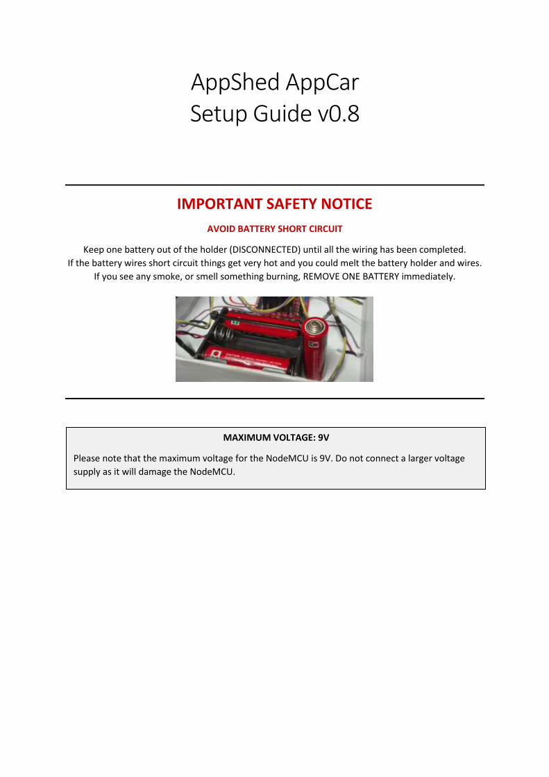
1. Controller: NodeMCU
This is an Arduino-compatible WiFi controller. It is very low cost, but
powerful, and can be used for many different projects. It can be
programmed using the Arduino software and controlled from an app.
eBay Link
2. Motors and Wheels (x2)
Many different types of motors and wheels are available. A good choice
are the low-cost geared DC motors that come with nice wheels suitable
for most small robots. (Quantity 2)
eBay Link
3. Motor Driver
A motor driver is necessary to take the signal from the controller
(NodeMCU), and “amplify” it to provide sufficient power to the motors. It
does a similar job to a music amplifier connected to big speakers.
eBay Link
4. Batteries and Battery Holder
This project can run off 4 or 6 x AA batteries, so you need a simple battery
holder with wires. 6 batteries will make it go faster but don’t go higher
otherwise you might damage the electronic components. The compact
3x2 holder gives you more space in the box.
eBay Link (Holder)
eBay Link (Batteries)
5. Jumper Wires
You need special wires to connect everything together – we call them
“jumpers”. They come with special connectors on the ends to plug into the
electronics. You will need some Male-To-Female jumpers, and some
Female-To-Female jumpers, and you might as well get some Male-To-Male
jumpers too (10 of each is sufficient).
eBay Link (M-F)
eBay Link (M-M)
eBay Link (F-F)
6. Terminal Blocks
Some of the wires will need to be joined together, and a spring-loaded
terminal block is the easiest way to do that. Simply press down and insert
the wire to connect.
eBay Link
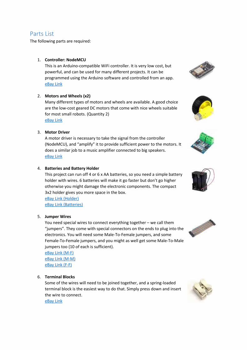
7. Swivel Wheel
Apart from the two motorised wheels, you need one (or two) swivel castor
wheels. The smaller and lighter the better (go for plastic rather than
metal).
eBay Link
8. Carboard Box
The easiest way to build your robot is to use a cardboard box! The small
boxes typically used for posting gifts are the perfect size. Recommended
size is about 8” x 6” x 2.5” (although this really doesn’t need to be
precise).
eBay Link
9. Cable Ties
Cable ties are perfect for holding things together. Quick, cheap, and no
tools required. Choose a small size, e.g. 2.5mm x 160mm. (Quantity 20)
eBay Link
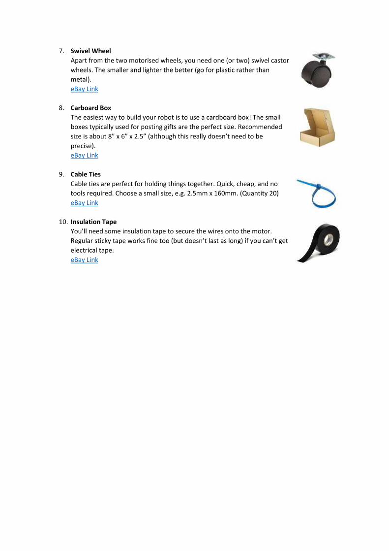
10. Insulation Tape
You’ll need some insulation tape to secure the wires onto the motor.
Regular sticky tape works fine too (but doesn’t last as long) if you can’t get
electrical tape.
eBay Link
Tools and Accessories The following items will be needed for constructing and controlling the robot:
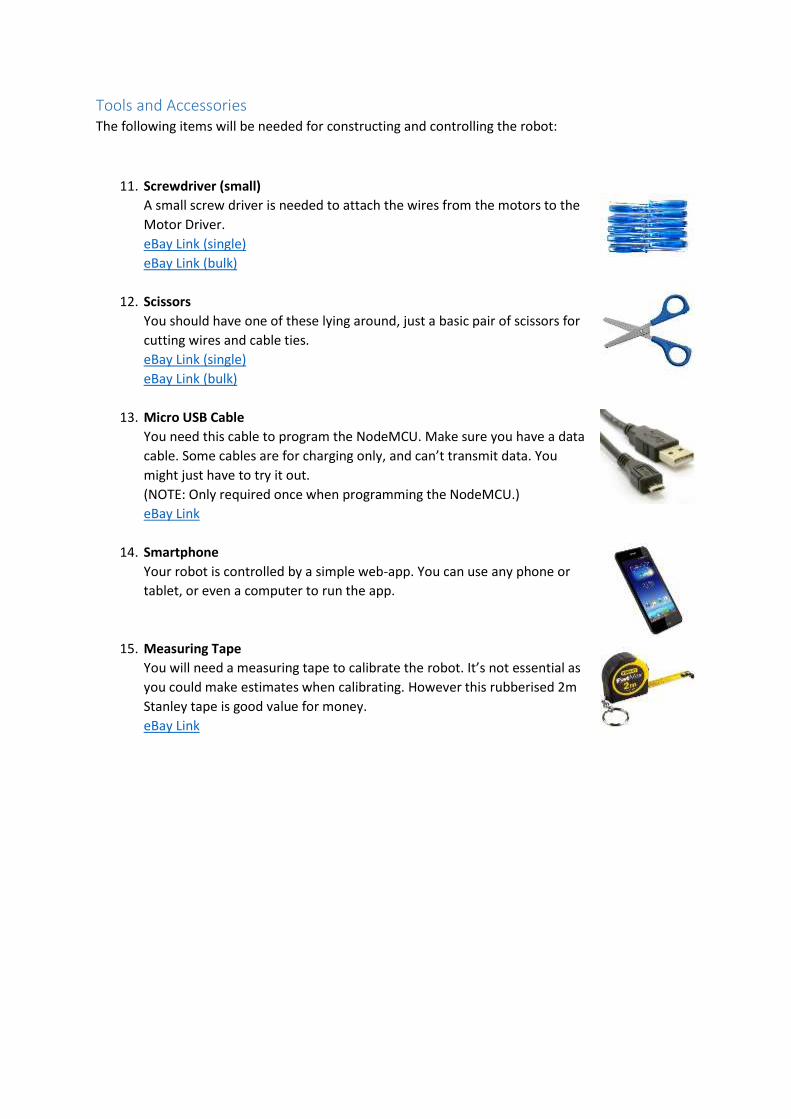
11. Screwdriver (small)
A small screw driver is needed to attach the wires from the motors to the
Motor Driver.
eBay Link (single)
eBay Link (bulk)
12. Scissors
You should have one of these lying around, just a basic pair of scissors for
cutting wires and cable ties.
eBay Link (single)
eBay Link (bulk)
13. Micro USB Cable
You need this cable to program the NodeMCU. Make sure you have a data
cable. Some cables are for charging only, and can’t transmit data. You
might just have to try it out.
(NOTE: Only required once when programming the NodeMCU.)
eBay Link
14. Smartphone
Your robot is controlled by a simple web-app. You can use any phone or
tablet, or even a computer to run the app.
15. Measuring Tape
You will need a measuring tape to calibrate the robot. It’s not essential as
you could make estimates when calibrating. However this rubberised 2m
Stanley tape is good value for money.
eBay Link
Optional Items The following items are not necessary, but can be helpful, especially if you are building robots as
part of a large group (schools, clubs etc). We include some suggestions for teachers/group leaders
running larger group sessions.
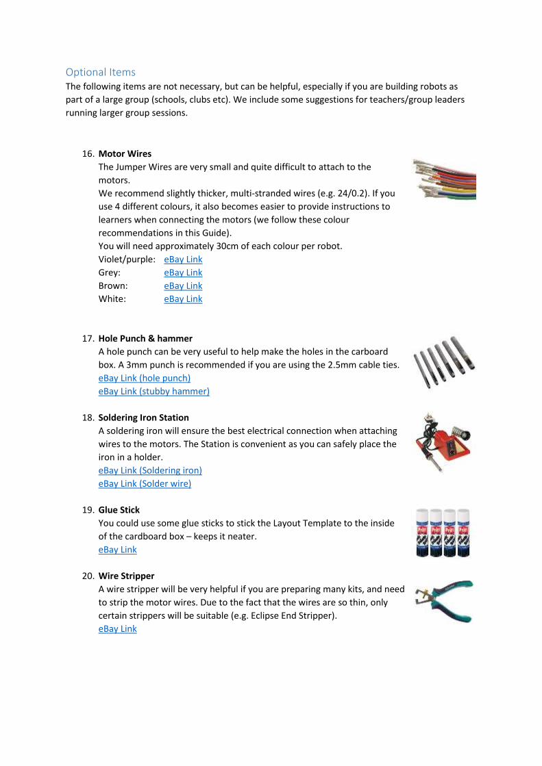
16. Motor Wires
The Jumper Wires are very small and quite difficult to attach to the
motors.
We recommend slightly thicker, multi-stranded wires (e.g. 24/0.2). If you
use 4 different colours, it also becomes easier to provide instructions to
learners when connecting the motors (we follow these colour
recommendations in this Guide).
You will need approximately 30cm of each colour per robot.
Violet/purple: eBay Link
Grey: eBay Link
Brown: eBay Link
White: eBay Link
17. Hole Punch & hammer
A hole punch can be very useful to help make the holes in the carboard
box. A 3mm punch is recommended if you are using the 2.5mm cable ties.
eBay Link (hole punch)
eBay Link (stubby hammer)
18. Soldering Iron Station
A soldering iron will ensure the best electrical connection when attaching
wires to the motors. The Station is convenient as you can safely place the
iron in a holder.
eBay Link (Soldering iron)
eBay Link (Solder wire)
19. Glue Stick
You could use some glue sticks to stick the Layout Template to the inside
of the cardboard box – keeps it neater.
eBay Link
20. Wire Stripper
A wire stripper will be very helpful if you are preparing many kits, and need
to strip the motor wires. Due to the fact that the wires are so thin, only
certain strippers will be suitable (e.g. Eclipse End Stripper).
eBay Link
Step 1: Installing the software
Duration: 30 mins
Requirements:
• Windows PC with internet access
• NodeMCU
• Micro USB cable
• Smartphone
The NodeMCU is your controller. You need to install a program onto the NodeMCU that will
communicate with your AppShed app. This program is called an Arduino Sketch.
1. Install the Arduino IDE on your computer
2. Transfer the Sketch (program) to the NodeMCU
3. Test it using your smartphone.
1. Install the Arduino IDE on your computer
1.1. Download and install the Arduino IDE (Integrated Development Environment) from:
https://www.arduino.cc/en/Main/Software
(TIP: Make sure you get the software from arduino.cc NOT arduino.org because arduino.org
does not support all the features you need.)
(TIP: On Windows it is best to “Run as Administrator”.)

1.2. Install Libraries
Libraries are extra software packs that your Arduino sketch needs to run properly.
1.2.1. In the Arduino IDE, on the main menu, select:
Sketch -> Include Library -> Manage Libraries…
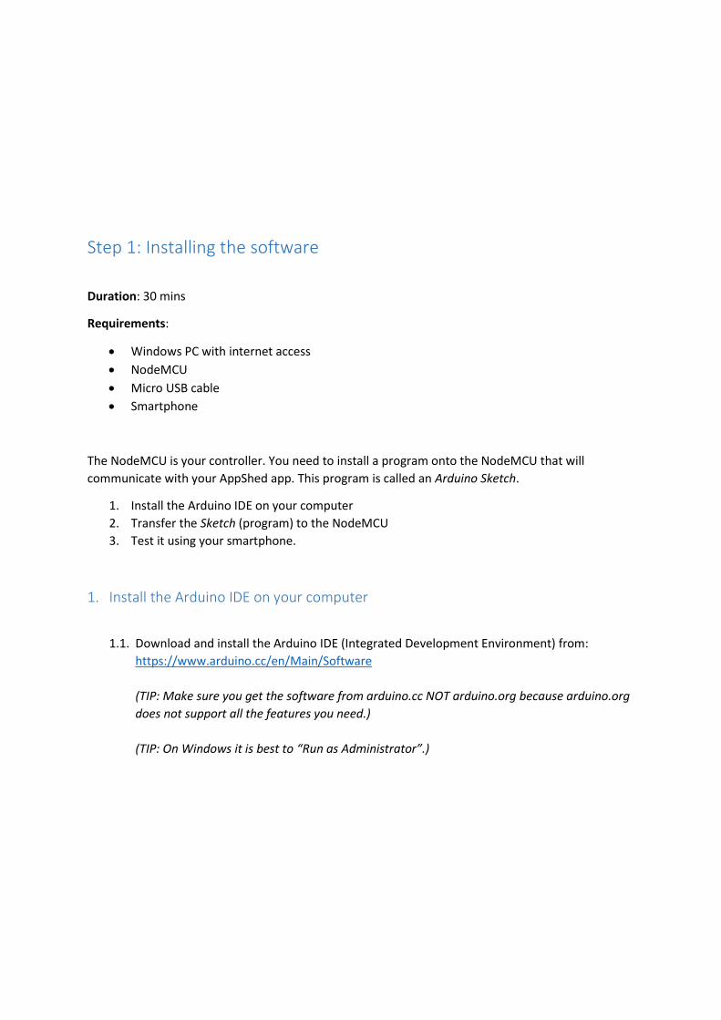
1.2.2. Search for the library called “PubSub” and install it.
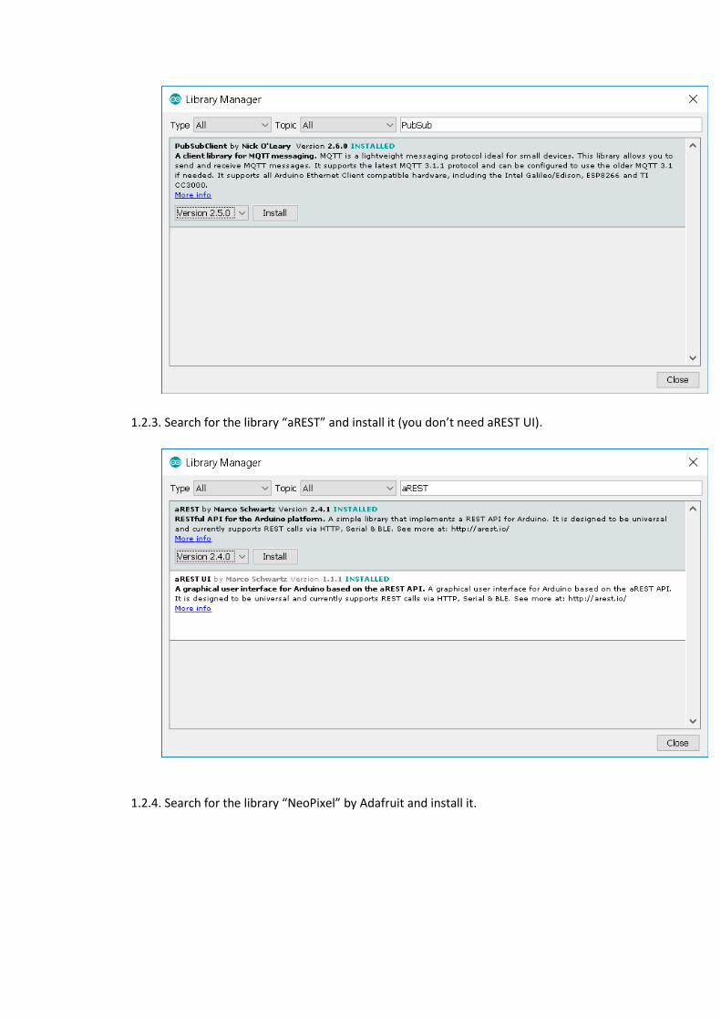
1.2.3. Search for the library “aREST” and install it (you don’t need aREST UI).
1.2.4. Search for the library “NeoPixel” by Adafruit and install it.
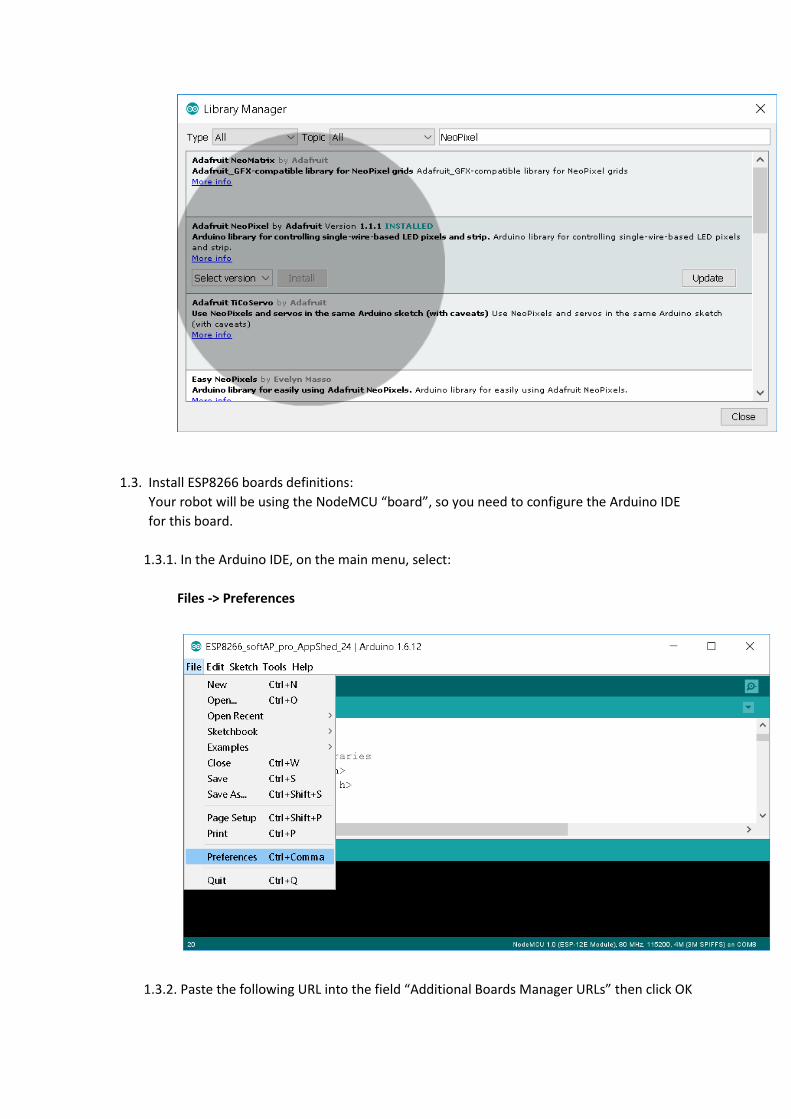
1.3. Install ESP8266 boards definitions:
Your robot will be using the NodeMCU “board”, so you need to configure the Arduino IDE
for this board.
1.3.1. In the Arduino IDE, on the main menu, select:
Files -> Preferences
1.3.2. Paste the following URL into the field “Additional Boards Manager URLs” then click OK
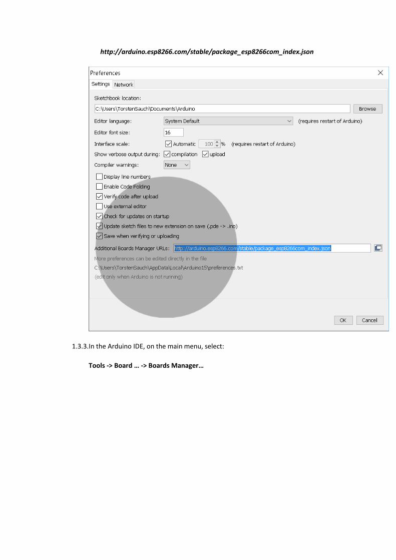
http://arduino.esp8266.com/stable/package_esp8266com_index.json
1.3.3. In the Arduino IDE, on the main menu, select:
Tools -> Board … -> Boards Manager…

1.3.4. Search for the board “esp8266” and install it.
1.3.5. Select the NodeMCU 12-E board
Tools -> Board -> NodeMCU 1.0 (ESP-12E Module)
(TIP: If you have a different version of the NodeMCU, or you are using a different
Arduino board, select that board here.)

2. Transfer the Sketch (program) to the NodeMCU
The controller (NodeMCU) needs to have a special AppShed program installed on it (also called an
Arduino “sketch”). This sketch allows the controller to communicate with the AppShed app.
2.1. Save the sketch on your computer
2.1.1. Open the sketch in a browser by clicking this link:
https://raw.githubusercontent.com/AppShed/aREST-
ESP8266_cloud_pro_AppShed/master/ESP8266_cloud_pro_AppShed
2.1.2. Right click and choose “Save as…”
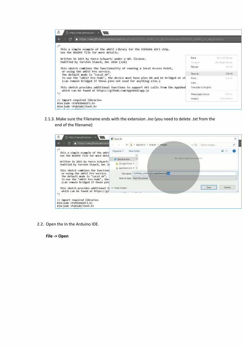
2.1.3. Make sure the Filename ends with the extension .ino (you need to delete .txt from the
end of the filename)
2.2. Open the In the Arduino IDE.
File -> Open
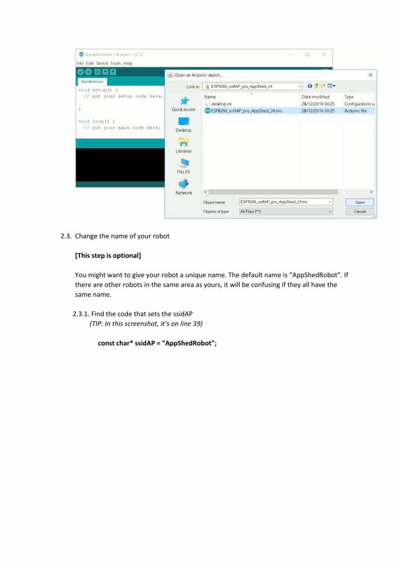
2.3. Change the name of your robot
[This step is optional]
You might want to give your robot a unique name. The default name is “AppShedRobot”. If
there are other robots in the same area as yours, it will be confusing if they all have the
same name.
2.3.1. Find the code that sets the ssidAP
(TIP: In this screenshot, it’s on line 39)
const char* ssidAP = "AppShedRobot";
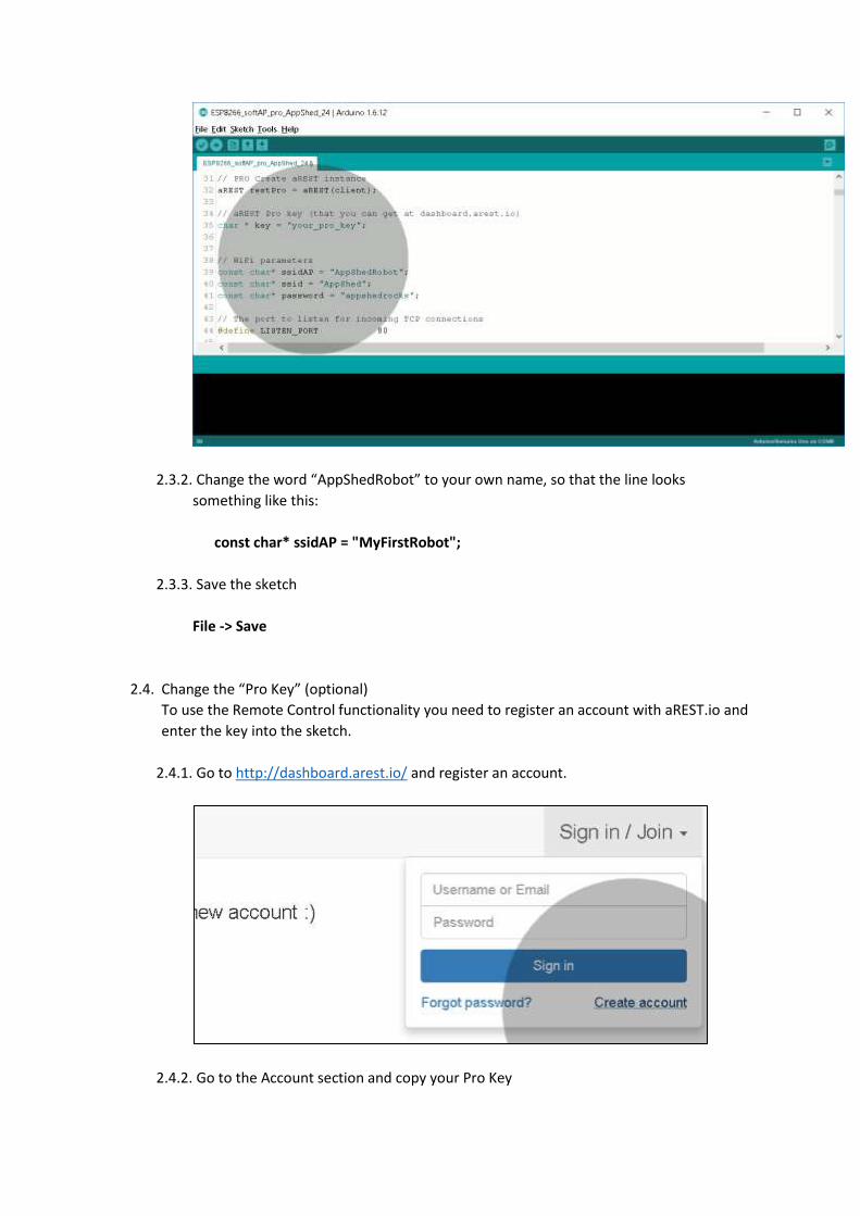
2.3.2. Change the word “AppShedRobot” to your own name, so that the line looks
something like this:
const char* ssidAP = "MyFirstRobot";
2.3.3. Save the sketch
File -> Save
2.4. Change the “Pro Key” (optional)
To use the Remote Control functionality you need to register an account with aREST.io and
enter the key into the sketch.
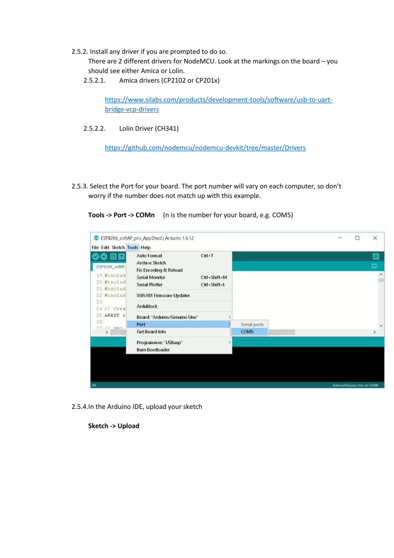
2.4.1. Go to http://dashboard.arest.io/ and register an account.
2.4.2. Go to the Account section and copy your Pro Key

2.4.3. Paste the Pro Key into the Arduino sketch where it says “your_pro_key”
2.4.4. Sav the sketch
2.5. Upload your sketch to the board
You are now ready to upload the sketch to the NodeMCU board.
2.5.1. Attach the NodeMCU to your computer using a Micro USB cable.
2.5.2. Install any driver if you are prompted to do so.
There are 2 different drivers for NodeMCU. Look at the markings on the board – you
should see either Amica or Lolin.
2.5.2.1. Amica drivers (CP2102 or CP201x)
https://www.silabs.com/products/development-tools/software/usb-to-uart-
bridge-vcp-drivers
2.5.2.2. Lolin Driver (CH341)
https://github.com/nodemcu/nodemcu-devkit/tree/master/Drivers
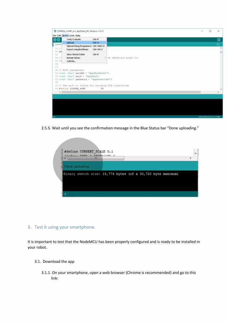
2.5.3. Select the Port for your board. The port number will vary on each computer, so don’t
worry if the number does not match up with this example.
Tools -> Port -> COMn (n is the number for your board, e.g. COM5)
2.5.4. In the Arduino IDE, upload your sketch
Sketch -> Upload
2.5.5. Wait until you see the confirmation message in the Blue Status bar “Done uploading.”
3. Test it using your smartphone.
It is important to test that the NodeMCU has been properly configured and is ready to be installed in
your robot.
3.1. Download the app
3.1.1. On your smartphone, open a web browser (Chrome is recommended) and go to this
link:

http://apps.appshed.com/appcario/
3.1.2. Follow all the screen prompts (for example, click OK when asked to download
updates, click OK to confirm that the app is available offline.)
3.1.3. Once the app has loaded in the browser, you can “Add to homescreen” to pin the icon
on your home screen.
3.2. Connect to the NodeMCU WiFi
You connect your phone to the NodeMCU over WiFi. The NodeMCU creates it’s own Access
Point (similar to a Hotspot).
3.2.1. Make sure the NodeMCU is connected to the computer via the USB cable.
3.2.2. Press and hold the Reset Button (RST) on the NodeMCU for 2 seconds, then release.
This ensures it starts up correctly.
3.2.3. On your phone (or tablet, or computer) open your WiFi settings and connect to the
WiFi Network called “AppShedRobot”.
The default password is “appshedrocks” (unless you changed it in the sketch).
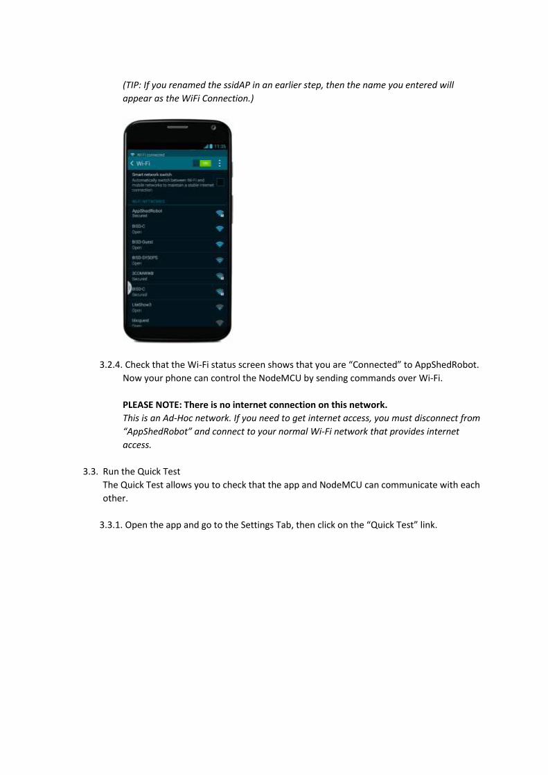
(TIP: If you renamed the ssidAP in an earlier step, then the name you entered will
appear as the WiFi Connection.)
3.2.4. Check that the Wi-Fi status screen shows that you are “Connected” to AppShedRobot.
Now your phone can control the NodeMCU by sending commands over Wi-Fi.
PLEASE NOTE: There is no internet connection on this network.
This is an Ad-Hoc network. If you need to get internet access, you must disconnect from
“AppShedRobot” and connect to your normal Wi-Fi network that provides internet
access.
3.3. Run the Quick Test
The Quick Test allows you to check that the app and NodeMCU can communicate with each
other.
3.3.1. Open the app and go to the Settings Tab, then click on the “Quick Test” link.
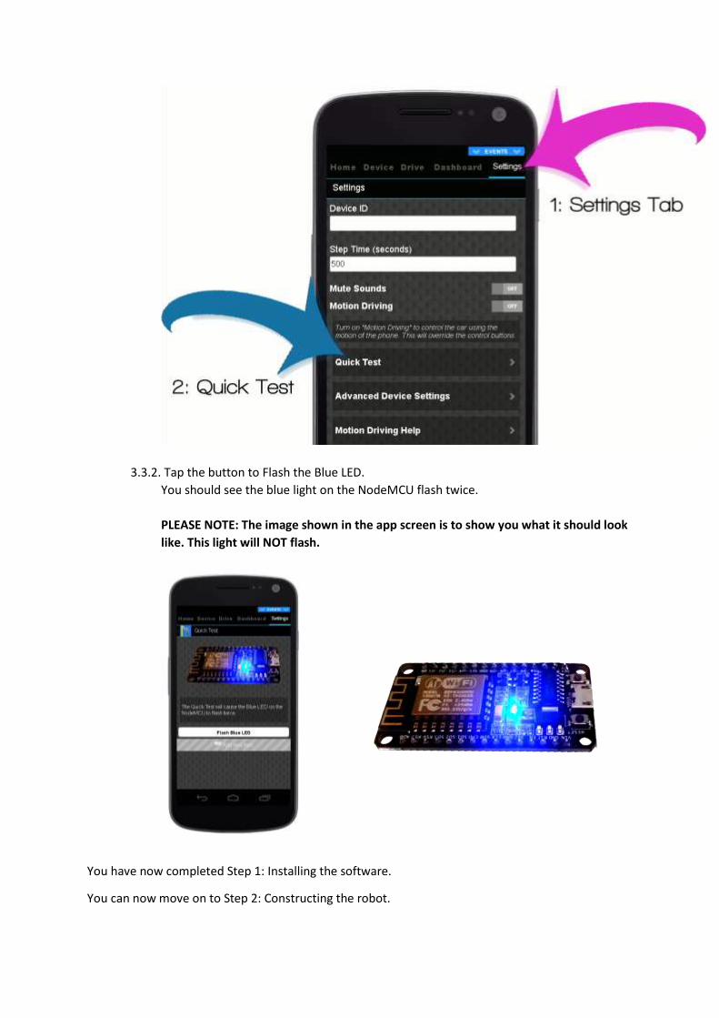
3.3.2. Tap the button to Flash the Blue LED.
You should see the blue light on the NodeMCU flash twice.
PLEASE NOTE: The image shown in the app screen is to show you what it should look
like. This light will NOT flash.
You have now completed Step 1: Installing the software.
You can now move on to Step 2: Constructing the robot.


Step 2: Constructing the robot
Duration: 15 minutes
Requirements:
• Cardboard Box
• Motors and Wheels
• NodeMCU
• Motor Driver
• Battery Holder and Batteries
• Jumper Wires (M-F)
• Swivel Wheel
• Scissors
• Cable Ties
• Insulation Tape
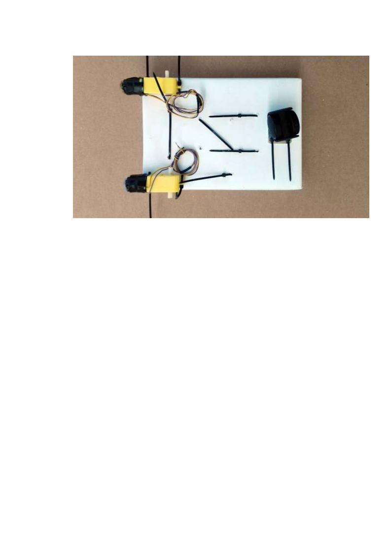
The AppShed AppCar is built using very cheap and easy-to-find parts. In this guide we use a carboard
box – the wheels are tied to the bottom and the electronics go inside. Simple and effective.
(TIP: Let your imagination run wild and build your own AppCar using any materials you like. For
example, try converting an old broken toy car to Smartphone-controlled AppCar!)
1. Connect wires to the motors
2. Put the “Layout Template” in the box
3. Tie the parts to the box
1. Connect wires to the motors
If your motors don’t have wires attached, you will need to connect two wires to the terminals on the
motor. You must make sure there is a good electrical connection so that the robot runs reliably.
1.1. Locate the terminals on the motor
The terminals are small copper “tabs” with a hole through the middle.
(TIP: If you have bought a different type of motor the terminals may look different to those
shown here.)
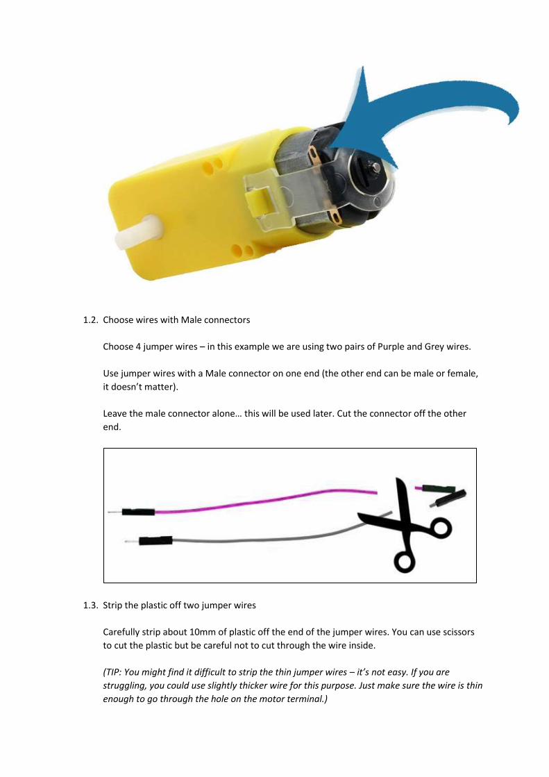
1.2. Choose wires with Male connectors
Choose 4 jumper wires – in this example we are using two pairs of Purple and Grey wires.
Use jumper wires with a Male connector on one end (the other end can be male or female,
it doesn’t matter).
Leave the male connector alone… this will be used later. Cut the connector off the other
end.
1.3. Strip the plastic off two jumper wires
Carefully strip about 10mm of plastic off the end of the jumper wires. You can use scissors
to cut the plastic but be careful not to cut through the wire inside.
(TIP: You might find it difficult to strip the thin jumper wires – it’s not easy. If you are
struggling, you could use slightly thicker wire for this purpose. Just make sure the wire is thin
enough to go through the hole on the motor terminal.)
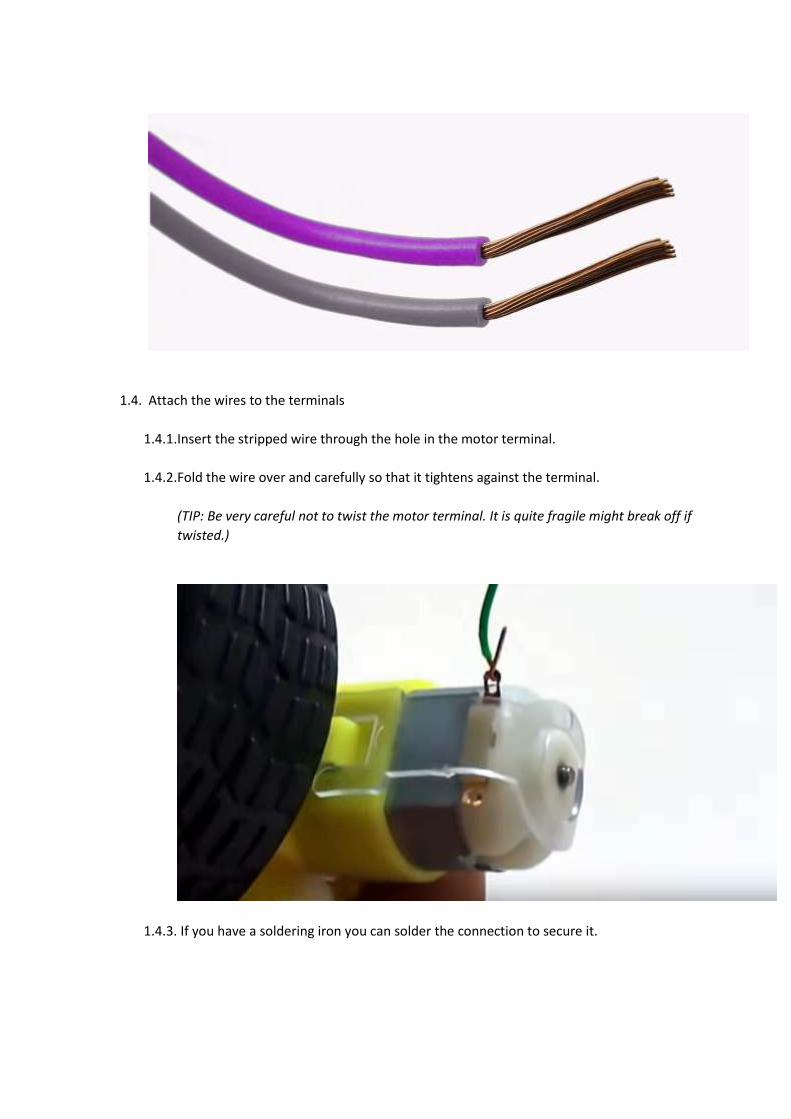
1.4. Attach the wires to the terminals
1.4.1. Insert the stripped wire through the hole in the motor terminal.
1.4.2. Fold the wire over and carefully so that it tightens against the terminal.
(TIP: Be very careful not to twist the motor terminal. It is quite fragile might break off if
twisted.)
1.4.3. If you have a soldering iron you can solder the connection to secure it.
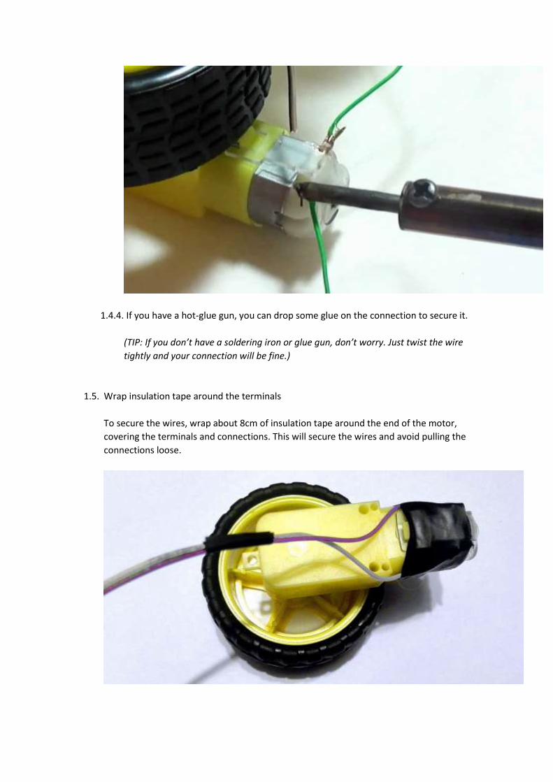
1.4.4. If you have a hot-glue gun, you can drop some glue on the connection to secure it.
(TIP: If you don’t have a soldering iron or glue gun, don’t worry. Just twist the wire
tightly and your connection will be fine.)
1.5. Wrap insulation tape around the terminals
To secure the wires, wrap about 8cm of insulation tape around the end of the motor,
covering the terminals and connections. This will secure the wires and avoid pulling the
connections loose.
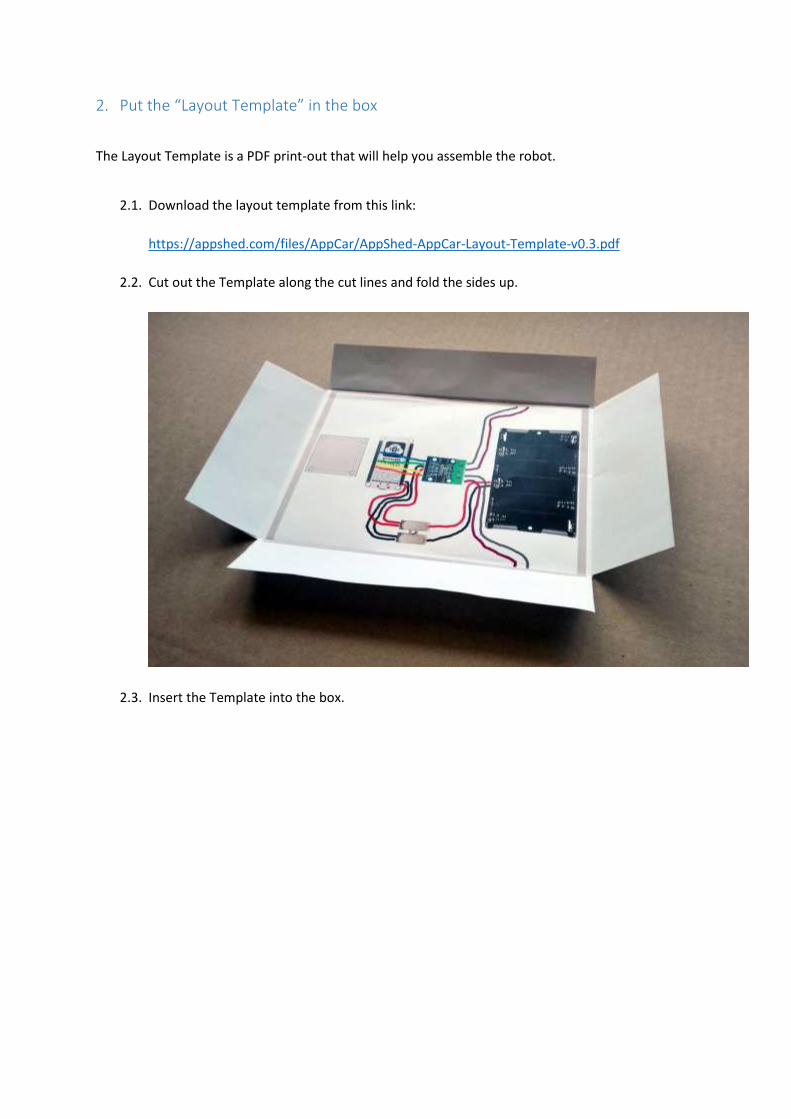
2. Put the “Layout Template” in the box
The Layout Template is a PDF print-out that will help you assemble the robot.
2.1. Download the layout template from this link:
https://appshed.com/files/AppCar/AppShed-AppCar-Layout-Template-v0.3.pdf
2.2. Cut out the Template along the cut lines and fold the sides up.
2.3. Insert the Template into the box.
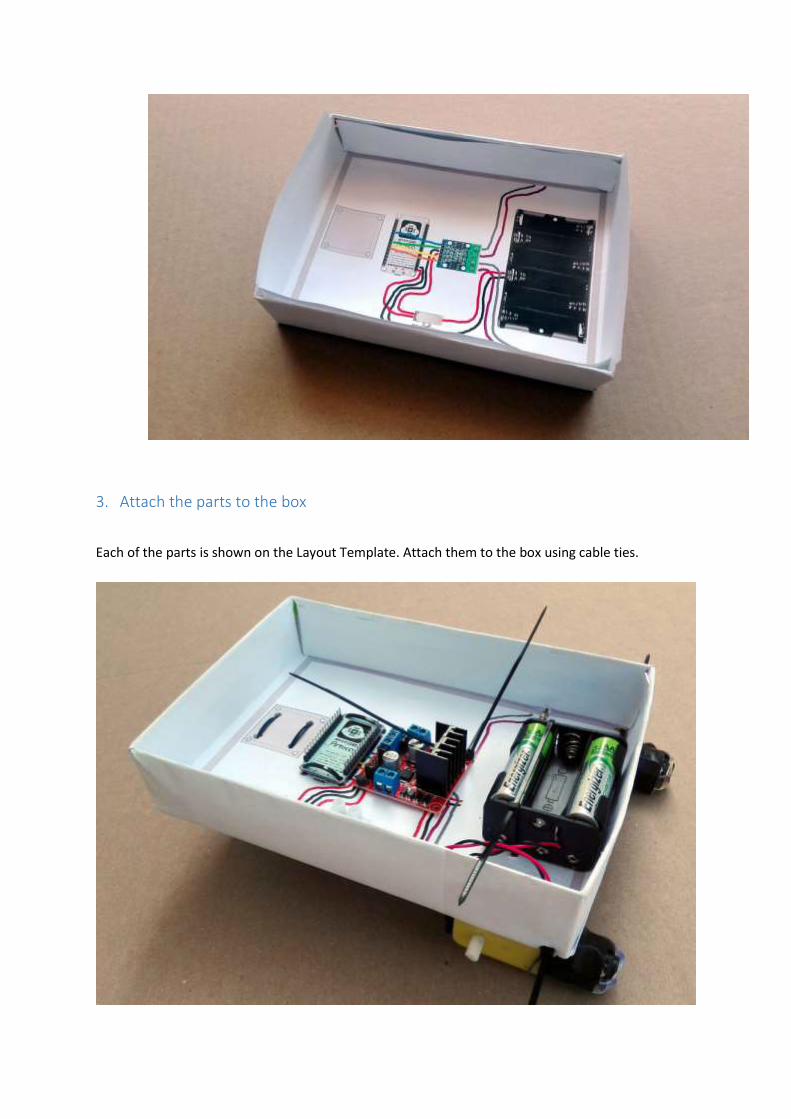
3. Attach the parts to the box
Each of the parts is shown on the Layout Template. Attach them to the box using cable ties.
3.1. Attach the NodeMCU
3.1.1. Find the image of the NodeMCU on the Layout Template.
3.1.2. Using a screwdriver of scissors, make four holes at the four corners, as shown in the
image.
3.1.3. Push cable ties through the holes and tie down the board.
3.2. Attach the Motor Driver to the box.
(Follow the same procedure as the NodeMCU.)
3.3. Attach the Terminal Block to the box.
(Follow the same procedure as the previous parts.)
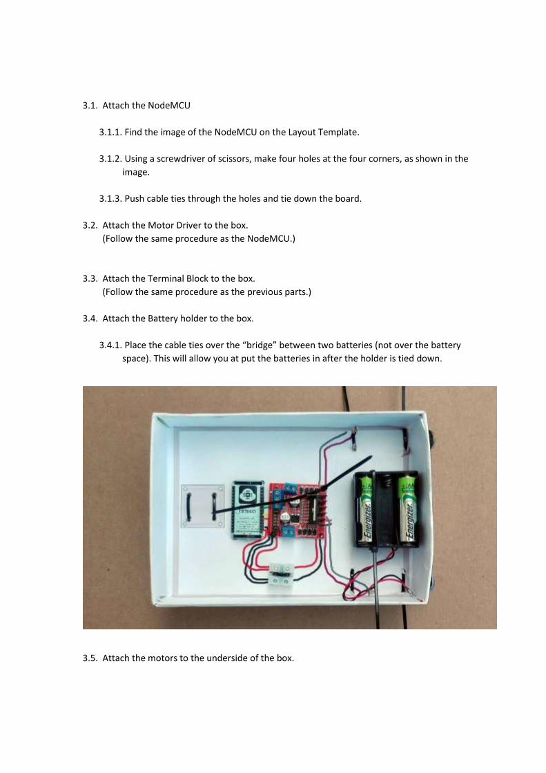
3.4. Attach the Battery holder to the box.
3.4.1. Place the cable ties over the “bridge” between two batteries (not over the battery
space). This will allow you at put the batteries in after the holder is tied down.
3.5. Attach the motors to the underside of the box.
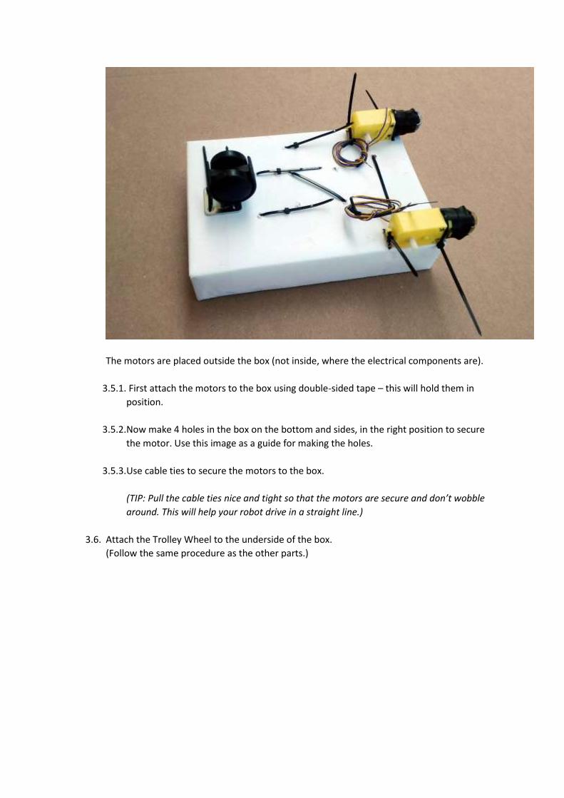
The motors are placed outside the box (not inside, where the electrical components are).
3.5.1. First attach the motors to the box using double-sided tape – this will hold them in
position.
3.5.2. Now make 4 holes in the box on the bottom and sides, in the right position to secure
the motor. Use this image as a guide for making the holes.
3.5.3. Use cable ties to secure the motors to the box.
(TIP: Pull the cable ties nice and tight so that the motors are secure and don’t wobble
around. This will help your robot drive in a straight line.)
3.6. Attach the Trolley Wheel to the underside of the box.
(Follow the same procedure as the other parts.)
Step 3: Connecting the electronics
Duration: 5 minutes
Requirements:
• Jumper Wires (F-F)
• Terminal Blocks
• Screwdriver
Connect all the components together using the various wires. Follow the printed Layout Guide to
connect them correctly.
1. Motor Shield
The Motor Shield is the preferred choice when using the AppCar. The NodeMCU chip fits into
headers on the shield, meaning that no jumper wires are required to connect these two
components. The shield also has header pins for all other I/O pins which makes it easier to add
additional sensors to your project.
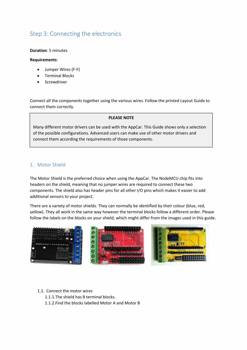
There are a variety of motor shields. They can normally be identified by their colour (blue, red,
yellow). They all work in the same way however the terminal blocks follow a different order. Please
follow the labels on the blocks on your shield, which might differ from the images used in this guide.
1.1. Connect the motor wires
1.1.1. The shield has 8 terminal blocks.
1.1.2. Find the blocks labelled Motor A and Motor B
PLEASE NOTE
Many different motor drivers can be used with the AppCar. This Guide shows only a selection
of the possible configurations. Advanced users can make use of other motor drivers and
connect them according the requirements of those components.
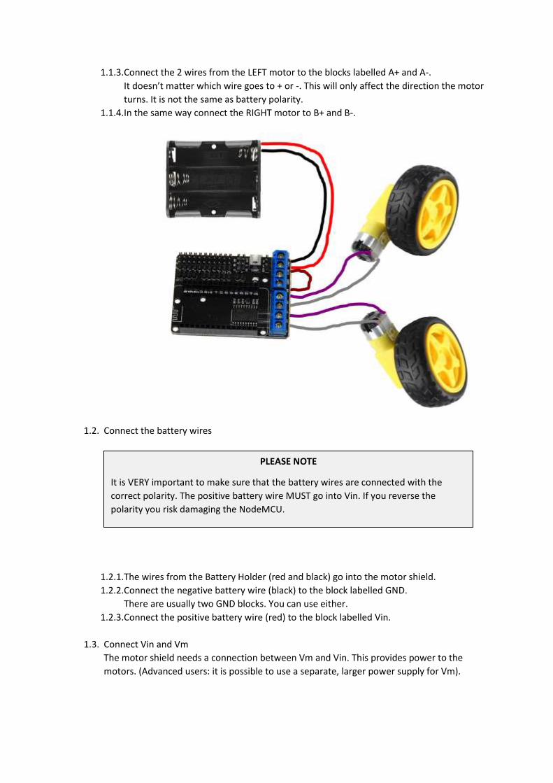
1.1.3. Connect the 2 wires from the LEFT motor to the blocks labelled A+ and A-.
It doesn’t matter which wire goes to + or -. This will only affect the direction the motor
turns. It is not the same as battery polarity.
1.1.4. In the same way connect the RIGHT motor to B+ and B-.
1.2. Connect the battery wires
1.2.1. The wires from the Battery Holder (red and black) go into the motor shield.
1.2.2. Connect the negative battery wire (black) to the block labelled GND.
There are usually two GND blocks. You can use either.
1.2.3. Connect the positive battery wire (red) to the block labelled Vin.
1.3. Connect Vin and Vm
The motor shield needs a connection between Vm and Vin. This provides power to the
motors. (Advanced users: it is possible to use a separate, larger power supply for Vm).
PLEASE NOTE
It is VERY important to make sure that the battery wires are connected with the
correct polarity. The positive battery wire MUST go into Vin. If you reverse the
polarity you risk damaging the NodeMCU.
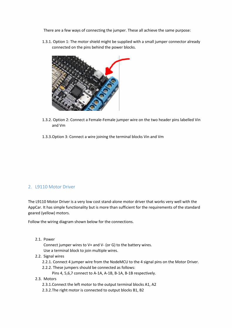
There are a few ways of connecting the jumper. These all achieve the same purpose:
1.3.1. Option 1: The motor shield might be supplied with a small jumper connector already
connected on the pins behind the power blocks.
1.3.2. Option 2: Connect a Female-Female jumper wire on the two header pins labelled Vin
and Vm
1.3.3. Option 3: Connect a wire joining the terminal blocks Vin and Vm
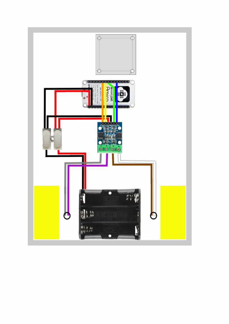
2. L9110 Motor Driver
The L9110 Motor Driver is a very low cost stand-alone motor driver that works very well with the
AppCar. It has simple functionality but is more than sufficient for the requirements of the standard
geared (yellow) motors.
Follow the wiring diagram shown below for the connections.
2.1. Power
Connect jumper wires to V+ and V- (or G) to the battery wires.
Use a terminal block to join multiple wires.
2.2. Signal wires
2.2.1. Connect 4 jumper wire from the NodeMCU to the 4 signal pins on the Motor Driver.
2.2.2. These jumpers should be connected as follows:
Pins 4, 5,6,7 connect to A-1A, A-1B, B-1A, B-1B respectively.
2.3. Motors
2.3.1. Connect the left motor to the output terminal blocks A1, A2
2.3.2. The right motor is connected to output blocks B1, B2

3. L298 Motor Driver 3.1. cvxc
The connections for this motor driver are very similar to the L9110 (above)
Step 4: Drive the robot with an app
Duration: 5 minutes
Requirements:
• Smartphone
1. Overview
2. Download the app The AppCar app is available as a web app or installed as an iPhone, iPad or Android app.
2.1. Web App
Open this link in a browser (mobile, tablet or PC)
apps.appshed.com/appcario/
2.2. Android
Find “AppCar” by AppShed in the Google Play Store
2.3. iOS
Find “AppCar” by AppShed in iTunes AppStore
3. Connect to the AppCar
Follow the instructions in this video to connect your phone to the AppCar.
(Although this video uses iPhone, the Android connection is very similar)
4. Calibrate
5. Code

Next Steps…
Driving over the internet
Writing auto-pilot programs
Creating your own app
Adding more sensors and things