
Rick Etter Airports Acquisition Specialist FAA, Office of Airport Planning and Programming

5-1
This chapter discusses general planning and conduct ofinstrument approaches by professional pilots operatingunder Title 14 of the Code of Federal Regulations (14CFR) Parts 91, 121, 125, and 135. Operations specific tohelicopters are covered in Chapter 7. The operationsspecifications (OpsSpecs), standard operating proce-dures (SOPs), and any other Federal AviationAdministration (FAA) approved documents for eachcommercial operator are the final authorities for individ-ual authorizations and limitations as they relate to instru-ment approaches. While coverage of the variousauthorizations and approach limitations for all operatorsis beyond the scope of this chapter, an attempt is madeto give examples from generic manuals where it isappropriate.
APPROACH PLANNINGDepending on speed of the aircraft, availability ofweather information, and the complexity of theapproach procedure or special terrain avoidanceprocedures for the airport of intended landing, theinflight planning phase of an instrument approachcan begin as far as 100-200 NM from the destina-tion. Some of the approach planning should beaccomplished during preflight. In general, there arefive steps that most operators incorporate into theirFlight Standards manuals for the inflight planningphase of an instrument approach:
• Gathering weather information, field conditions,and Notices to Airmen (NOTAMs) for the runwayof intended landing.
• Calculation of performance data, approach speeds,and thrust/power settings.
• Flight deck navigation/communication and automa-tion setup.
• Instrument approach procedure (IAP) review and,for flight crews, IAP briefing.
• Operational review and, for flight crews, opera-tional briefing.
Although often modified to suit each individual opera-tor, these five steps form the basic framework for theinflight-planning phase of an instrument approach. The
extent of detail that a given operator includes in theirSOPs varies from one operator to another; some maydesignate which pilot performs each of the aboveactions, the sequence, and the manner in which eachaction is performed. Others may leave much of the detailup to individual flight crews and only designate whichtasks should be performed prior to commencing anapproach. Flight crews of all levels, from single-pilot tomulti-crewmember Part 91 operators, can benefit fromthe experience of commercial operators in developingtechniques to fly standard instrument approach proce-dures (SIAPs).
Determining the suitability of a specific IAP can be avery complex task, since there are many factors that canlimit the usability of a particular approach. There areseveral questions that pilots need to answer during pre-flight planning and prior to commencing an approach. Isthe approach procedure authorized for the company, ifPart 91K, 121, 125, or 135? Is the weather appropriatefor the approach? Is the aircraft currently at a weight thatwill allow it the necessary performance for the approachand landing or go around/missed approach? Is the air-craft properly equipped for the approach? Is the flightcrew qualified and current for the approach? Many ofthese types of issues must be considered during preflightplanning and within the framework of each specific aircarrier’s OpsSpecs, or Part 91.
WEATHER CONSIDERATIONSWeather conditions at the field of intended landingdictate whether flight crews need to plan for an instru-ment approach and, in many cases, determine whichapproaches can be used, or if an approach can even beattempted. The gathering of weather informationshould be one of the first steps taken during theapproach-planning phase. Although there are manypossible types of weather information, the primaryconcerns for approach decision-making are windspeed, wind direction, ceiling, visibility, altimetersetting, temperature, and field conditions. It is also agood idea to check NOTAMs at this time in casethere were any changes since preflight planning.
Wind speed and direction are factors because theyoften limit the type of approach that can be flown at

5-2
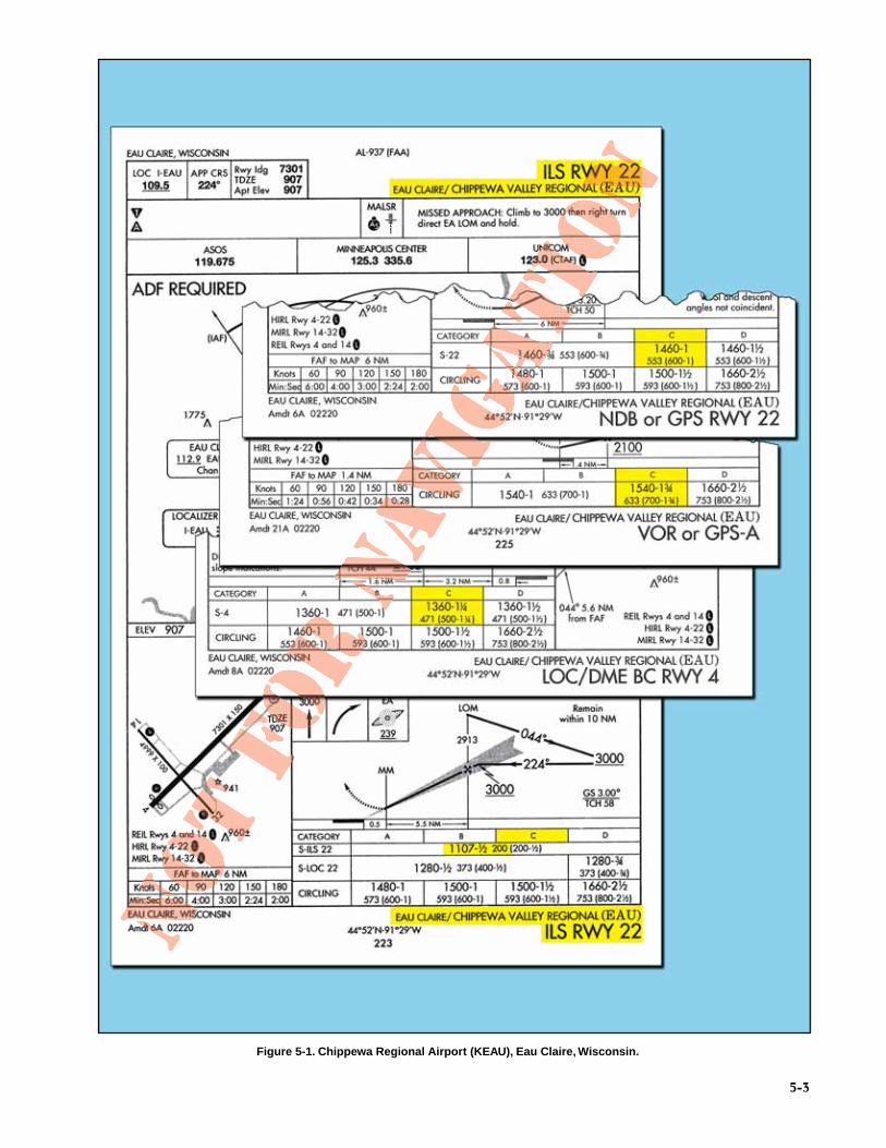
a specific location. This typically is not a factor atairports with multiple precision approaches, but atairports with only a few or one approach procedurethe wrong combination of wind and visibility canmake all instrument approaches at an airportunavailable. As an example, consider the availableapproaches at the Chippewa Valley RegionalAirport (KEAU) in Eau Claire, Wisconsin, shownin Figure 5-1. In the event that the visibility isreported as less than one mile, the only useableapproach for Category C airplanes is the InstrumentLanding System (ILS) to Runway 22. This leavesvery few options for flight crews if the wind doesnot favor Runway 22; and, in cases where the windrestricts a landing on that runway altogether, even acircling approach cannot be flown because of thevisibility.
WEATHER SOURCESMost of the weather information that flight crewsreceive is issued to them prior to the start of each flightsegment, but the weather used for inflight planning andexecution of an instrument approach is normallyobtained en route via government sources, companyfrequency, or Aircraft Communications Addressing andReporting System (ACARS).
Air carriers and operators certificated under theprovisions of Part 119 (Certification: Air Carriersand Commercial Operators) are required to use theaeronautical weather information systems definedin the OpsSpecs issued to that certificate holder bythe FAA. These systems may use basic FAA/NationalWeather Service (NWS) weather services, contractoror operator-proprietary weather services and/orEnhanced Weather Information System (EWINS)when approved in the OpsSpecs. As an integral partof EWINS approval, the procedures for collecting,producing, and disseminating aeronautical weatherinformation, as well as the crewmember and dis-patcher training to support the use of systemweather products, must be accepted or approved.
Operators not certificated under the provisions of Part119 are encouraged to use FAA/NWS products throughAutomated Flight Service Stations (AFSSs), DirectUser Access Terminal System (DUATS), and/or FlightInformation Services Data Link (FISDL). Refer to theAeronautical Information Manual (AIM) for moreinformation regarding AFSSs, DUATS, and FISDL.
The suite of available aviation weather product types isexpanding with the development of new sensor sys-tems, algorithms, and forecast models. The FAA andNWS, supported by the National Center forAtmospheric Research and the Forecast SystemsLaboratory, develop and implement new aviation
weather product types through a comprehensive processknown as the Aviation Weather Technology Transferprocess. This process ensures that user needs andtechnical and operational readiness requirements aremet as experimental product types mature to opera-tional application.
The development of enhanced communications capa-bilities, most notably the Internet, has allowed pilotsaccess to an ever-increasing range of weather serviceproviders and proprietary products. It is not the intentof the FAA to limit operator use of this weather infor-mation. However, pilots and operators should be awarethat weather services provided by entities other thanthe FAA, NWS, or their contractors (such as theDUATS and FISDL providers) may not meetFAA/NWS quality control standards. Therefore, opera-tors and pilots contemplating use of such servicesshould consider the following in determining the suit-ability of that service or product. In many cases, thismay be accomplished by provider disclosure or adescription of services or products:
Is the service or product applicable for aviation use?
• Does the weather product or service provideinformation that is usable in aeronautical deci-sion-making?
• Does the product or service fail to provide datanecessary to make critical aeronautical weatherdecisions?
Does the service provide data/products produced byapproved aviation weather information sources?
• Are these data or this product modified?
• If so, is the modification process described, and isthe final product in a configuration that supportsaeronautical weather decision-making?
Are the weather products professionally developed andproduced and/or quality-controlled by a qualified avia-tion meteorologist?
Does the provider’s quality assurance plan include thecapability to monitor generated products and contain aprocedure to correct deficiencies as they are discovered?
Is the product output consistent with original datasources?
Are education and training materials sufficient to enableusers to use the new product effectively?
Are the following key elements of the product intuitiveand easy for the user to interpret?
• Type of data/product.
• Currency or age of data/product.
5-3
Figure 5-1. Chippewa Regional Airport (KEAU), Eau Claire, Wisconsin.

5-4
• Method for displaying and decoding thedata/product.
• Location/mapping of the data.
Is the product suitable for use? Consider potential pilotmisunderstandings due to:
• Complexity of the product.
• Nonstandard display (colors, labels).
• Incorrect mapping/display of data.
• Incorrect overlay of weather data with other data(terrain, navigational aids (NAVAIDs), way-points, etc.).
• Inappropriate display of missing data.
• Missing or inaccurate time/date stamp onproduct.
Pilots and operators should be cautious when usingunfamiliar products, or products not supported by tech-nical specifications that satisfy the considerations notedabove.
NOTE: When in doubt, use FAA/NWS productswith the consultation of an FAA AFSS specialist.
BROADCAST WEATHERThe most common method used by flight crews toobtain specific inflight weather information is to use asource that broadcasts weather for the specific airport.Information about ceilings, visibility, wind, tempera-ture, barometric pressure, and field conditions can beobtained from most types of broadcast weatherservices. Broadcast weather can be transmitted tothe aircraft in radio voice format or digital format,if it is available, via an ACARS system.
AUTOMATIC TERMINAL INFORMATION SERVICEThe weather broadcast system found most often atairports with air traffic control towers in the NationalAirspace System (NAS) is the automatic terminalinformation service (ATIS). The AIM defines ATISas the continuous broadcast of recorded non-controlinformation in selected high activity terminal areas.The main purpose of ATIS is the reduction of fre-quency congestion and controller workload. It isbroadcast over very high frequency (VHF) radiofrequencies, and is designed to be receivable up to60 NM from the transmitter at altitudes up to 25,000feet above ground level (AGL). ATIS is typicallyderived from an automated weather observationsystem or a human weather observer’s report.
AUTOMATED WEATHER OBSERVING PROGRAMSAutomated surface observation systems can providepilots with weather information over discrete VHF fre-quencies or over the voice portion of local NAVAIDs.
The automated weather observing system (AWOS) andautomated surface observing system (ASOS) providereal-time weather information that can be used by flightcrews to make approach decisions, and by the NWS togenerate aviation routine weather reports (METARs).Flight crews planning approaches to airports whereATIS is not available may be able to obtain currentairport conditions from an AWOS/ASOS facility.
FAA-owned and operated AWOS-2 and AWOS-3systems are approved sources of weather for Part 121and 135 operations. Also, NWS-operated ASOSs areapproved sources of weather for Part 121 and 135operations. An AWOS/ASOS cannot be used as anauthorized weather source for Part 121 or 135 instru-ment flight rules (IFR) operations if the visibility oraltimeter setting is reported missing from the report.Refer to the AIM for the most current informationon automated weather observation systems.
CENTER WEATHERIn the event that an airport has weather observation capa-bility, but lacks the appropriate equipment to transmitthat information over a radio frequency, air route trafficcontrol centers (ARTCCs) can provide flight crews withhourly METAR or non-routine (special) aviationweather report (SPECI) information for those airports.For example, as an aircraft approaches an airport, thecenter controller can voluntarily or upon request providethe pilot with the most recent weather observation.Terminal Radar Approach Control (TRACON) facilitiesalso provide weather observation information on a work-load-permitting basis. Another option to obtain a currentMETAR or SPECI is to contact an En Route FlightAdvisory Service facility (Flight Watch).
REGULATORY REQUIREMENTSThere are many practical reasons for reviewing weatherinformation prior to initiating an instrument approach.Pilots must familiarize themselves with the conditionof individual airports and runways so that they maymake informed decisions regarding fuel management,diversions, and alternate planning. Because this infor-mation is critical, CFRs require pilots to comply withspecific weather minimums for planning and executionof instrument flights and approaches.
PART 91 OPERATORSAccording to Part 91.103, the pilot in command mustbecome familiar with all available information con-cerning a flight prior to departure. Included in thisdirective is the fundamental basis for pilots to reviewNOTAMs and pertinent weather reports and forecastsfor the intended route of flight. This review shouldinclude current weather reports and terminal forecastsfor all intended points of landing and alternate airports.In addition, a thorough review of an airport’s currentweather conditions should always be conducted priorto initiating an instrument approach. Pilots should also
consider weather information as a planning tool for fuelmanagement.
For flight planning purposes, weather informationmust be reviewed in order to determine the necessityand suitability of alternate airports. For Part 91 opera-tions, the 600-2 and 800-2 rule applies to airports withprecision and nonprecision approaches, respectively.Approaches with vertical guidance (APV) are consid-ered semi-precision and nonprecision since they do notmeet the International Civil Aviation Organization(ICAO) Annex 10 standards for a precision approach.(See Final Approach Segment section later in thischapter for more information regarding APVapproaches.) Exceptions to the 600-2 and 800-2 alter-nate minimums are listed in the front of the NationalAeronautical Charting Office (NACO) U.S. TerminalProcedures Publication (TPP) and are indicated by an“ ” symbol on the approach charts for the airport.This does not preclude flight crews from initiatinginstrument approaches at alternate airports when theweather conditions are below these minimums. The600-2 and 800-2 rules, or any exceptions, only apply toflight planning purposes, while published landing min-imums apply to the actual approach at the alternate.
PART 135 OPERATORSUnlike Part 91 operators, Part 135 operators may notdepart for a destination unless the forecast weatherthere will allow an instrument approach and landing.According to Part 135.219, flight crews and dispatchersmay only designate an airport as a destination if the lat-est weather reports or forecasts, or any combination ofthem, indicate that the weather conditions will be at orabove IFR landing minimums at the estimated time ofarrival (ETA). This ensures that Part 135 flight crewsconsider weather forecasts when determining thesuitability of destinations. Departures for airportscan be made when the forecast weather shows theairport will be at or above IFR minimums at theETA, even if current conditions indicate the airportto be below minimums. Conversely, Part 135.219prevents departures when the first airport of intendedlanding is currently above IFR landing minimums,but the forecast weather is below those minimums atthe ETA.
Another very important difference between Part 91and Part 135 operations is the Part 135 requirementfor airports of intended landing to meet specificweather criteria once the flight has been initiated. ForPart 135, not only is the weather required to be fore-cast at or above IFR landing minimums for planning adeparture, but it also must be above minimums for ini-tiation of an instrument approach and, once theapproach is initiated, to begin the final approach seg-ment of an approach. Part 135.225 states that pilotsmay not begin an instrument approach unless the
5-5
latest weather report indicates that the weather con-ditions are at or above the authorized IFR landingminimums for that procedure. Part 135.225 pro-vides relief from this rule if the aircraft has alreadypassed the FAF when the weather report is received.It should be noted that the controlling factor fordetermining whether or not the aircraft can proceedis reported visibility. Runway visual range (RVR),if available, is the controlling visibility report fordetermining that the requirements of this sectionare met. The runway visibility value (RVV),reported in statute miles (SM), takes precedent overprevailing visibility. There is no required timeframefor receiving current weather prior to initiating theapproach.
PART 121 OPERATORSLike Part 135 operators, flight crews and dispatchersoperating under Part 121 must ensure that the appropri-ate weather reports or forecasts, or any combinationthereof, indicate that the weather will be at or above theauthorized minimums at the ETA at the airport to whichthe flight is dispatched (Part 121.613). This regulationattempts to ensure that flight crews will always be ableto execute an instrument approach at the destinationairport. Of course, weather forecasts are occasionallyinaccurate; therefore, a thorough review of currentweather is required prior to conducting an approach.Like Part 135 operators, Part 121 operators arerestricted from proceeding past the FAF of aninstrument approach unless the appropriate IFRlanding minimums exist for the procedure. In addi-tion, descent below the minimum descent altitude(MDA), decision altitude (DA), or decision height(DH) is governed, with one exception, by the samerules that apply to Part 91 operators. The exception isthat during Part 121 and 135 operations, the airplaneis also required to land within the touchdown zone(TDZ). Refer to the section titled Minimum DescentAltitude, Decision Altitude, and Decision Height laterin this chapter for more information regarding MDA,DA, and DH.
PERFORMANCE CONSIDERATIONSAll operators are required to comply with specificairplane performance limitations that governapproach and landing. Many of these requirementsmust be considered prior to the origination of flight.The primary goal of these performance considerationsis to ensure that the aircraft can remain clear of obstruc-tions throughout the approach, landing, and go-aroundphase of flight, as well as land within the distancerequired by the FAA. Although the majority of in-depthperformance planning for an instrument flight is nor-mally done prior to the aircraft’s departure, a generalreview of performance considerations is usuallyconducted prior to commencing an instrumentapproach.

5-6
AIRPLANE PERFORMANCE OPERATINGLIMITATIONSGenerally speaking, air carriers must have in placean approved method of complying with Subpart I ofParts 121 and 135 (Airplane Performance OperatingLimitations), thereby proving the airplane’s per-formance capability for every flight that it intendsto make. Flight crews must have an approvedmethod of complying with the approach and landingperformance criteria in the applicable regulationsprior to departing for their intended destination.The primary source of information for performancecalculations for all operators, including Part 91, is theapproved Aircraft Flight Manual (AFM) or Pilot’sOperating Handbook (POH) for the make and modelof aircraft that is being operated. It is required tocontain the manufacturer determined performancecapabilities of the aircraft at each weight, altitude,and ambient temperature that are within the air-plane’s listed limitations. Typically, the AFMfor a large turbine powered airplane should containinformation that allows flight crews to determinethat the airplane will be capable of performingthe following actions, considering the airplane’slanding weight and other pertinent environmentalfactors:
• Land within the distance required by the regula-tions.
• Climb from the missed approach point (MAP)and maintain a specified climb gradient with oneengine inoperative.
• Perform a go-around from the final stage oflanding and maintain a specified climb gradi-ent with all engines operating and the airplanein the landing configuration.
Many airplanes have more than one allowable flapconfiguration for normal landing. Often, a reducedflap setting for landing will allow the airplane tooperate at a higher landing weight into a field thathas restrictive obstacles in the missed approach orrejected landing climb path. On these occasions, thefull-flap landing speed may not allow the airplaneenough energy to successfully complete a go-aroundand avoid any high terrain that might exist on theclimb out. Therefore, all-engine and engine-outmissed approaches, as well as rejected landings,must be taken into consideration in compliance withthe regulations. [Figure 5-2]
Flaps 30° Approach
Flaps 17° Approach
Climb Performance not Adequatefor TerrainMissed approach with full landing flaps,
lowest approach speed, but poor performance in missed approach climb.
Missed approach with lower flap setting, higher approach speed, and improved climb performance.
Figure 5-2. Reduced Flap Settings Effect on Go-Around.

5-7
APPROACH SPEED AND CATEGORYTwo other critical performance factors that should beconsidered during the planning phase of an instrumentapproach are aircraft approach category and plannedapproach speed. According to the December 26, 2002amendment of Part 97.3 (b), aircraft approach cate-gory means a grouping of aircraft based on referencelanding speed (VREF), if specified, or if VREF is notspecified, 1.3 VS0 (the stalling speed or minimumsteady flight speed in the landing configuration) at themaximum certificated landing weight. VREF refers tothe speed used in establishing the approved landing dis-tance under the airworthiness regulations constitutingthe type certification basis of the airplane, regardless ofwhether that speed for a particular airplane is 1.3 VSO,1.23 VSR, or some higher speed required for airplanecontrollability such as when operating with a failedengine. The categories are as follows:
• Category A: Speed less than 91 knots.
• Category B: Speed 91 knots or more but less than121 knots.
• Category C: Speed 121 knots or more but lessthan 141 knots.
• Category D: Speed 141 knots or more but lessthan 166 knots.
• Category E: Speed 166 knots or more.
• NOTE: Helicopter pilots may use the Category Aline of minimums provided the helicopter is oper-ated at Category A airspeeds.
An airplane is certified in only one approach category, andalthough a faster approach may require higher categoryminimums to be used, an airplane cannot be flown to theminimums of a slower approach category. The certifiedapproach category is permanent, and independent of thechanging conditions of day-to-day operations. From aTERPS viewpoint, the importance of a pilot not operatingan airplane at a category line of minimums lower than theairplane is certified for is primarily the margin of protec-tion provided for containment of the airplane within theprocedure design for a slower airplane. This includesheight loss at the decision altitude, missed approach climbsurface, and turn containment in the missed approach atthe higher category speeds. Pilots are responsible fordetermining if a higher approach category applies. If afaster approach speed is used that places the aircraft in ahigher approach category, the minimums for the appropri-ate higher category must be used. Emergency returns atweights in excess of maximum certificated landingweight, approaches made with inoperative flaps, andapproaches made in icing conditions for some airplanesare examples of situations that can necessitate the use of ahigher approach category minima.
Circling approaches conducted at faster-than-normalstraight-in approach speeds also require a pilot to consider
the larger circling approach area, since published circlingminimums provide obstacle clearance only within theappropriate area of protection, and is based on theapproach category speed. [Figure 5-3] The circlingapproach area is the obstacle clearance area for airplanesmaneuvering to land on a runway that does not meet thecriteria for a straight-in approach. The size of the circlingarea varies with the approach category of the airplane, asshown in Figure 5-3. A minimum of 300 feet of obstacleclearance is provided in the circling segment. Pilotsshould remain at or above the circling altitude until theairplane is continuously in a position from which adescent to a landing on the intended runway can be madeat a normal rate of descent and using normal maneuvers.Since an approach category can make a difference in theapproach and weather minimums and, in some cases, pro-hibit flight crews from initiating an approach, theapproach speed should be calculated and the effects on theapproach determined and briefed in the preflight planningphase, as well as reviewed prior to commencing anapproach.
OPERATIONAL CONSIDERATIONSMost commercial operators dictate standard proceduresfor conducting instrument approaches in their FAAapproved manuals. These standards designate companycallouts, flight profiles, configurations, and otherspecific duties for each cockpit crewmember during theconduct of an instrument approach.
APPROACH CHART FORMATSBeginning in February 2000, NACO began issuing thecurrent format for IAPs. This chart was developed by theDepartment of Transportation, Volpe NationalTransportation Systems Center and is commonly referredto as the Pilot Briefing Information format. The NACO
CIRCLINGAPPROACH AREA
RADII ( ) DEFINING SIZEOF AREAS, VARY WITH THE
APPROACH CATEGORY
Approach CategoryABCDE
Radius (Miles)1.31.51.72.34.5
Figure 5-3. Construction of Circling Approach Area.

5-8
chart format is presented in a logical order, facilitatingpilot briefing of the procedures. [Figure 5-4]
APPROACH CHART NAMING CONVENTIONS Individual NACO charts are identified on both the top andthe bottom of the page by their procedure name (based onthe NAVAIDs required for the final approach), runwayserved, and airport location. The identifier for the airportis also listed immediately after the airport name, as shownin Figure 5-5.
There are several types of approach procedures thatmay cause some confusion for flight crews unfamil-iar with the naming conventions. Although specificinformation about each type of approach will be cov-ered later in this chapter, here are a few procedurenames that can cause confusion.
STRAIGHT-IN PROCEDURESWhen two or more straight-in approaches with thesame type of guidance exist for a runway, a letter suffixis added to the title of the approach so that it can bemore easily identified. These approach charts start withthe letter Z and continue in reverse alphabetical order.For example, consider the RNAV (GPS) Z RWY 13Cand RNAV (RNP) Y RWY 13C approaches at ChicagoMidway International Airport. [Figure 5-6] Althoughthese two approaches can both be flown with GPS tothe same runway they are significantly different, e.g.,one is a “SPECIAL AIRCRAFT & AIRCREWAUTHORIZATION REQUIRED (SAAAR); one hascircling minimums and the other does not; the mini-mums are different; and the missed approaches are notthe same. The approach procedure labeled Z will havelower landing minimums than Y (some older chartsmay not reflect this). In this example, the LNAV MDAfor the RNAV (GPS) Z RWY 13C has the lowest mini-mums of either approach due to the differences in thefinal approach ROC evaluation. This convention alsoeliminates any confusion with approach procedureslabeled A and B, where only circling minimums arepublished. The designation of two area navigation(RNAV) procedures to the same runway can occurwhen it is desirable to accommodate panelmounted global positioning system (GPS)receivers and flight management systems(FMSs), both with and without VNAV. It is alsoimportant to note that only one of each type ofapproach for a runway, including ILS, VHFomnidirectional range (VOR), non-directionalbeacon (NDB), etc., can be coded into a database.
CIRCLING ONLY PROCEDURESApproaches that do not have straight-in landingminimums are identified by the type of approachfollowed by a letter. Examples in Figure 5-7 showfour procedure titles at the same airport that haveonly circling minimums.
As can be seen from the example, the first approach ofthis type created at the airport will be labeled with theletter A, and the lettering will continue in alphabetical
Figure 5-5. Chart Identification.
Figure 5-4. Pilot Briefing Information NACO Chart Format.

5-9
Figure 5-6. Multiple Approaches.

5-10
order. Circling-only approaches are normally designedfor one of the following reasons:
• The final approach course alignment with therunway centerline exceeds 30 degrees.
• The descent gradient is greater than 400 feet perNM from the FAF to the threshold crossingheight (TCH). When this maximum gradient is
exceeded, the circling only approach proceduremay be designed to meet the gradient criteria lim-its. This does not preclude a straight-in landing ifa normal descent and landing can be made inaccordance with the applicable CFRs.
AREA NAVIGATION APPROACHESVOR distance-measuring equipment (DME) RNAVapproach procedures that use collocated VOR and DMEinformation to construct RNAV approaches are named“VOR/DME RNAV RWY XX,” where XX stands for therunway number for which the approach provides guid-ance. Sometimes referred to as “station mover”approaches, these procedures were the first RNAVapproaches issued by the FAA. They enable specificVOR/DME RNAV equipment to create waypoints on thefinal approach path by virtually “moving” the VOR aspecific DME distance along a charted radial. [Figure 5-8]
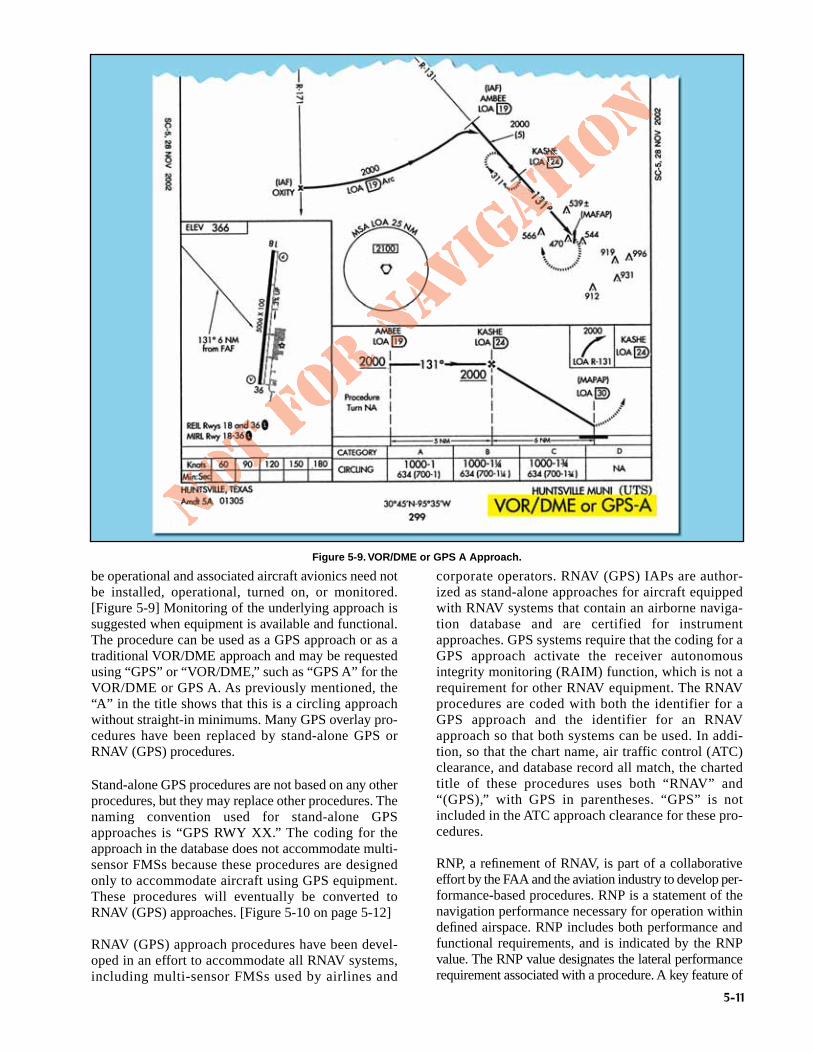
GPS overlay procedures that are based on pre-existingnonprecision approaches contain the wording “or GPS”in the title. For instance, the title “VOR/DME or GPSA” denotes that throughout the GPS approach, theunderlying ground-based NAVAIDs are not required to
Figure 5-8. VOR/DME RNAV Approach Chart.
Figure 5-7. Procedures without Straight-in Landing Minimums.
5-11
be operational and associated aircraft avionics need notbe installed, operational, turned on, or monitored.[Figure 5-9] Monitoring of the underlying approach issuggested when equipment is available and functional.The procedure can be used as a GPS approach or as atraditional VOR/DME approach and may be requestedusing “GPS” or “VOR/DME,” such as “GPS A” for theVOR/DME or GPS A. As previously mentioned, the“A” in the title shows that this is a circling approachwithout straight-in minimums. Many GPS overlay pro-cedures have been replaced by stand-alone GPS orRNAV (GPS) procedures.
Stand-alone GPS procedures are not based on any otherprocedures, but they may replace other procedures. Thenaming convention used for stand-alone GPSapproaches is “GPS RWY XX.” The coding for theapproach in the database does not accommodate multi-sensor FMSs because these procedures are designedonly to accommodate aircraft using GPS equipment.These procedures will eventually be converted toRNAV (GPS) approaches. [Figure 5-10 on page 5-12]
RNAV (GPS) approach procedures have been devel-oped in an effort to accommodate all RNAV systems,including multi-sensor FMSs used by airlines and
corporate operators. RNAV (GPS) IAPs are author-ized as stand-alone approaches for aircraft equippedwith RNAV systems that contain an airborne naviga-tion database and are certified for instrumentapproaches. GPS systems require that the coding for aGPS approach activate the receiver autonomousintegrity monitoring (RAIM) function, which is not arequirement for other RNAV equipment. The RNAVprocedures are coded with both the identifier for aGPS approach and the identifier for an RNAVapproach so that both systems can be used. In addi-tion, so that the chart name, air traffic control (ATC)clearance, and database record all match, the chartedtitle of these procedures uses both “RNAV” and“(GPS),” with GPS in parentheses. “GPS” is notincluded in the ATC approach clearance for these pro-cedures.
RNP, a refinement of RNAV, is part of a collaborativeeffort by the FAA and the aviation industry to develop per-formance-based procedures. RNP is a statement of thenavigation performance necessary for operation withindefined airspace. RNP includes both performance andfunctional requirements, and is indicated by the RNPvalue. The RNP value designates the lateral performancerequirement associated with a procedure. A key feature of
Figure 5-9. VOR/DME or GPS A Approach.

5-12
RNP is the concept of on-board monitoring and alerting.This means the navigation equipment is accurate enoughto keep the aircraft in a specific volume of airspace, whichmoves along with the aircraft. The aircraft is expected toremain within this volume of airspace for at least 95 per-cent of the flight time, and the integrity of the systemensures the aircraft will do so. The aircraft avionics alsocontinuously monitor sensor inputs, and through complexfiltering, generate an indication in the level of confidencein the navigation performance sometimes referred to asactual navigation performance (ANP). An essential func-tion required for RNP operations is the ability of the sys-tem to alert the pilot when the ANP exceeds the requisiteRNP value.
Navigation performance for a particular RNP type isexpressed numerically. Depending on the capability ofeach aircraft's system, RNP values can be as low as 0.1 ofa nautical mile. A performance value of RNP 0.3, forexample assures that the aircraft has the capability ofremaining within 0.3 of a nautical mile to the right or leftside of the centerline 95 percent of the time.
COMMUNICATIONSThe communication strip provided near the top ofNACO approach charts gives flight crews the fre-quencies that they can expect to be assigned duringthe approach. The frequencies are listed in the logi-cal order of use from arrival to touchdown. Havingthis information immediately available during theapproach reduces the chances of a loss of contactbetween ATC and flight crews during this criticalphase of flight.
It is important for flight crews to understand theirresponsibilities with regard to communications inthe various approach environments. There arenumerous differences in communication responsibil-ities when operating into and out of airports withoutair traffic control towers as compared to airportswith control towers. Today’s professional pilots facean ever-increasing range of ATC environments andconflicting traffic dangers, making approach
briefing and preplanning even more critical.Individual company operating manuals and SOPsdictate the duties for each crewmember.
Advisory Circular 120-71, Standard OperatingProcedures for Flight Deck Crewmembers, contains thefollowing concerning ATC communications:
APPROACH CONTROLApproach control is responsible for controlling allinstrument flights operating within its area ofresponsibility. Approach control may serve one ormore airports. Control is exercised primarily throughdirect pilot and controller communication and air-port surveillance radar (ASR). Prior to arriving at theIAF, instructions will be received from ARTCC to
ATC Communications: SOPs should state whohandles the radios for each phase of flight (pilotflying [PF], pilot monitoring [PM], flight engi-neer/second officer (FE/SO), as follows:
PF makes input to aircraft/autopilot and/or ver-bally states clearances while PM confirms inputis what he/she read back to ATC.
Any confusion in the flight deck is immediatelycleared up by requesting ATC confirmation.
If any crewmember is off the flight deck, all ATCinstructions are briefed upon his/her return. Or ifany crewmember is off the flight deck all ATCinstructions are written down until his/her returnand then passed to that crewmember uponreturn. Similarly, if a crewmember is off ATC fre-quency (e.g., when making a PA announcementor when talking on company frequency), all ATCinstructions are briefed upon his/her return.
Company policy should address use ofspeakers, headsets, boom mike and/orhand-held mikes.
Figure 5-10. GPS Stand-alone Approach.

5-13
contact approach control on a specified frequency.Where radar is approved for approach controlservice, it is used not only for radar approaches,but also for vectors in conjunction with published non-radar approaches using conventional NAVAIDs orRNAV/GPS.
When radar handoffs are initiated between the ARTCCand approach control, or between two approach controlfacilities, aircraft are cleared (with vertical separation)to an outer fix most appropriate to the route being flownand, if required, given holding instructions. Or, aircraftare cleared to the airport or to a fix so located that thehandoff will be completed prior to the time the aircraftreaches the fix. When radar handoffs are used, succes-sive arriving flights may be handed off to approachcontrol with radar separation in lieu of vertical separa-tion.
After release to approach control, aircraft are vectoredto the final approach course. ATC will occasionallyvector the aircraft across the final approach course forspacing requirements. The pilot is not expected to turninbound on the final approach course unless anapproach clearance has been issued. This clearance willnormally be issued with the final vector for intercep-tion of the final approach course, and the vector willenable the pilot to establish the aircraft on the finalapproach course prior to reaching the FAF.
AIR ROUTE TRAFFIC CONTROL CENTERARTCCs are approved for and may provide approachcontrol services to specific airports. The radar systemsused by these Centers do not provide the same preci-sion as an ASR or precision approach radar (PAR) usedby approach control facilities and control towers, andthe update rate is not as fast. Therefore, pilots may berequested to report established on the final approachcourse. Whether aircraft are vectored to the appropriatefinal approach course or provide their own navigationon published routes to it, radar service is automaticallyterminated when the landing is completed; or wheninstructed to change to advisory frequency at airportswithout an operating air traffic control tower,whichever occurs first. When arriving on an IFR flightplan at an airport with an operating control tower, theflight plan will be closed automatically upon landing.
The extent of services provided by approach controlvaries greatly from location to location. The majority ofPart 121 operations in the NAS use airports that haveradar service and approach control facilities to assistin the safe arrival and departure of large numbers ofaircraft. Many airports do not have approach controlfacilities. It is important for pilots to understand thedifferences between approaches with and without anapproach control facility. For example, consider theDurango, Colorado, ILS DME RWY 2 and low alti-tude en route chart excerpt, shown in figure 5-11.
• High or lack of minimum vectoring altitudes(MVAs) – Considering the fact that most moderncommercial and corporate aircraft are capable ofdirect, point-to-point flight, it is increasinglyimportant for pilots to understand the limitationsof ARTCC capabilities with regard to mini-mum altitudes. There are many airports thatare below the coverage area of Center radar,and, therefore, off-route transitions into theapproach environment may require that theaircraft be flown at a higher altitude thanwould be required for an on-route transition.In the Durango example, an airplane approach-ing from the northeast on a direct route to theDurango VOR may be restricted to a minimumIFR altitude (MIA) of 17,000 feet mean sealevel (MSL) due to unavailability of Center radarcoverage in that area at lower altitudes. Anarrival on V95 from the northeast would be able todescend to a minimum en route altitude (MEA)of 12,000 feet, allowing a shallower transitionto the approach environment. An off-routearrival may necessitate a descent in the pub-lished holding pattern over the DRO VOR toavoid an unstable approach into Durango.
• Lack of approach control terrain advisories –Flight crews must understand that terrainclearance cannot be assured by ATC when air-craft are operating at altitudes that are notserved by Center or approach radar. Strictadherence to published routes and minimumaltitudes is necessary to avoid a controlledflight into terrain (CFIT) accident. Flightcrews should always familiarize themselveswith terrain features and obstacles depicted onapproach charts prior to initiating the approach.Approaches outside of radar surveillance requireenhanced awareness of this information.
• Lack of approach control traffic advisories – Ifradar service is not available for the approach, theability of ATC to give flight crews accurate trafficadvisories is greatly diminished. In some cases,the common traffic advisory frequency (CTAF)may be the only tool available to enhance an IFRflight’s awareness of traffic at the destinationairport. Additionally, ATC will not clear anIFR flight for an approach until the preced-ing aircraft on the approach has cancelledIFR, either on the ground, or airborne once invisual meteorological conditions (VMC).
AIRPORTS WITH AN AIR TRAFFIC CONTROL TOWERTowers are responsible for the safe, orderly, and expe-ditious flow of all traffic that is landing, taking off,operating on and in the vicinity of an airport and, whenthe responsibility has been delegated, towers

5-14
also provide for the separation of IFR aircraft interminal areas. Aircraft that are departing IFRare integrated into the departure sequence by thetower. Prior to takeoff, the tower controllercoordinates with departure control to assureadequate aircraft spacing.
AIRPORTS WITHOUT AN AIR TRAFFIC CONTROL TOWERFrom a communications standpoint, executing aninstrument approach to an airport that is not served byan ATC tower requires more attention and care than
making a visual approach to that airport. Pilots areexpected to self-announce their arrival into the vicinityof the airport no later than 10 NM from the field.Depending on the weather, as well as the amount andtype of conflicting traffic that exists in the area, anapproach to an airport without an operating ATC towerwill increase the difficulty of the transition to visualflight. In many cases, a flight arriving via an instrumentapproach will need to mix in with visual flight rules(VFR) traffic operating in the vicinity of the field. Forthis reason, many companies require that flight crewsmake contact with the arrival airport CTAF or company
Figure 5-11. Durango Approach and Low Altitude En Route Chart Excerpt.

5-15
operations personnel via a secondary radio over 25 NMfrom the field in order to receive traffic advisories. Inaddition, pilots should attempt to listen to the CTAFwell in advance of their arrival in order to determinethe VFR traffic situation.
Since separation cannot be provided by ATC between IFRand VFR traffic when operating in areas where there is noradar coverage, pilots are expected to make radioannouncements on the CTAF. These announcementsallow other aircraft operating in the vicinity to plan theirdepartures and arrivals with a minimum of conflicts. Inaddition, it is very important for crews to maintain a lis-tening watch on the CTAF to increase their awareness ofthe current traffic situation. Flights inbound on an instru-ment approach to a field without a control tower shouldmake several self-announced radio calls during theapproach:
• Initial call within 5-10 minutes of the aircraft’sarrival at the IAF. This call should give the air-craft’s location as well as the crew’s approachintentions.
• Departing the IAF, stating the approach that isbeing initiated.
• Procedure turn (or equivalent) inbound.
• FAF inbound, stating intended landing runwayand maneuvering direction if circling.
• Short final, giving traffic on the surface notifica-tion of imminent landing.
When operating on an IFR flight plan at an airportwithout a functioning control tower, pilots must initi-ate cancellation of the IFR flight plan with ATC or anAFSS. Remote communications outlets (RCOs) orground communications outlets (GCOs), if available,can be used to contact an ARTCC or an AFSS afterlanding. If a frequency is not available on the ground,the pilot has the option to cancel IFR while in flight ifVFR conditions can be maintained while in contactwith ARTCC, as long as those conditions can be main-tained until landing. Additionally, pilots can relay amessage through another aircraft or contact flightservice via telephone.
PRIMARY NAVAIDMost conventional approach procedures are builtaround a primary final approach NAVAID; others, suchas RNAV (GPS) approaches, are not. If a primaryNAVAID exists for an approach, it should be includedin the IAP briefing, set into the appropriate backup oractive navigation radio, and positively identified atsome point prior to being used for course guidance.Adequate thought should be given to the appropriatetransition point for changing from FMS or other enroute navigation over to the conventional navigation tobe used on the approach. Specific company standards
and procedures normally dictate when this changeoveroccurs; some carriers are authorized to use FMS courseguidance throughout the approach, provided that anindication of the conventional navigation guidance isavailable and displayed. Many carriers, or specificcarrier fleets, are required to change over fromRNAV to conventional navigation prior to the FAFof an instrument approach.
Depending on the complexity of the approach proce-dure, pilots may have to brief the transition from aninitial NAVAID to the primary and missed approachNAVAIDs. Figure 5-12 shows the Cheyenne,Wyoming, ILS Runway 27 approach procedure,which requires additional consideration during anIAP briefing.
If the 15 DME arc of the CYS VOR is to be used as thetransition to this ILS approach procedure, caution mustbe paid to the transition from en route navigation to theinitial NAVAID and then to the primary NAVAID forthe ILS approach. Planning when the transition to eachof these NAVAIDs occurs may prevent the use of theincorrect NAVAID for course guidance duringapproaches where high pilot workloads already exist.
APPROACH CHART NOTESThe navigation equipment that is required to join and flyan instrument approach procedure is indicated by the titleof the procedure and notes on the chart. Straight-in IAPsare identified by the navigation system by providing thefinal approach guidance and the runway with which theapproach is aligned (for example, VOR RWY 13).Circling-only approaches are identified by the navigationsystem by providing final approach guidance and a letter(for example, VOR A). More than one navigation systemseparated by a slant indicates that more than one type ofequipment must be used to execute the final approach (forexample, VOR/DME RWY 31). More than one naviga-tion system separated by the word “or” indicates eithertype of equipment can be used to execute the finalapproach (for example, VOR or GPS RWY 15).
In some cases, other types of navigation systems, includ-ing radar, are required to execute other portions of theapproach or to navigate to the IAF (for example, an NDBprocedure turn to an ILS, or an NDB in the missedapproach, or radar required to join the procedure or iden-tify a fix). When ATC radar or other equipment is requiredfor procedure entry from the en route environment, a noteis charted in the planview of the approach procedure chart(for example, RADAR REQUIRED or ADFREQUIRED). When radar or other equipment is requiredon portions of the procedure outside the final approachsegment, including the missed approach, a note is chartedin the notes box of the pilot briefing portion of theapproach chart (for example, RADAR REQUIRED orDME REQUIRED). Notes are not charted when VOR is

5-16
required outside the final approach segment. Pilots shouldensure that the aircraft is equipped with the requiredNAVAIDs to execute the approach, including the missedapproach.
COURSESAn aircraft that has been cleared to a holding fix andsubsequently “cleared…approach,” normally does notreceive new routing. Even though clearance for theapproach may have been issued prior to the aircraftreaching the holding fix, ATC would expect the pilot toproceed via the holding fix which was the last assignedroute, and the feeder route associated with that fix, if afeeder route is published on the approach chart, to theIAF to commence the approach. When cleared for theapproach, the published off-airway (feeder) routes thatlead from the en route structure to the IAF are part ofthe approach clearance.
If a feeder route to an IAF begins at a fix located alongthe route of flight prior to reaching the holding fix, andclearance for an approach is issued, a pilot should com-mence the approach via the published feeder route; for
example, the aircraft would not be expected to overflythe feeder route and return to it. The pilot is expected tocommence the approach in a similar manner at the IAF,if the IAF for the procedure is located along the routeof flight to the holding fix.
If a route of flight directly to the IAF is desired, itshould be so stated by the controller with phraseologyto include the words “direct,” “proceed direct,” or asimilar phrase that the pilot can interpret without ques-tion. When a pilot is uncertain of the clearance, ATCshould be queried immediately as to what route offlight is preferred.
The name of an instrument approach, as published, isused to identify the approach, even if a component ofthe approach aid is inoperative or unreliable. The con-troller will use the name of the approach as published,but must advise the aircraft at the time an approachclearance is issued that the inoperative or unreliableapproach aid component is unusable. (Example:“Cleared ILS RWY 4, glide slope unusable.”)
Figure 5-12. Cheyenne (KCYS), Cheyenne, Wyoming, ILS or LOC RWY 27.
5-17
AREA NAVIGATION COURSESRNAV (GPS) approach procedures introduce their owntracking issues because they are flown using anonboard navigation database. They may be flown ascoupled approaches or flown manually. In either case,navigation system coding is based on procedure design,including waypoint (WP) sequencing for an approachand missed approach. The procedure design will indi-cate whether the WP is a fly-over or fly-by, and willprovide appropriate guidance for each. A fly-by (FB)waypoint requires the use of turn anticipation to avoidovershooting the next flight segment. A fly-over (FO)waypoint precludes any turn until the waypoint is over-flown, and is followed by either an intercept maneuverof the next flight segment or direct flight to the nextwaypoint.
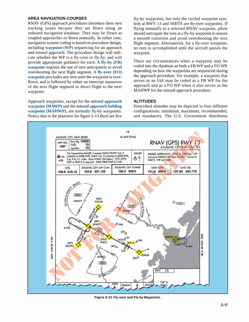
Approach waypoints, except for the missed approachwaypoint (MAWP) and the missed approach holdingwaypoint (MAHWP), are normally fly-by waypoints.Notice that in the planview for figure 5-13 there are five
fly-by waypoints, but only the circled waypoint sym-bols at RWY 13 and SMITS are fly-over waypoints. Ifflying manually to a selected RNAV waypoint, pilotsshould anticipate the turn at a fly-by waypoint to ensurea smooth transition and avoid overshooting the nextflight segment. Alternatively, for a fly-over waypoint,no turn is accomplished until the aircraft passes thewaypoint.
There are circumstances when a waypoint may becoded into the database as both a FB WP and a FO WP,depending on how the waypoints are sequenced duringthe approach procedure. For example, a waypoint thatserves as an IAF may be coded as a FB WP for theapproach and as a FO WP when it also serves as theMAHWP for the missed approach procedure.
ALTITUDESPrescribed altitudes may be depicted in four differentconfigurations: minimum, maximum, recommended,and mandatory. The U.S. Government distributes
Figure 5-13. Fly-over and Fly-by Waypoints.

5-18
approach charts produced by the National Geospatial-Intelligence Agency (NGA) and NACO. Altitudes aredepicted on these charts in the profile view with under-score, overscore, or both to identify them as minimum,maximum, or mandatory, respectively.
• Minimum altitudes are depicted with the altitudevalue underscored. Aircraft are required to main-tain altitude at or above the depicted value.
• Maximum altitudes are depicted with the altitudevalue overscored. Aircraft are required to main-tain altitude at or below the depicted value.
• Mandatory altitudes are depicted with the altitudevalue both underscored and overscored. Aircraftare required to maintain altitude at the depictedvalue.
• Recommended altitudes are depicted without anunderscore or overscore.
NOTE: The underscore and overscore used toidentify mandatory altitudes and overscore toidentify maximum altitudes are used almostexclusively by the NGA for military charts.Pilots are cautioned to adhere to altitudes as pre-scribed because, in certain instances, they maybe used as the basis for vertical separation ofaircraft by ATC. When a depicted altitude isspecified in the ATC clearance, that altitudebecomes mandatory as defined above.
MINIMUM SAFE ALTITUDEMinimum safe altitudes (MSAs) are published foremergency use on IAP charts. For conventional naviga-tion systems, the MSA is normally based on theprimary omnidirectional facility on which the IAP ispredicated. The MSA depiction on the approach chartcontains the facility identifier of the NAVAID used todetermine the MSA. For RNAV approaches, the MSA isbased on either the runway waypoint (RWY WP) or themissed approach waypoint (MAWP) for straight-inapproaches, or the airport waypoint (APT WP) for cir-cling only approaches. For RNAV (GPS) approacheswith a terminal arrival area (TAA) the MSA is based onthe IAF waypoint.
MSAs are expressed in feet above MSL and normallyhave a 25 NM radius. This radius may be expanded to30 NM if necessary to encompass the airport landingsurfaces. Ideally, a single sector altitude is establishedand depicted on the planview of approach charts. Whennecessary to maintain clearance from obstructions, thearea may be further sectored and as many as four MSAsestablished. When established, sectors may be no lessthan 90°in spread. MSAs provide 1,000 feet clearanceover all obstructions but do not necessarily assureacceptable navigation signal coverage.
FINAL APPROACH FIX ALTITUDEAnother important altitude that should be briefedduring an IAP briefing is the FAF altitude, designatedby the cross on a nonprecision approach, and the light-ning bolt symbol designating the glide slope interceptaltitude on a precision approach. Adherence to andcrosscheck of this altitude can have a direct effect onthe success of an approach.
Proper airspeed, altitude, and configuration, whencrossing the FAF of a nonprecision approach, areextremely important no matter what type of aircraft isbeing flown. The stabilized approach concept, imple-mented by the FAA within the SOPs of each air carrier,suggests that crossing the FAF at the published altitudeis often a critical component of a successful non-precision approach, especially in a large turbojetaircraft.
The glide slope intercept altitude of a precisionapproach should also be included in the IAP briefing.Awareness of this altitude when intercepting the glideslope can ensure the flight crew that a “false glideslope” or other erroneous indication is not inadver-tently followed. Many air carriers include a standardcallout when the aircraft passes over the FAF of thenonprecision approach underlying the ILS. The pilotmonitoring (PM) states the name of the fix and thecharted glide slope altitude, thus allowing both pilots tocrosscheck their respective altimeters and verify thecorrect indications.
MINIMUM DESCENT ALTITUDE, DECISION ALTITUDE,AND DECISION HEIGHTMDA and DA are referenced to MSL and measuredwith a barometric altimeter. CAT II and IIIapproach DHs are referenced to AGL and measuredwith a radio altimeter.
The height above touchdown (HAT) for a CAT Iprecision approach is normally 200 feet abovetouchdown zone elevation (TDZE). When a HAT of250 feet or higher is published, it may be the resultof the signal-in-space coverage, or there may bepenetrations of either the final or missed approachobstacle clearance surfaces (OCSs). If there areOCS penetrations, the pilot will have no indicationon the approach chart where the obstacles arelocated. It is important for pilots to brief the MDA,DA, or DH so that there is no ambiguity as to whatminimums are being used. These altitudes can berestricted by many factors. Approach category,inoperative equipment in the aircraft or on theground, crew qualifications, and company authorizationsare all examples of issues that may limit or change theheight of a published MDA, DA, or DH.

5-19
The primary authorization for the use of specificapproach minimums by an individual air carrier can befound in Part C–Airplane Terminal InstrumentProcedures, Airport Authorizations and Limitations, ofits FAA approved OpsSpecs. This document lists the
lowest authorized landing minimums that the carriercan use while conducting instrument approaches.Figure 5-14 shows an example of a carrier’s OpsSpecsthat lists minimum authorized MDAs and visibilitiesfor nonprecision approaches.
Figure 5-14. Authorized Landing Minimums for Nonprecision Approaches.

5-20
As can be seen from the previous example, theOpsSpecs of this company rarely restrict it from usingthe published MDA for a nonprecision approach. Inother words, most, if not all, nonprecision approachesthat pilots for this company fly have published MDAsthat meet or exceed its lowest authorized minimums.Therefore the published minimums are the limiting fac-tor in these cases.
For many air carriers, OpsSpecs may be the limitingfactor for some types of approaches. NDB and circlingapproaches are two common examples where theOpsSpecs minimum listed altitudes may be morerestrictive than the published minimums. Many Part121 and 135 operators are restricted from conductingcircling approaches below 1,000-feet MDA and 3 SMvisibility by Part C of their OpsSpecs, and many havespecific visibility criteria listed for NDB approachesthat exceed visibilities published for the approach(commonly 2 SM). In these cases, flight crews mustdetermine which is the more restrictive of the two andcomply with those minimums.
In some cases, flight crew qualifications can bethe limiting factor for the MDA, DA, or DH for aninstrument approach. There are many CAT II andIII approach procedures authorized at airportsthroughout the U.S., but Special Aircraft andAircrew Authorization Requirements (SAAAR)restrict their use to pilots who have received specifictraining, and aircraft that are equipped and author-ized to conduct those approaches. Other rules per-taining to flight crew qualifications can alsodetermine the lowest usable MDA, DA, or DH fora specific approach. Parts 121.652, 125.379, and135.225 require that some pilots-in-command,with limited experience in the aircraft they areoperating, increase the approach minimums andvisibility by 100 feet and one-half mile respec-tively. Rules for these “high-minimums” pilotsare usually derived from a combination of fed-eral regulations and the company’s OpsSpecs.There are many factors that can determine the actualminimums that can be used for a specific approach.All of them must be considered by pilots during thepreflight and approach planning phases, discussed,and briefed appropriately.
VERTICAL NAVIGATIONOne of the advantages of some GPS and multi-sen-sor FMS RNAV avionics is the advisory VNAVcapability. Traditionally, the only way to get verti-cal path information during an approach was to usea ground-based precision NAVAID. Modern RNAVavionics can display an electronic vertical path thatprovides a constant-rate descent to minimums.
Since these systems are advisory and not primaryguidance, the pilot must continuously ensure theaircraft remains at or above any published altitudeconstraint, including step-down fix altitudes, usingthe primary barometric altimeter. The pilots, air-plane, and operator must be approved to use advi-sory VNAV inside the FAF on an instrumentapproach.
VNAV information appears on selected conven-tional nonprecision, GPS, and RNAV approaches(see Types of Approaches later in this chapter). Itnormally consists of two fixes (the FAF and thelanding runway threshold), a FAF crossing altitude,a vertical descent angle (VDA), and may provide avisual descent point (VDP). [Figure 5-15] The pub-lished VDA is for information only, advisory innature, and provides no additional obstacle protec-tion below the MDA. Operators can be approved toadd a height loss value to the MDA, and use thisderived decision altitude (DDA) to ensure stayingabove the MDA. Operators authorized to use aVNAV DA in lieu of the MDA must commence amissed approach immediately upon reaching theVNAV DA if the required visual references to con-tinue the approach have not been established.
A constant-rate descent has many safety advantagesover nonprecision approaches that require multiplelevel-offs at stepdown fixes or manually calculatingrates of descent. A stabilized approach can be main-tained from the FAF to the landing when a constant-rate descent is used. Additionally, the use of anelectronic vertical path produced by onboard avion-ics can serve to reduce CFIT, and minimize theeffects of visual illusions on approach and landing.
WIDE AREA AUGMENTATION SYSTEMIn addition to the benefits that VNAV information pro-vides for conventional nonprecision approaches,VNAV has a significant effect on approaches that aredesigned specifically for RNAV systems. Using anFMS or GPS that can provide both lateral navigation(LNAV) and VNAV, some RNAV approaches allowdescents to lower MDAs or DAs than when usingLNAV alone. The introduction of the Wide AreaAugmentation System (WAAS), which became opera-tional on July 10, 2003, provides even lower mini-mums for RNAV approaches that use GPS byproviding electronic vertical guidance and increasedaccuracy.
The Wide Area Augmentation System, as its nameimplies, augments the basic GPS satellite constella-tion with additional ground stations and enhanced

5-21
position integrity information transmitted fromgeostationary satellites. This capability of augmen-tation enhances both the accuracy and integrity ofbasic GPS, and may support electronic verticalguidance approach minimums as low as 200 feetHAT and 1/2 SM visibility. In order to achieve thelowest minimums, the requirements of an entireelectronic vertical guidance system, includingsatellite availability; clear obstruction surfaces; AC150/5300-13, Airport Design; and electronic verti-cal guidance runway and airport requirements,must be satisfied. The minimums are shown as DAssince electronically computed glidepath guidanceis provided to the pilot. The electronically computedguidance eliminates errors that can be introducedwhen using barometric altimetry.
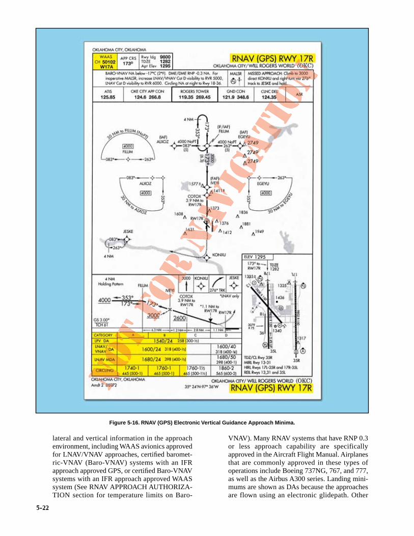
RNAV (GPS) approach charts presently can have up tofour lines of approach minimums: LPV, LNAV/VNAV,LNAV, and Circling. Figure 5-16 shows how these min-imums might be presented on an approach chart, withthe exception of GLS.
• GLS — The acronym GLS stands for The GlobalNavigation Satellite System [GNSS] LandingSystem (GLS). GLS is a satellite based naviga-tion system that provides course and glidepathinformation meeting the precision standards ofICAO Annex 10. Procedures based on the localarea augmentation system (LAAS) will becharted separately under the GLS title as thesesystems are implemented.
NOTE: On RNAV approach charts the GLS min-ima line has been used as a placeholder only. AsWAAS procedures are developed, LPV lines ofminima will replace the “GLS DA-NA” lines ofminima.
• LPV — APV minimums that take advantage ofWAAS to provide electronic lateral and verticalguidance capability. The term “LPV” (localizerperformance with vertical guidance) is used forapproaches constructed with WAAS criteriawhere the value for the vertical alarm limit ismore than 12 meters and less than 50 meters.WAAS avionics equipment approved for LPVapproaches is required for this type of approach.The lateral guidance is equivalent to localizeraccuracy, and the protected area is considerablysmaller than the protected area for the presentLNAV and LNAV/VNAV lateral protection.Aircraft can fly this minima line with a statementin the Aircraft Flight Manual that the installedequipment supports LPV approaches. Notice theWAAS information shown in the top left cornerof the pilot briefing information on the chartdepicted. Below the term WAAS is the WAASchannel number (CH 50102), and the WAASapproach identifier (W17A), indicating Runway17R in this case, and then a letter to designate thefirst in a series of procedures to that runway.
• LNAV/VNAV — APV minimums used by air-craft with RNAV equipment that provides both
Figure 5-15. VNAV Information.
5-22
lateral and vertical information in the approachenvironment, including WAAS avionics approvedfor LNAV/VNAV approaches, certified baromet-ric-VNAV (Baro-VNAV) systems with an IFRapproach approved GPS, or certified Baro-VNAVsystems with an IFR approach approved WAASsystem (See RNAV APPROACH AUTHORIZA-TION section for temperature limits on Baro-
VNAV). Many RNAV systems that have RNP 0.3or less approach capability are specificallyapproved in the Aircraft Flight Manual. Airplanesthat are commonly approved in these types ofoperations include Boeing 737NG, 767, and 777,as well as the Airbus A300 series. Landing mini-mums are shown as DAs because the approachesare flown using an electronic glidepath. Other
Figure 5-16. RNAV (GPS) Electronic Vertical Guidance Approach Minima.

RNAV systems require special approval. In somecases, the visibility minimums for LNAV/VNAVmight be greater than those for LNAV only. Thissituation occurs because DA on the LNAV/VNAVvertical descent path is farther away from the run-way threshold than the LNAV MDA missedapproach point.
• LNAV — minimums provided for RNAVsystems that do not produce any VNAVinformation. IFR approach approved GPS,WAAS, or RNP 0.3 systems are required.Because vertical guidance is not provided,the procedure minimum altitude is pub-lished as an MDA. These minimums areused in the same manner as conventionalnonprecision approach minimums. OtherRNAV systems require special approval.
• Circling — minimums that may be used with anytype of approach approved RNAV equipmentwhen publication of straight-in approach mini-mums is not possible.
REQUIRED NAVIGATION PERFORMANCEThe operational advantages of RNP include accuracyand integrity monitoring, which provide more preci-sion and lower minimums than conventional RNAV.RNP DAs can be as low as 250 feet with visibilities aslow as 3/4 SM. Besides lower minimums, the benefitsof RNP include improved obstacle clearance limits, aswell as reduced pilot workload. When RNP-capableaircraft fly an accurate, repeatable path, ATC can beconfident that these aircraft will be at a specific posi-tion, thus maximizing safety and increasing capacity.
To attain the benefits of RNP approach procedures, akey component is curved flight tracks. Constant radiusturns around a fix are called “radius-to-fix legs,” or RFlegs. These turns, which are encoded into the naviga-tion database, allow the aircraft to avoid critical areasof terrain or conflicting airspace while preserving posi-tional accuracy by maintaining precise, positive courseguidance along the curved track. The introduction ofRF legs into the design of terminal RNAV proceduresresults in improved use of airspace and allows proce-dures to be developed to and from runways that are oth-erwise limited to traditional linear flight paths or, insome cases, not served by an IFR procedure at all.Navigation systems with RF capability are a prerequi-site to flying a procedure that includes an RF leg. Referto the notes box of the pilot briefing portion of theapproach chart in figure 5-17.
In the United States, all RNP procedures are in the cat-egory of Special Aircraft and Aircrew AuthorizationRequired (SAAAR). Operators who seek to take advan-
tage of RNP approach procedures must meet the spe-cial RNP requirements outlined in FAA AC 90-101,Approval Guidance for RNP Procedures with SAAAR.Currently, most new transport category airplanesreceive an airworthiness approval for RNP operations.However, differences can exist in the level of precisionthat each system is qualified to meet. Each individualoperator is responsible for obtaining the necessaryapproval and authorization to use these instrumentflight procedures with navigation databases.
RNAV APPROACH AUTHORIZATIONLike any other authorization given to air carriers and Part91 operators, the authorization to use VNAV on a con-ventional nonprecision approach, RNAV approaches, orLNAV/VNAV approaches is found in that operator’sOpsSpecs, AFM, or other FAA-approved documents.There are many different levels of authorizations whenit comes to the use of RNAV approach systems. Thetype of equipment installed in the aircraft, the redun-dancy of that equipment, its operational status, the levelof flight crew training, and the level of the operator’sFAA authorization are all factors that can affect apilot’s ability to use VNAV information on anapproach.
Because most Part 121, 125, 135, and 91 flight depart-ments include RNAV approach information in theirpilot training programs, a flight crew considering anapproach to North Platte, Nebraska, using the RNAV(GPS) RWY 30 approach shown in figure 5-18, wouldalready know which minimums they were authorizedto use. The company’s OpsSpecs, Flight OperationsManual, and the AFM for the pilot’s aircraft woulddictate the specific operational conditions andprocedures by which this type of approach couldbe flown.
There are several items of note that are specific to thistype of approach that should be considered and briefed.One is the terminal arrival area (TAA) that is dis-played in the approach planview. TAAs, discussed laterin this chapter, depict the boundaries of specific arrivalareas, and the MIA for those areas. The TAAs shouldbe included in an IAP briefing in the same manner asany other IFR transition altitude. It is also important tonote that the altitudes listed in the TAAs should bereferenced in place of the MSAs on the approachchart for use in emergency situations.
In addition to the obvious differences contained in theplanview of the previous RNAV (GPS) approach proce-dure example, pilots should be aware of the issuesrelated to Baro-VNAV and RNP. The notes section ofthe procedure in the example contains restrictionsrelating to these topics.
5-23

5-24
RNP values for each individual leg of the procedure, defined by the procedure design criteria for containment purposes, are encoded into the aircraft's naviga-tion database. Applicable landing minimums are shown in a normal manner along with the associated RNP value in the landing minimums section. When more than one set of RNP landing minimums is available and an aircrew is able to achieve lower RNP through approved means, the available (multiple) sets of RNP minimums are listed with the lowest set shown first; remaining sets shown in ascending order, based on the RNP value.
On this particular procedure, lateral and vertical course guidance from the DA to the Runway Waypoint (Landing Threshold Point or LTP) is provided by the aircraft's FMS and onboard navigation database; however, any continued flight beyond and below the DA to the landing threshold is to be conducted under visual meteorological conditions (VMC).
RNP-required sensors, FMS capabilities, and relevant procedure notes are included in the Pilot Briefing Information procedure notes section.
RNP SAAAR requirements are highlighted in large, bold print.
RNP procedures are sequenced in the same manner as RNAV (GPS) procedures.
Procedure title “RNAV” includes parenthetical “(RNP)” terminology.
RF legs can be used in any segment of the procedure (transition, intermediate, final, or missed approach). RF leg turn directions (left or right) are not noted in the planview because the graphic depiction of the flight tracks is intuitive. Likewise, the arc center points, arc radius, and associated RF leg performance limits—such as bank angles and speeds—are not depicted because these aircraft performance characteris-tics are encoded in the navigation database.
Figure 5-17. RNAV (RNP) Approach Procedure with Curved Flight Tracks.

5-25
Baro-VNAV avionics provide advisory VNAV pathindications to the pilot referencing a procedure’svertical path angle (VPA). The computer calculatedvertical guidance is based on barometric altitude,and is either computed as a geometric path betweentwo waypoints or an angle from a single waypoint. Ifa flight crew is authorized to conduct VNAV
approaches using an RNAV system that falls into thiscategory, the Baro-VNAV temperature limitationslisted in the notes section of the approach procedureapply. Also, since Baro-VNAV is advisory guidance,the pilot must continuously crosscheck the primarybarometric altimeter to ensure compliance with allaltitude restrictions on an instrument procedure.
Figure 5-18. North Platte Regional (KLBF), North Platte, Nebraska, RNAV (GPS) RWY 30.

5-26
Considering the pronounced effect of cold temper-atures on Baro-VNAV operations, a minimumtemperature limitation is published for eachprocedure for which Baro-VNAV minimums arepublished. This temperature represents the airporttemperature below which the use of Baro-VNAVis not authorized to the LNAV/VNAV DA. Thenote “Baro-VNAV NA below -20°C (-4°F)”implies that the approach may not be flown at allusing Baro-VNAV when the temperature is below-20° Celsius. However, Baro-VNAV may be usedfor approach guidance down to the publishedLNAV MDA. This information can be seen in thenotes section of the previous example.
In the example for the RNAV (GPS) RWY 30approach, the note “DME/DME RNP-0.3 NA” pro-hibits aircraft that use only DME/DME sensors forRNAV from conducting the approach.
Because these procedures can be flown with anapproach approved RNP system and “RNP” is not sen-sor specific, it was necessary to add this note to make itclear that those aircraft deriving RNP 0.3 usingDME/DME only are not authorized to conduct the pro-cedure.
The lowest performing sensor authorized for RNP nav-igation is DME/DME. The necessary DME NAVAIDground infrastructure may or may not be available atthe airport of intended landing. The procedure designerhas a computer program for determining the usabilityof DME based on geometry and coverage. Where FAAFlight Inspection successfully determines that the cov-erage and accuracy of DME facilities support RNP, andthat the DME signal meets inspection tolerances,although there are none currently published, the note“DME/DME RNP 0.3 Authorized” would be charted.Where DME facility availability is a factor, the notewould read, “DME/DME RNP 0.3 Authorized; ABCand XYZ required,” meaning that ABC and XYZ DMEfacilities are required to assure RNP 0.3.
AIRPORT/RUNWAY INFORMATIONAnother important piece of a thorough approachbriefing is the discussion of the airport and runwayenvironment. A detailed examination of the runwaylength (this must include the Airport/FacilityDirectory for the landing distance available), theintended turnoff taxiway, and the route of taxi to theparking area, are all important briefing items. Inaddition, runway conditions should be discussed.The effect on the aircraft’s performance must beconsidered if the runway is wet or contaminated.
NACO approach charts include a runway sketch on eachapproach chart to make important airport informationeasily accessible to pilots. In addition, at airports thathave complex runway/taxiway configurations, a sepa-rate full-page airport diagram will be published.
The airport diagram also includes the latitude/longitudeinformation required for initial programming of FMSequipment. The included latitude/longitude grid showsthe specific location of each parking area on the airportsurface for use in initializing FMSs. Figure 5-19 showsthe airport sketch and diagram for Chicago-O’HareInternational Airport.
Pilots making approaches to airports that have this typeof complex runway and taxiway configuration mustensure that they are familiar with the airport diagramprior to initiating an instrument approach. A combina-tion of poor weather, high traffic volume, and highground controller workload makes the pilot’s job on theground every bit as critical as the one just performed inthe air.
INSTRUMENT APPROACH PROCEDUREBRIEFINGA thorough instrument approach briefing greatlyincreases the likelihood of a successful instrumentapproach. Most Part 121, 125, and 135 operators desig-nate specific items to be included in an IAP briefing, aswell as the order in which those items will be briefed.
Before an IAP briefing can begin, flight crews mustdecide which procedure is most likely to be flown fromthe information that is available to them. Most often,when the flight is being conducted into an airport thathas ATIS information, the ATIS will provide the pilotswith the approaches that are in use. If more than oneapproach is in use, the flight crew may have to make aneducated guess as to which approach will be issued tothem based on the weather, direction of their arrivalinto the area, any published airport NOTAMs, and pre-vious experience at the specific airport. If the crew is incontact with the approach control facility, they canquery ATC as to which approach is to be expected fromthe controller. Pilots may request specific approachesto meet the individual needs of their equipment orregulatory restrictions at any time and ATC will, inmost cases, be able to accommodate those requests,providing that workload and traffic permit.
If the flight is operating into an airport without a con-trol tower, the flight crew will occasionally be given thechoice of any available instrument approach at the field.In these cases, the flight crew must choose an appropri-ate approach based on the expected weather, aircraftperformance, direction of arrival, airport NOTAMs,and previous experience at the airport.
NAVIGATION AND COMMUNICATION RADIOSOnce the anticipated approach and runway have beenselected, each crewmember sets up their “side” of thecockpit. The pilots use information gathered fromATIS, dispatch (if available), ATC, the specificapproach chart for the approach selected, and any other

5-27
Figure 5-19. Airport Sketch and Diagram for Chicago-O’Hare International.

5-28
sources that are available. Company regulations dictatehow certain things are set up and others are left up topilot technique. In general, the techniques used at aspecific company are similar. This section addressestwo-pilot operations. During single-pilot IFR flights,the same items must be set up and the pilot should stilldo an approach briefing to verify that everything is setup correctly.
The number of items that can be set up ahead oftime depends on the level of automation of the air-craft and the avionics available. In a conventionalcockpit, the only things that can be set up, ingeneral, are the airspeed bugs (based on performancecalculations), altimeter bug (to DA, DH, or MDA),go around thrust/power setting, the radio altimeterbug (if installed and needed for the approach), andthe navigation/communication radios (if a standbyfrequency selector is available). The standby sideof the PF navigation radio should be set to theprimary NAVAID for the approach and the PMnavigation radio standby selector should be set toany other NAVAIDs that are required or available,and as dictated by company procedures, to add tothe overall situational awareness of the crew. Theautomatic direction finder (ADF) should also betuned to an appropriate frequency as required bythe approach, or as selected by the crew.
FLIGHT MANAGEMENT SYSTEMSIn addition to the items that are available on a conven-tional cockpit aircraft, glass-cockpit aircraft, as well asaircraft with an approved RNAV (GPS) system, usuallygive the crew the ability to set the final approach coursefor the approach selected and many other options toincrease situational awareness. Crews of FMSequipped aircraft have many options available as far assetting up the flight management computer (FMC),depending on the type of approach and companyprocedures. The PF usually programs the FMC forthe approach and the PM verifies the information.A menu of available approaches is usually availableto select from based on the destination airportprogrammed at the beginning of the flight or anew destination selected while en route.
The amount of information provided for theapproach varies from aircraft to aircraft, but thecrew can make modifications if something is notpre-programmed into the computer, such as addinga missed approach procedure or even building anentire approach for situational awareness purposesonly. The PF can also program a VNAV profile forthe descent and LNAV for segments that were notprogrammed during preflight, such as a standardterminal arrival route (STAR) or expected route tothe planned approach. Any crossing restrictions for
the STAR might need to be programmed as well.The most common crossing restrictions, whethermandatory or “to be expected,” are usually auto-matically programmed when the STAR is selected,but can be changed by ATC at any time. Other itemsthat need to be set up are dictated by aircraft-spe-cific procedures, such as autopilot, auto-throttles,auto-brakes, pressurization system, fuel system,seat belt signs, anti-icing/de-icing equipment,igniters, etc.
AUTOPILOT MODESIn general, an autopilot can be used to fly approacheseven if the FMC is inoperative (refer to the specificairplane’s minimum equipment list [MEL] to deter-mine authorization for operating with the FMCinoperative). Whether or not the FMC is available,use of the autopilot should be discussed during theapproach briefing, especially regarding the use of thealtitude pre-selector and auto-throttles, if equipped.The AFM for the specific airplane outlines proce-dures and limitations required for the use of theautopilot during an instrument approach in thataircraft.
There are just as many different autopilot modes toclimb or descend the airplane, as there are terms forthese modes (ex. Level Change [LVL CHG], VerticalSpeed [V/S], VNAV, Takeoff/Go Around [TO/GA],etc.). The pilot controls the airplane through theautopilot by selecting pitch modes and/or rollmodes, as well as the associated auto-throttle modes.This panel, sometimes called a mode control panel,is normally accessible to both pilots. Most aircraftwith sophisticated auto-flight systems and auto-throttles have the capability to select modes thatclimb the airplane with maximum climb thrust anddescend the airplane with the throttles at idle (LVLCHG, Flight Level Change [FL CHG], ManageLevel, etc.). They also have the capability to“capture,” or level off at pre-selected altitudes, aswell as track a LOC and glide slope (G/S) or a VORcourse. If the airplane is RNAV equipped, the autopilotwill also track the RNAV generated course. Most ofthese modes will be used at some point during aninstrument approach using the autopilot.Additionally, these modes can be used to provideflight director (FD) guidance to the pilot whilehand-flying the aircraft.
For the purposes of this precision approach example,the auto-throttles are engaged when the autopilot isengaged and specific airspeed and configurationchanges will not be discussed. The PF controlsairspeed with the speed selector on the mode con-trol panel and calls for flaps and landing gear as

5-29
needed, which the PM will select. The example infigure 5-20 begins with the airplane 5 NM northwestof BROWN at 4,500 feet with the autopilot engaged,and the flight has been cleared to track the Rwy 12LOC inbound. The current roll mode is LOC withthe PF’s NAV radio tuned to the LOC frequency of109.3; and the current pitch mode is altitude hold(ALT HOLD). Approach control clears the airplane
for the approach. The PF makes no immediatechange to the autopilot mode to prevent the aircraftfrom capturing a false glide slope; but the PM resetsthe altitude selector to 2,200 feet. The aircraft willremain level because the pitch mode remains in ALTHOLD until another pitch mode is selected. Uponreaching BROWN, the PF selects LVL CHG as thepitch mode. The auto-throttles retard to idle as the
Figure 5-20. Example Approaches Using Autopilot.

5-30
airplane begins a descent. Approaching 2,200 feet,the pitch mode automatically changes to altitudeacquire (ALT ACQ) then to ALT HOLD as theairplane levels at 2,200 feet. In addition to slow-ing the airplane and calling for configurationchanges, the PF selects approach mode (APP). Theroll mode continues to track the LOC and the pitchmode remains in ALT HOLD; however, the G/Smode arms. Selecting APP once the aircraft hasleveled at the FAF altitude is a suggested techniqueto ensure that the airplane captures the glide slopefrom below, and that a false glide slope is not beingtracked.
The PF should have the aircraft fully configured forlanding before intercepting the glide slope to ensure astabilized approach. As the airplane intercepts the glideslope, the pitch mode changes to G/S. Once the glideslope is “captured” by the autopilot, the PM can selectthe missed approach altitude in the altitude pre-selec-tor, as requested by the PF. The airplane will continueto track the glide slope. The minimum altitude at whichthe PF is authorized to disconnect the autopilot isairplane specific (Example, 50 feet below DA, DH,or MDA but not less than 50 feet AGL). The PF candisconnect the autopilot at any time prior to reachingthis altitude during a CAT I approach. The initialmissed approach is normally hand flown with flightdirector guidance unless both autopilots are engagedfor autoland during a CAT II or III approach.
The differences when flying the underlying nonpreci-sion approach begin when the aircraft has leveled offat 2,200 feet. Once ALT HOLD is annunciated theMDA is selected by the PM as requested by the PF. Itis extremely important for both pilots to beabsolutely sure that the correct altitude is selectedfor the MDA so that the airplane will not inadver-tently descend below the MDA. For aircraft that thealtitude pre-selector can only select 100-foot incre-ments, the MDA for this approach must be set at 800feet instead of 740 feet.
Vertical speed mode is used from the FAF inboundto allow for more precise control of the descent. Ifthe pilots had not selected the MDA in the altitudepre-selector window, the PF would not be able toinput a V/S and the airplane would remain level. Theautopilot mode will change from ALT ACQ to ALTHOLD as the airplane levels at 800 feet. Once ALTHOLD is annunciated, the PF calls for the missedapproach altitude of 4,000 feet to be selected in thealtitude pre-selector window. This step is veryimportant because accurate FD guidance will not beavailable to the PF during a missed approach if theMDA is left in the window.
NOTE: See Maximum Acceptable Descent Ratesunder the heading Descent Rates and Glidepaths forNonprecision Approaches.
STABILIZED APPROACHIn instrument meteorological conditions (IMC), youmust continuously evaluate instrument informationthroughout an approach to properly maneuver theaircraft (or monitor autopilot performance) and todecide on the proper course of action at the decisionpoint (DA, DH, or MAP). Significant speed and con-figuration changes during an approach can seriouslydegrade situational awareness and complicate thedecision of the proper action to take at the decisionpoint. The swept wing handling characteristics atlow airspeeds and slow engine-response of many tur-bojets further complicate pilot tasks during approachand landing operations. You must begin to form adecision concerning the probable success of anapproach before reaching the decision point. Yourdecision-making process requires you to be able todetermine displacements from the course or glide-path centerline, to mentally project the aircraft’sthree-dimensional flight path by referring to flightinstruments, and then apply control inputs as neces-sary to achieve and maintain the desired approachpath. This process is simplified by maintaining aconstant approach speed, descent rate, vertical flightpath, and configuration during the final stages of anapproach. This is referred to as the stabilizedapproach concept.
A stabilized approach is essential for safe turbojetoperations and commercial turbojet operators mustestablish and use procedures that result in stabilizedapproaches. A stabilized approach is also stronglyrecommended for propeller-driven airplanes and hel-icopters. You should limit configuration changes atlow altitudes to those changes that can be easilyaccommodated without adversely affecting yourworkload. For turbojets, the airplane must be in anapproved configuration for landing or circling, ifappropriate, with the engines spooled up, and on thecorrect speed and flight path with a descent rate ofless than 1,000 FPM before descending below thefollowing minimum stabilized approach heights:
• For all straight-in instrument approaches (thisincludes contact approaches) in IFR weather con-ditions, the approach must be stabilized beforedescending below 1,000 feet above the airport orTDZE.
• For visual approaches and straight-in instrumentapproaches in VFR weather conditions, theapproach must be stabilized before descendingbelow 500 feet above the airport elevation.

5-31
• For the final segment of a circling approachmaneuver, the approach must be stabilized 500feet above the airport elevation or at the MDA,whichever is lower.
These conditions must be maintained throughout theapproach until touchdown for the approach to beconsidered a stabilized approach. This also helps youto recognize a windshear situation should abnormalindications exist during the approach.
DESCENT RATES AND GLIDEPATHS FORNONPRECISION APPROACHESMaximum Acceptable Descent Rates: Operationalexperience and research have shown that a descentrate of greater than approximately 1,000 FPM is unac-ceptable during the final stages of an approach (below1,000 feet AGL). This is due to a human perceptuallimitation that is independent of the type of airplaneor helicopter. Therefore, the operational practices andtechniques must ensure that descent rates greater than1,000 FPM are not permitted in either the instrumentor visual portions of an approach and landing opera-tion.
For short runways, arriving at the MDA at the MAPwhen the MAP is located at the threshold may require amissed approach for some airplanes. For nonprecisionapproaches a descent rate should be used that willensure that the airplane reaches the MDA at a distancefrom the threshold that will allow landing in the touch-down zone. On many IAPs this distance will be anno-tated by a VDP. To determine the required rate ofdescent, subtract the TDZE from the FAF altitude anddivide this by the time inbound. For example if theFAF altitude is 2,000 feet MSL, the TDZE is 400 feetMSL and the time inbound is two minutes, an 800FPM rate of descent should be used.
To verify the airplane is on an approximate 3° glide-path, use a calculation of “300-foot-to 1 NM.” Theglidepath height above TDZE is calculated by multi-plying the NM distance from the threshold by 300.For example, at 10 NM the aircraft should be 3,000feet above the TDZE, at 5 NM 1,500 feet, at 2 NM600 feet, at 1.5 NM 450 feet, etc., until a safe landingcan be made. In the above example the aircraft shouldarrive at the MDA (800 feet MSL) approximately 1.3NM from the threshold and in a position to land in thetouchdown zone. Techniques for deriving a “300-to-1” glidepath include using distance measuring equip-ment (DME), distance advisories provided byradar-equipped control towers, RNAV (exclusive ofOmega navigation systems), GPS, dead reckoning,and pilotage when familiar features on the approachcourse are visible. The runway threshold should be
crossed at a nominal height of 50 feet above theTDZE.
TRANSITION TO VISUALThe transition from instrument flight to visualflight during an instrument approach can be verychallenging, especially during low visibility oper-ations. Additionally, single-pilot operations makethe transition even more challenging. Approacheswith vertical guidance add to the safety of thetransition to visual because the approach isalready stabilized upon visually acquiring therequired references for the runway. One hundredto 200 feet prior to reaching the DA, DH, or MDA,most of the PM’s attention should be outside ofthe aircraft in order to visually acquire at least onevisual reference for the runway, as required by theregulations. The PF should stay focused on theinstruments until the PM calls out any visual aidsthat can be seen, or states “runway in sight.” ThePF should then begin the transition to visualflight. It is common practice for the PM to call outthe V/S during the transition to confirm to the PFthat the instruments are being monitored, thusallowing more of the PF’s attention to be focusedon the visual portion of the approach and landing.Any deviations from the stabilized approach crite-ria should also be announced by the PM.
Single-pilot operations can be much more challeng-ing because the pilot must continue to fly by theinstruments while attempting to acquire a visualreference for the runway. While it is important forboth pilots of a two-pilot aircraft to divide theirattention between the instruments and visual refer-ences, it is even more critical for the single-pilotoperation. The flight visibility must also be at leastthe visibility minimum stated on the instrumentapproach chart, or as required by regulations. CATII and III approaches have specific requirementsthat may differ from CAT I precision or nonpreci-sion approach requirements regarding transition tovisual and landing. This information can be foundin the operator’s OpsSpecs or Flight OperationsManual.
The visibility published on an approach chart isdependent on many variables, including the heightabove touchdown for straight-in approaches, or heightabove airport elevation for circling approaches. Otherfactors include the approach light system coverage, andtype of approach procedure, such as precision, non-precision, circling or straight-in. Another factor deter-mining the minimum visibility is the penetration of the34:1 and 20:1 surfaces. These surfaces are inclinedplanes that begin 200 feet out from the runway and

5-32
extend outward to 10,000 feet. If there is a penetrationof the 34:1 surface, the published visibility can be nolower than 3/4 SM. If there is penetration of the 20:1surface, the published visibility can be no lower than 1SM with a note prohibiting approaches to the affectedrunway at night (both straight-in and circling). [Figure5-21] Circling may be permitted at night if penetratingobstacles are marked and lighted. If the penetratingobstacles are not marked and lighted, a note is pub-lished that night circling is “Not Authorized.” Pilotsshould be aware of these penetrating obstacles whenentering the visual and/or circling segments of anapproach and take adequate precautions to avoid them.
For RNAV approaches only, the presence of a greyshaded line from the MDA to the runway symbol in theprofile view, is an indication that the visual segmentbelow the MDA is clear of obstructions on the 34:1slope. Absence of the gray shaded area indicates the34:1 OCS is not free of obstructions.
MISSED APPROACHMany reasons exist for executing a missed approach.The primary reason, of course, is that the requiredflight visibility prescribed in the IAP being used doesnot exist or the required visual references for the run-way cannot be seen upon arrival at the DA, DH orMAP. In addition, according to Part 91, the aircraftmust continuously be in a position from which a
descent to a landing on the intended runway can bemade at a normal rate of descent using normal maneu-vers, and for operations conducted under Part 121 or 135,unless that descent rate will allow touchdown to occurwithin the touchdown zone of the runway of intendedlanding. [Figure 5-22] CAT II and III approaches call fordifferent visibility requirements as prescribed by theAdministrator.
Once descent below the DA, DH, or MDA is begun, amissed approach must be executed if the required visi-bility is lost or the runway environment is no longervisible, unless the loss of sight of the runway is a resultof normal banking of the aircraft during a circlingapproach. A missed approach procedure is alsorequired upon the execution of a rejected landing forany reason, such as men and equipment or animals onthe runway, or if the approach becomes unstabilizedand a normal landing cannot be performed. After theMAP in the visual segment of a nonprecision approachthere may be hazards when executing a missedapproach below the MDA. Any missed approach after aDA, DH, or MAP below the DA, DH, or MDA involvesadditional risk until established on the publishedmissed approach procedure course and altitude.
At airports with control towers it is common for ATC toassign alternate missed approach instructions; even so,pilots should always be prepared to fly the published
Figure 5-21. Determination of Visibility Minimums.

5-33
missed approach. When a missed approach is executedprior to reaching the MAP, the pilot is required to con-tinue along the final approach course, at an altitudeabove the DA, DH, or MDA, until reaching the MAPbefore making any turns. If a turn is initiated prior tothe MAP, obstacle clearance is not guaranteed. It isappropriate after passing the FAF, and recommended,where there aren’t any climb restrictions, to begin aclimb to the missed approach altitude without waitingto arrive at the MAP. Figure 5-23 gives an example ofan altitude restriction that would prevent a climbbetween the FAF and MAP. In this situation, theOrlando Executive ILS or LOC RWY 7 approach alti-tude is restricted at the BUVAY 3 DME fix to preventaircraft from penetrating the overlying protected air-space for approach routes into Orlando InternationalAirport. If a missed approach is initiated before reach-ing BUVAY, a pilot may be required to continuedescent to 1,200 feet before proceeding to the MAP andexecuting the missed approach climb instructions. Inaddition to the missed approach notes on the chart, thePilot Briefing Information icons in the profile viewindicate the initial vertical and lateral missed approachguidance.
The missed approach course begins at the MAP andcontinues until the aircraft has reached the designatedfix and a holding pattern has been entered, unless thereis no holding pattern published for the missedapproach. It is common at large airports with high traf-
fic volume to not have a holding pattern depicted at thedesignated fix. [Figure 5-24 on page 5-35] In thesecircumstances, the departure controller will issuefurther instructions before the aircraft reaches thefinal fix of the missed approach course. It is alsocommon for the designated fix to be an IAF so thatanother approach attempt can be made withouthaving to fly from the holding fix to an IAF.
As shown in Figure 5-25 on page 5-36, there are manydifferent ways that the MAP can be depicted, depend-ing on the type of approach. On all approach charts it isdepicted in the profile and planviews by the end of thesolid course line and the beginning of the dotted missedapproach course line for the “top-line”/lowest pub-lished minima. For a precision approach, the MAP isthe point at which the aircraft reaches the DA or DHwhile on the glide slope. MAPs on nonprecisionapproaches can be determined in many different ways.If the primary NAVAID is on the airport, the MAP isnormally the point at which the aircraft passes theNAVAID.
On some nonprecision approaches, the MAP is given asa fixed distance with an associated time from the FAF tothe MAP based on the groundspeed of the aircraft. Atable on the lower right hand side of the approach chartshows the distance in NM from the FAF to the MAP andthe time it takes at specific groundspeeds, given in 30-knot increments. Pilots must determine the approximategroundspeed and time based on the approach speed andtrue airspeed of their aircraft and the current winds alongthe final approach course. A clock or stopwatch shouldbe started at the FAF of an approach requiring thismethod. Many nonprecision approaches designate a spe-cific fix as the MAP. These can be identified by a course(LOC or VOR) and DME, a cross radial from a VOR, oran RNAV (GPS) waypoint.
Obstacles or terrain in the missed approach segmentmay require a steeper climb gradient than the standard200 feet per NM. If a steeper climb gradient isrequired, a note will be published on the approach chartplan view with the penetration description and exam-ples of the required FPM rate of climb for a givengroundspeed (future charting will use climb gradient).An alternative will normally be charted that allowsusing the standard climb gradient. [Figure 5-25 on page5-36] In this example, if the missed approach climbrequirements cannot be met for the Burbank ILS RWY8 chart, the alternative is to use the LOC RWY 8 that ischarted separately. The LOC RWY 8, S-8 procedurehas a MDA that is 400 foot higher than the ILS RWY 8,S-LOC 8 MDA, and meets the standard climb gradientrequirement over the terrain.
EXAMPLE APPROACH BRIEFINGDuring an instrument approach briefing, thename of the airport and the specific approach
Figure 5-22. Operation Below DA, DH, or MDA.
91.175 TAKEOFF AND LANDING UNDER IFR
(c) Operation below DH or MDA. Where a DH or MDA is applicable, no pilot may operate an aircraft, except a military aircraft of the United States, at any airport below the authorized MDA or continue an approach below the authorized DH unless — (1) The aircraft is continuously in a position from which a
descent to a landing on the intended runway can be made at a normal rate of descent using normal maneuvers, and for operations conducted under Part 121 or Part 135 unless that descent rate will allow touchdown to occur within the touchdown zone of the runway of intended landing.
(2) The flight visibility is not less than the visibility prescribed in the standard instrument approach procedure being used; and
(3) Except for a Category II or Category III approach where any necessary visual reference requirements are specified by the Administrator, at least one of the following visual references for the intended runway is distinctly visible and identifiable to the pilot: (i) The approach light system, except that the pilot
may not descend below 100 feet above the touchdown zone elevation using the approach lights as a reference unless the red terminating bars or the red side row bars are also distinctly visible and identifiable.
(ii) The threshold. (iii) The threshold markings. (iv) The threshold lights. (v) The runway end identifier lights. (vi) The visual approach slope indicator. (vii) The touchdown zone or touchdown zone markings. (viii) The touchdown zone lights. (ix) The runway or runway markings. (x) The runway lights.

5-34
procedure should be identified to allow othercrewmembers the opportunity to cross-referencethe chart being used for the brief. This ensuresthat pilots intending to conduct an instrumentapproach have collectively reviewed and verifiedthe information pertinent to the approach. Figure5-26 on page 5-37 gives an example of the itemsto be briefed and their sequence. Although the
following example is based on multi-crew air-craft, the process is also applicable to single-pilotoperations. A complete instrument approach andoperational briefing example follows.
The approach briefing begins with a general discus-sion of the ATIS information, weather, terrain,NOTAMs, approaches in use, runway conditions,
Figure 5-23. Orlando Executive Airport, Orlando, Florida, ILS RWY 7.

performance considerations, expected route to thefinal approach course, and the traffic situation. Asthe discussion progresses, the items and format ofthe briefing become more specific. The briefing canalso be used as a checklist to ensure that all itemshave been set up correctly. Most pilots will verballybrief the specific missed approach procedure sothat it is fresh in their minds and there is no confu-
sion as to who is doing what during a missedapproach. Also, it is a very good idea to brief thepublished missed approach even if the tower willmost likely give you alternate instructions in theevent of a missed approach. A typical approachbriefing might sound like the following example fora flight inbound to the Monroe Regional Airport(KMLU):
Figure 5-24. Missed Approach Procedure without Holding Pattern.
5-35

ATIS: “Monroe Regional Airport Information Bravo,time 2253 Zulu, wind 360 at 10, visibility 1 mile, mist,ceiling 300 overcast, temperature 4, dew point 3,altimeter 29.73, ILS Runway 4 approach in use, land-ing and departing Runway 4, advise on initial contactthat you have information Bravo.”
PF (F/O): “We’re planning an ILS approach to Runway4 at Monroe Regional Airport, page 216, Amdt 21 Alpha.Localizer frequency is 109.5, SABAR Locator OuterMarker is 219, Monroe VOR is 117.2, final approachcourse is 042º, we’ll cross SABAR at 1,483 feet baromet-ric, decision altitude is 278 feet barometric, touchdownzone elevation is 78 feet with an airport elevation of 79feet. Missed approach procedure is climb to 2,000 feet,then climbing right turn to 3,000 feet direct SABAR loca-tor outer marker and hold. The MSA is 2,200 feet to thenorth and along our missed approach course, and 3,100feet to the south along the final approach course. ADF isrequired for the approach and the airport has pilot con-trolled lighting when the tower is closed, which does notapply to this approach. The runway has a medium inten-sity approach lighting system with runway alignmentindicator lights and no VGSI. We need a half-mile visi-
bility so with one mile we should be fine. Runway lengthis 7,507 feet. I’m planning a flaps 30 approach, auto-brakes 2, left turn on Alpha or Charlie 1 then Alpha, Golfto the ramp. With a left crosswind, the runway should beslightly to the right. I’ll use the autopilot until we breakout and, after landing, I’ll slow the aircraft straightahead until you say you have control and I’ll contactground once we are clear of the runway. In the case of amissed approach, I’ll press TOGA (Take-off/Go- Aroundbutton used on some turbojets), call ‘go-around thrust,flaps 15, positive climb, gear up, set me up,’ climbstraight ahead to 2,000 feet then climbing right turn to3,000 feet toward SABAR or we’ll follow the tower’sinstructions. Any questions?”
PM (CAP): “I’ll back up the auto-speedbrakes. Otherthan that, I don’t have any questions.”
INSTRUMENT APPROACH PROCEDURESEGMENTSAn instrument approach may be divided into as manyas four approach segments: initial, intermediate, final,and missed approach. Additionally, feeder routes pro-vide a transition from the en route structure to the IAF.
Figure 5-25. Missed Approach Point Depiction and Steeper than Standard Climb Gradient Requirements.
5-36

5-37
The U.S. Standard for Terminal Instrument Procedures(TERPS) criteria provides obstacle clearance for eachsegment of an approach procedure as shown in Figure5-27 on page 5-38.
FEEDER ROUTESBy definition, a feeder route is a route depicted on IAPcharts to designate courses for aircraft to proceed fromthe en route structure to the IAF. Feeder routes, alsoreferred to as approach transitions, technically are notconsidered approach segments but are an integral part of
many IAPs. Although an approach procedure may haveseveral feeder routes, pilots normally choose the oneclosest to the en route arrival point. When the IAF is partof the en route structure, there may be no need to desig-nate additional routes for aircraft to proceed to the IAF.
When a feeder route is designated, the chart providesthe course or bearing to be flown, the distance, and theminimum altitude. En route airway obstacle clearancecriteria apply to feeder routes, providing 1,000 feet ofobstacle clearance (2,000 feet in mountainous areas).
Instrument Approach/Operational Briefing Items ATIS Weather/Terrain NOTAMS Approaches in use Runway conditions Performance considerations Feeder route/expected routing to the planned approach Traffic Radar/Non-radar environment Towered/Non-towered airport Straight-in/Circling approach 1. Airport/City name 2. Approach title 3. Page number and revision date 4. Primary/Secondary NAVAID frequencies 5. Final approach course 6. Barometric altitude at OM for crosscheck 7. Decision Altitude, Decision Height or Minimum Descent Altitude (DA,DH, or MDA) 8. Touchdown zone elevation and airport elevation 9. Missed approach procedure 10. Minimum Safe Altitude (MSA) 11. Applicable notes 12. Approach Lighting System 13. Visual glide slope indicators (VGSI) [none in this example] 14. Required visibility (including inoperative equipment adjustments) 15. Runway length 16. Planned runway turnoff and expected taxi route Aircraft specific items, such as auto- pilot, auto-brakes, auto-throttles, speed brakes, reverse thrust, etc. Aircraft specific missed approach considerations/techniques Additional items/duties pertaining to the situation (CAT II/III [auto-land], inoperative equipment, etc.) Transfer of flight controls Communications
Figure 5-26. Approach Chart Briefing Sequence.

5-38
TERMINAL ROUTESIn cases where the IAF is part of the en route structureand feeder routes are not required, a transition or termi-nal route is still needed for aircraft to proceed from theIAF to the intermediate fix (IF). These routes are initialapproach segments because they begin at the IAF. Likefeeder routes, they are depicted with course, minimumaltitude, and distance to the IF. Essentially, these routesaccomplish the same thing as feeder routes but theyoriginate at an IAF, whereas feeder routes terminate atan IAF.
DME ARCSDME arcs also provide transitions to the approachcourse, but DME arcs are actually approach segmentswhile feeder routes, by definition, are not. Whenestablished on a DME arc, the aircraft has departedthe en route phase and has begun the approach and ismaneuvering to enter an intermediate or final seg-ment of the approach. DME arcs may also be used asan intermediate or a final segment, although they areextremely rare as final approach segments.
An arc may join a course at or before the IF. When join-ing a course at or before the IF, the angle of intersectionof the arc and the course is designed so it does notexceed 120°. When the angle exceeds 90°, a radial thatprovides at least 2 NM of lead shall be identified toassist in leading the turn on to the intermediate course.
DME arcs are predicated on DME collocated with afacility providing omnidirectional course information,such as a VOR. A DME arc cannot be based on an ILSor LOC DME source because omnidirectional courseinformation is not provided.
Required obstruction clearance (ROC) along the arcdepends on the approach segment. For an initialapproach segment, a ROC of 1,000 feet is required inthe primary area, which extends to 4 NM on either sideof the arc. For an intermediate segment primary areathe ROC is 500 feet. The initial and intermediate seg-ment secondary areas extend 2 NM from the primaryboundary area edge. The ROC starts at the primaryarea boundary edge at 500 feet and tapers to zero feet atthe secondary area outer edge. [Figure 5-28]
COURSE REVERSALSome approach procedures do not permit straight-inapproaches unless pilots are being radar vectored. Inthese situations, pilots will be required to complete aprocedure turn (PT) or other course reversal, generallywithin 10 NM of the PT fix, to establish the aircraftinbound on the intermediate or final approach segment.
If Category E airplanes are using the PT or there is adescent gradient problem, the PT distance available canbe as much as 15 NM. During a procedure turn, amaximum speed of 200 knots indicated airspeed
Flight PathMAP1,000'
500'250'
1,000'
IAF IFFAF
Obstacle Runway
Initial Intermediate Final
Missed Approach
Re-Enter Enroute Phase
Feeder Route
Feeder Route
IAFIF
FAF
PROFILE VIEW
PLAN VIEW
PROJECTED VIEW
Figure 5-27. Approach Segments and Obstacle Clearance.
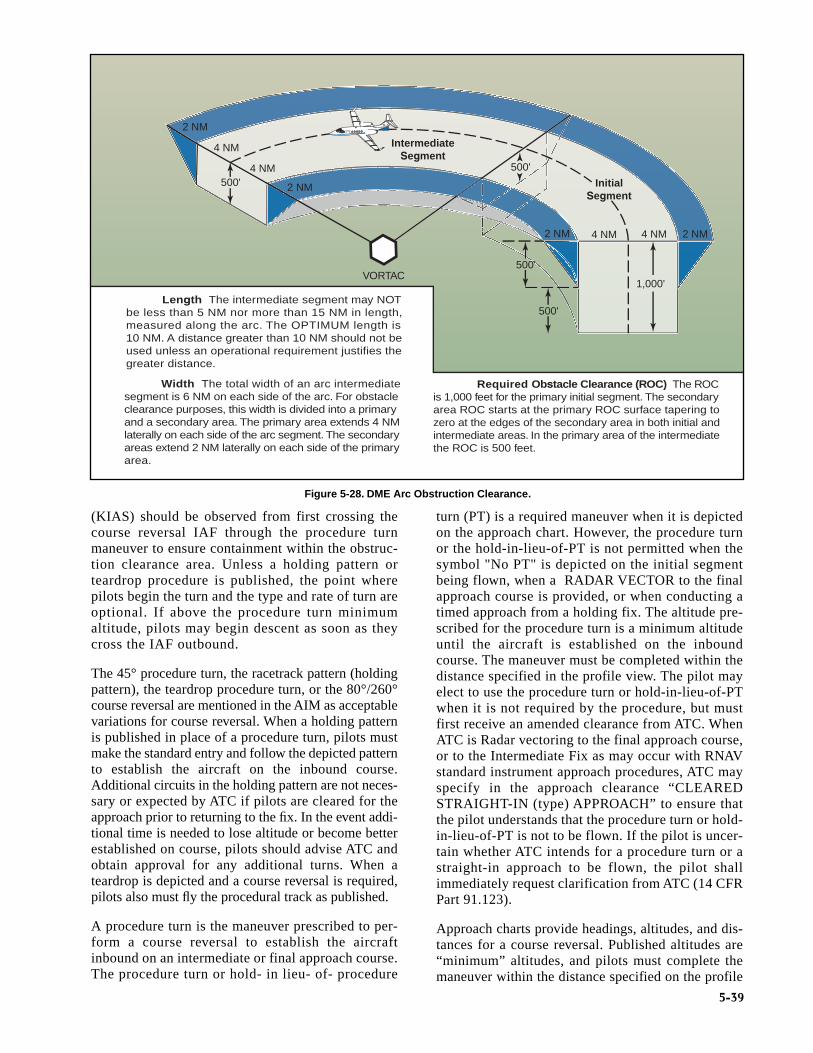
(KIAS) should be observed from first crossing thecourse reversal IAF through the procedure turnmaneuver to ensure containment within the obstruc-tion clearance area. Unless a holding pattern orteardrop procedure is published, the point wherepilots begin the turn and the type and rate of turn areoptional. If above the procedure turn minimumaltitude, pilots may begin descent as soon as theycross the IAF outbound.
The 45° procedure turn, the racetrack pattern (holdingpattern), the teardrop procedure turn, or the 80°/260°course reversal are mentioned in the AIM as acceptablevariations for course reversal. When a holding patternis published in place of a procedure turn, pilots mustmake the standard entry and follow the depicted patternto establish the aircraft on the inbound course.Additional circuits in the holding pattern are not neces-sary or expected by ATC if pilots are cleared for theapproach prior to returning to the fix. In the event addi-tional time is needed to lose altitude or become betterestablished on course, pilots should advise ATC andobtain approval for any additional turns. When ateardrop is depicted and a course reversal is required,pilots also must fly the procedural track as published.
A procedure turn is the maneuver prescribed to per-form a course reversal to establish the aircraftinbound on an intermediate or final approach course.The procedure turn or hold- in lieu- of- procedure
turn (PT) is a required maneuver when it is depictedon the approach chart. However, the procedure turnor the hold-in-lieu-of-PT is not permitted when thesymbol "No PT" is depicted on the initial segmentbeing flown, when a RADAR VECTOR to the finalapproach course is provided, or when conducting atimed approach from a holding fix. The altitude pre-scribed for the procedure turn is a minimum altitudeuntil the aircraft is established on the inboundcourse. The maneuver must be completed within thedistance specified in the profile view. The pilot mayelect to use the procedure turn or hold-in-lieu-of-PTwhen it is not required by the procedure, but mustfirst receive an amended clearance from ATC. WhenATC is Radar vectoring to the final approach course,or to the Intermediate Fix as may occur with RNAVstandard instrument approach procedures, ATC mayspecify in the approach clearance “CLEAREDSTRAIGHT-IN (type) APPROACH” to ensure thatthe pilot understands that the procedure turn or hold-in-lieu-of-PT is not to be flown. If the pilot is uncer-tain whether ATC intends for a procedure turn or astraight-in approach to be flown, the pilot shallimmediately request clarification from ATC (14 CFRPart 91.123).
Approach charts provide headings, altitudes, and dis-tances for a course reversal. Published altitudes are“minimum” altitudes, and pilots must complete themaneuver within the distance specified on the profile
500'
4 NM 4 NM 2 NM2 NM
VORTAC
Length The intermediate segment may NOTbe less than 5 NM nor more than 15 NM in length,measured along the arc. The OPTIMUM length is 10 NM. A distance greater than 10 NM should not beused unless an operational requirement justifies thegreater distance.
Width The total width of an arc intermediatesegment is 6 NM on each side of the arc. For obstacleclearance purposes, this width is divided into a primaryand a secondary area. The primary area extends 4 NMlaterally on each side of the arc segment. The secondaryareas extend 2 NM laterally on each side of the primaryarea.
Required Obstacle Clearance (ROC) The ROCis 1,000 feet for the primary initial segment. The secondary area ROC starts at the primary ROC surface tapering tozero at the edges of the secondary area in both initial andintermediate areas. In the primary area of the intermediatethe ROC is 500 feet.
500'
1,000'
InitialSegment
500'
IntermediateSegment
500'
2 NM
2 NM
4 NM
4 NM
Figure 5-28. DME Arc Obstruction Clearance.
5-39

5-40
view (typically within 10 NM). Pilots also are requiredto maneuver the aircraft on the procedure turn side ofthe final approach course. These requirements arenecessary to stay within the protected airspace andmaintain adequate obstacle clearance. [Figure 5-29]
A minimum of 1,000 feet of obstacle clearance is pro-vided in the procedure turn primary area. [Figure 5-30]In the secondary area, 500 feet of obstacle clearance isprovided at the inner edge, tapering uniformly to zerofeet at the outer edge. The primary and secondary areasdetermine obstacle clearance in both the entry andmaneuvering zones. The use of entry and maneuveringzones provides further relief from obstacles. The entryzone is established to control the obstacle clearanceprior to proceeding outbound from the procedure turnfix. The maneuvering zone is established to controlobstacle clearance after proceeding outbound from theprocedure turn fix.
INITIAL APPROACH SEGMENTThe purpose of the initial approach segment is toprovide a method for aligning the aircraft with theintermediate or final approach segment. This isaccomplished by using a DME arc, a course reversal,such as a procedure turn or holding pattern, or byfollowing a terminal route that intersects the finalapproach course. The initial approach segment
Obstacle
Primary Area
Secondary Area
Entry Zone Maneuvering Zone
1000'
1000'
Altitude restricted until departing IAF outbound.
1,000' Obstacle Clearance
500' — 0' Obstacle Clearance
Figure 5-30. Procedure Turn Obstacle Clearance.
Standard 45° Turn Teardrop Pattern
270°
225°04
5°
090° 270°
Holding/Racetrack Pattern80°/260° Course Reversal
260°090°
170°
Figure 5-29. Course Reversal Methods.

5-41
begins at an IAF and usually ends where it joins theintermediate approach segment or at an IF. The let-ters IAF on an approach chart indicate the loca-tion of an IAF and more than one may be available.Course, distance, and minimum altitudes are also pro-vided for initial approach segments. A given proce-dure may have several initial approach segments.When more than one exists, each joins a commonintermediate segment, although not necessarily at thesame location.
Occasionally, a chart may depict an IAF, although thereis no initial approach segment for the procedure. Thisusually occurs at a point located within the en routestructure where the intermediate segment begins. In thissituation, the IAF signals the beginning of the interme-diate segment.
INTERMEDIATE APPROACH SEGMENTThe intermediate segment is designed primarily to posi-tion the aircraft for the final descent to the airport. Likethe feeder route and initial approach segment, the chartdepiction of the intermediate segment provides course,distance, and minimum altitude information.
The intermediate segment, normally aligned within 30°of the final approach course, begins at the IF, or interme-diate point, and ends at the beginning of the finalapproach segment. In some cases, an IF is not shown on
an approach chart. In this situation, the intermediate seg-ment begins at a point where you are proceedinginbound to the FAF, are properly aligned with the finalapproach course, and are located within the prescribeddistance prior to the FAF. An instrument approach thatincorporates a procedure turn is the most commonexample of an approach that may not have a charted IF.The intermediate segment in this example begins whenyou intercept the inbound course after completing theprocedure turn. [Figure 5-31]
FINAL APPROACH SEGMENTThe final approach segment for an approach with ver-tical guidance or a precision approach begins wherethe glide slope intercepts the minimum glide slopeintercept altitude shown on the approach chart. If ATCauthorizes a lower intercept altitude, the finalapproach segment begins upon glide slope intercep-tion at that altitude. For a nonprecision approach, thefinal approach segment begins either at a designatedFAF, depicted as a cross on the profile view, or at thepoint where the aircraft is established inbound on thefinal approach course. When a FAF is not designated,such as on an approach that incorporates an on-airportVOR or NDB, this point is typically where the pro-cedure turn intersects the final approach courseinbound. This point is referred to as the finalapproach point (FAP). The final approach segmentends at either the designated MAP or upon landing.
FAF
Beginning of Intermediate Segment
IAF
Initial ApproachSegment
Feeder Route
Enroute Fix
Figure 5-31. Approach without a Designated IF.

5-42
There are three types of procedures based on thefinal approach course guidance:
• Precision Approach (PA) — an instrumentapproach based on a navigation system that pro-vides course and glidepath deviation informationmeeting precision standards. Precision ApproachRadar (PAR), ILS, and Microwave LandingSystem (MLS) procedures are examples of PAprocedures.
• Approach with Vertical Guidance (APV) — aninstrument approach based on a navigation sys-tem that is not required to meet the precisionapproach standards but provides course andglidepath deviation information. Baro-VNAV,LDA with glidepath, and LPV are examples ofAPV approaches.
• Nonprecision Approach (NPA) — an instrumentapproach based on a navigation system thatprovides course deviation information but noglidepath deviation information is considered aNPA procedure. VOR, TACAN, LNAV, NDB,LOC and ASR approaches are examples ofNPA procedures.
MISSED APPROACH SEGMENTThe missed approach segment begins at the MAPand ends at a point or fix where an initial or en routesegment begins. The actual location of the MAPdepends upon the type of approach you are flying.For example, during a precision or an APV approach,the MAP occurs at the DA or DH on the glide slope.For nonprecision approaches, the MAP is either afix, NAVAID, or after a specified period of time haselapsed after crossing the FAF.
APPROACH CLEARANCEAccording to FAA Order 7110.65, Air Traffic Control,clearances authorizing instrument approaches areissued on the basis that, if visual contact with theground is made before the approach is completed, theentire approach procedure will be followed unless thepilot receives approval for a contact approach, iscleared for a visual approach, or cancels the IFR flightplan.
Approach clearances are issued based on known traf-fic. The receipt of an approach clearance does notrelieve the pilot of his/her responsibility to complywith applicable Parts of the CFRs and notations oninstrument approach charts, which impose on thepilot the responsibility to comply with or act onan instruction, such as “procedure not authorizedat night.” The name of the approach, as pub-lished, is used to identify the approach. Approachname items within parentheses are not includedin approach clearance phraseology.
VECTORS TO FINAL APPROACH COURSEThe approach gate is an imaginary point used withinATC as a basis for vectoring aircraft to the finalapproach course. The gate will be established along thefinal approach course one mile from the FAF on theside away from the airport and will be no closer than 5NM from the landing threshold. Controllers are alsorequired to ensure the assigned altitude conforms to thefollowing:
• For a precision approach, at an altitude not abovethe glide slope/glidepath or below the minimumglide slope intercept altitude specified on theapproach procedure chart.
• For a nonprecision approach, at an altitude thatwill allow descent in accordance with the pub-lished procedure.
Further, controllers must assign headings that will per-mit final approach course interception without exceed-ing the following:
A typical vector to the final approach course andassociated approach clearance is as follows:
“…four miles from LIMA, turn right headingthree four zero, maintain two thousand until estab-lished on the localizer, cleared ILS runway three sixapproach.”
Other clearance formats may be used to fit individualcircumstances but the controller should alwaysassign an altitude to maintain until the aircraft isestablished on a segment of a published route or IAP.The altitude assigned must guarantee IFR obstruc-tion clearance from the point at which the approachclearance is issued until the aircraft is established ona published route. Part 91.175 (j) prohibits a pilotfrom making a procedure turn when vectored to aFAF or course, when conducting a timed approach,or when the procedure specifies “NO PT.”
When vectoring aircraft to the final approach course,controllers are required to ensure the intercept is atleast 2 NM outside the approach gate. Exceptionsinclude the following situations, but do not apply to
Distance from InterceptionPoint to Approach Gate
MaximumInterception Angle
• Less than 2 NM or withtriple simultaneousILS/MLS approaches inuse.
20°
• 2 NM or more 30°(45°for helicopters)

5-43
RNAV aircraft being vectored for a GPS or RNAVapproach:
• When the reported ceiling is at least 500 feetabove the MVA/MIA and the visibility is at least3 SM (may be a pilot report [PIREP] if noweather is reported for the airport), aircraft maybe vectored to intercept the final approach coursecloser than 2 NM outside the approach gate butno closer than the approach gate.
• If specifically requested by the pilot, aircraftmay be vectored to intercept the finalapproach course inside the approach gate butno closer than the FAF.
NONRADAR ENVIRONMENTIn the absence of radar vectors, an instrumentapproach begins at an IAF. An aircraft that has beencleared to a holding fix that, prior to reaching thatfix, is issued a clearance for an approach, but notissued a revised routing, such as, “proceed directto…” is expected to proceed via the last assignedroute, a feeder route if one is published on theapproach chart, and then to commence the approachas published. If, by following the route of flight tothe holding fix, the aircraft would overfly an IAF orthe fix associated with the beginning of a feederroute to be used, the aircraft is expected to com-mence the approach using the published feeder routeto the IAF or from the IAF as appropriate. The air-craft would not be expected to overfly and return tothe IAF or feeder route.
For aircraft operating on unpublished routes, analtitude is assigned to maintain until the aircraft isestablished on a segment of a published route orIAP. (Example: “maintain 2,000 until establishedon the final approach course outbound, clearedVOR/DME runway 12.”) The International CivilAviation Organization (ICAO) definition of estab-lished on course requires the aircraft to be withinhalf scale deflection for the ILS and VOR, orwithin ±5° of the required bearing for the NDB.Generally, the controller assigns an altitude compati-ble with glide slope intercept prior to being clearedfor the approach.
TYPES OF APPROACHESIn the NAS, there are approximately 1,033 VOR sta-tions, 1,200 NDB stations, and 1,370 ILS installations,including 25 LOC-Type Directional Aids (LDAs), 23Simplified Directional Facilities (SDFs), and 242 LOConly facilities. As time progresses, it is the intent of theFAA to reduce navigational dependence on VOR,NDB, and other ground-based NAVAIDs and, instead,to increase the use of satellite-based navigation.
To expedite the use of RNAV procedures for all instru-ment pilots, the FAA has begun an aggressive schedule
to develop RNAV procedures. During 2002, the numberof RNAV/GPS approaches published in the NASexceeded 3,300, with additional procedures publishedevery revision cycle. While it had originally been theplan of the FAA to begin decommissioning VORs,NDBs, and other ground-based NAVAIDs, the overallstrategy has been changed to incorporate a majoritydependence on augmented satellite navigation whilemaintaining a satisfactory backup system. Thisbackup system will include retaining all CAT II andIII ILS facilities and close to one-half of the existingVOR network.
Each approach is provided obstacle clearance based onthe Order 8260.3 TERPS design criteria as appropriatefor the surrounding terrain, obstacles, and NAVAIDavailability. Final approach obstacle clearance is differ-ent for every type of approach but is guaranteed fromthe start of the final approach segment to the runway (notbelow the MDA for nonprecision approaches) or MAP,whichever occurs last within the final approach area.Both pilots and ATC assume obstacle clearance respon-sibility, but it is dependent upon the pilot to maintain anappropriate flight path within the boundaries of the finalapproach area.
There are numerous types of instrument approachesavailable for use in the NAS including RNAV (GPS),ILS, MLS, LOC, VOR, NDB, SDF, and radarapproaches. Each approach has separate and individualdesign criteria, equipment requirements, and systemcapabilities.
VISUAL AND CONTACT APPROACHESTo expedite traffic, ATC may clear pilots for a visualapproach in lieu of the published approach procedure ifflight conditions permit. Requesting a contactapproach may be advantageous since it requires lesstime than the published IAP and provides separationfrom IFR and special visual flight rules (SVFR) traffic.A contact or visual approach may be used in lieu of con-ducting a SIAP, and both allow the flight to continue asan IFR flight to landing while increasing the efficiencyof the arrival.
VISUAL APPROACHESWhen it is operationally beneficial, ATC may authorizepilots to conduct a visual approach to the airport in lieuof the published IAP. A pilot or the controller can initi-ate a visual approach. Before issuing a visual approachclearance, the controller must verify that pilots havethe airport, or a preceding aircraft that they are to fol-low, in sight. In the event pilots have the airport in sightbut do not see the aircraft they are to follow, ATC mayissue the visual approach clearance but will maintainresponsibility for aircraft and wake turbulence separa-tion. Once pilots report the aircraft in sight, they

5-44
assume the responsibilities for their own separationand wake turbulence avoidance.
A visual approach is an ATC authorization for anaircraft on an IFR flight plan to proceed visuallyto the airport of intended landing; it is not an IAP.Also, there is no missed approach segment. An air-craft unable to complete a visual approach mustbe handled as any other go-around and appropriateseparation must be provided. A vector for a visualapproach may be initiated by ATC if the reportedceiling at the airport of intended landing is at least500 feet above the MVA/MIA and the visibility is3 SM or greater. At airports without weather report-ing service there must be reasonable assurance (e.g.area weather reports, PIREPs, etc.) that descent andapproach to the airport can be made visually, and thepilot must be informed that weather information isnot available.
The visual approach clearance is issued to expedite theflow of traffic to an airport. It is authorized when theceiling is reported or expected to be at least 1,000 feetAGL and the visibility is at least 3 SM. Pilots mustremain clear of the clouds at all times while conductinga visual approach. At an airport with a control tower,pilots may be cleared to fly a visual approach to onerunway while others are conducting VFR or IFRapproaches to another parallel, intersecting, or converg-ing runway. Also, when radar service is provided, it isautomatically terminated when the controller advisespilots to change to the tower or advisory frequency.
CONTACT APPROACHESIf conditions permit, pilots can request a contactapproach, which is then authorized by the controller. Acontact approach cannot be initiated by ATC. This pro-cedure may be used instead of the published procedureto expedite arrival, as long as the airport has a SIAP orspecial instrument approach procedure (special IAPsare approved by the FAA for individual operators, butare not published in Part 97 for public use), the reportedground visibility is at least 1 SM, and pilots are able toremain clear of clouds with at least one statute mile flightvisibility throughout the approach. Some advantages ofa contact approach are that it usually requires less timethan the published instrument procedure, it allows pilotsto retain the IFR clearance, and provides separation fromIFR and SVFR traffic. On the other hand, obstructionclearances and VFR traffic avoidance becomes thepilot’s responsibility. Unless otherwise restricted, thepilot may find it necessary to descend, climb, or fly acircuitous route to the airport to maintain cloudclearance or terrain/obstruction clearance.
The main differences between a visual approach and acontact approach are: a pilot must request a contact
approach, while a visual approach may be assigned byATC or requested by the pilot; and, a contact approachmay be approved with 1 mile visibility if the flight canremain clear of clouds, while a visual approach requiresthe pilot to have the airport in sight, or a preceding air-craft to be followed, and the ceiling must be at least1,000 feet AGL with at least 3 SM visibility.
CHARTED VISUAL FLIGHT PROCEDURESA charted visual flight procedure (CVFP) may beestablished at some airports with control towers forenvironmental or noise considerations, as well aswhen necessary for the safety and efficiency of air traf-fic operations. Designed primarily for turbojet aircraft,CVFPs depict prominent landmarks, courses, and rec-ommended altitudes to specific runways. When pilotsare flying the Roaring Fork Visual RWY 15 shown infigure 5-32, mountains, rivers, and towns provideguidance to Aspen, Colorado’s Sardy Field insteadof VORs, NDBs, and DME fixes.
Pilots must have a charted visual landmark or a preced-ing aircraft in sight, and weather must be at or above thepublished minimums before ATC will issue a CVFPclearance. ATC will clear pilots for a CVFP if thereported ceiling at the airport of intended landing is atleast 500 feet above the MVA/MIA, and the visibility is3 SM or more, unless higher minimums are publishedfor the particular CVFP. When accepting a clearance tofollow a preceding aircraft, pilots are responsible formaintaining a safe approach interval and wake turbu-lence separation. Pilots must advise ATC if unable at anypoint to continue a charted visual approach or if the pilotloses sight of the preceding aircraft.
RNAV APPROACHESBecause of the complications with database coding,naming conventions were changed in January 2001 toaccommodate all approaches using RNAV equipmentinto one classification — RNAV. This classificationincludes both ground-based and satellite dependentsystems. Eventually all approaches that use some typeof RNAV will reflect RNAV in the approach title. Thischangeover is being made to reflect two shifts ininstrument approach technology. The first shift is theuse of the RNP concept outlined in Chapter 2 —Departure Procedures, in which a single performancestandard concept is being implemented for approachprocedure design. Through the use of RNP, the under-lying system of navigation may not be required, pro-vided the aircraft can maintain the appropriate RNPstandard. The second shift is that advanced avionicssystems such as FMSs, used by most airlines, needed anew navigation standard by which RNAV could befully integrated into the instrument approach system.An FMS uses multi-sensor navigation inputs to pro-duce a composite position. Essentially, the FMS navi-gation function automatically blends or selects position

5-45
sensors to compute aircraft position. Instrumentapproach charts and RNAV databases needed to changeto reflect these issues. A complete discussion of air-borne navigation databases is included in Appendix A— Airborne Navigation Databases.
Due to the multi-faceted nature of RNAV, newapproach criteria have been developed to accommo-date the design of RNAV instrument approaches.This includes criteria for TAAs, RNAV basicapproach criteria, and specific final approach criteriafor different types of RNAV approaches.
TERMINAL ARRIVAL AREASTAAs are the method by which aircraft are transitionedfrom the RNAV en route structure to the terminal areawith minimal ATC interaction. Terminal arrival areas
are depicted in the planview of the approach chart, andeach waypoint associated with them is also providedwith a unique five character, pronounceable name. TheTAA consists of a designated volume of airspacedesigned to allow aircraft to enter a protected area,offering guaranteed obstacle clearance where the initialapproach course is intercepted based on the location ofthe aircraft relative to the airport. Where possible,TAAs are developed as a basic “T” shape that is dividedinto three separate arrival areas around the head of the“T”: left base, right base, and straight-in. Typically, theTAA offers an IAF at each of these three arrival areasthat are 3-6 NM from an IF, which often doubles as theIAF for straight-in approaches, a FAF located approxi-mately 5 NM from the runway threshold, and a MAP.[Figure 5-33 on page 5-46]
Figure 5-32. Charted Visual Flight Procedures.

5-46
Procedurally, pilots may be cleared to an IAF associ-ated with the TAA. ATC expects the flight to proceed tothe IAF and maintain the altitude depicted for that areaof the TAA, unless cleared otherwise. An obstacleclearance of at least 1,000 feet is guaranteed within theboundaries of the TAA.
TAAs are modified or even eliminated if necessary tomeet the requirements of a specific airport and sur-rounding terrain, or airspace considerations negatingthe use of the “T” approach design concept. Alternativedesigns are addressed in FAA Order 8260.45A,Terminal Arrival Area (TAA) Design Criteria.Variations may eliminate one or both base areas, and/orlimit or modify the angular size of the straight-in area.When both base areas are eliminated, TAAs are notdepicted in the planview. Normally, a portion of theTAA underlies an airway. If this is not the case, at leastone feeder route is provided from an airway fix orNAVAID to the TAA boundary. The feeder route pro-vides a direct course from the en route fix/NAVAID to
the appropriate IF/IAF. Multiple feeder routes may alsobe established. In some cases, TAAs may not bedepicted because of airspace congestion or otheroperational requirements. [Figure 5-34]
RNAV FINAL APPROACH DESIGN CRITERIARNAV encompasses a variety of underlying navigationsystems and, therefore, approach criteria. This resultsin different sets of criteria for the final approach seg-ment of various RNAV approaches. RNAV instrumentapproach criteria address the following procedures:
• GPS overlay of pre-existing nonprecisionapproaches.
• VOR/DME based RNAV approaches.
• Stand-alone RNAV (GPS) approaches.
• RNAV (GPS) approaches with vertical guidance(APV).
• RNAV (GPS) precision approaches (WAAS andLAAS).
Figure 5-33.Terminal Arrival Area Design (Basic “T”).

5-47
Figure 5-34. RNAV Approaches with and without TAAs.

5-48
GPS OVERLAY OF NONPRECISION APPROACHThe original GPS approach procedures providedauthorization to fly nonprecision approaches based onconventional, ground-based NAVAIDs. Many of theseapproaches have been converted to stand-aloneapproaches, and the few that remain are identified bythe name of the procedure and “or GPS.” These GPSnonprecision approaches are predicated upon thedesign criteria of the ground-based NAVAID used asthe basis of the approach. As such, they do not adhereto the RNAV design criteria for stand-alone GPSapproaches, and are not considered part of the RNAV(GPS) approach classification for determining designcriteria. [Figure 5-35]
GPS STAND-ALONE/RNAV (GPS) APPROACHRNAV (GPS) approaches are named so that airbornenavigation databases can use either GPS or RNAV asthe title of the approach. This is required for non-GPSapproach systems such as VOR/DME based RNAVsystems. In the past, these approaches were oftenreferred to as stand-alone GPSs. They are considerednonprecision approaches, offering only LNAV andcircling minimums. Precision minimums are notauthorized, although LNAV/VNAV minimums maybe published and used as long as the on-board systemis capable of providing approach approved VNAV.The RNAV (GPS) Runway 18 approach forAlexandria, Louisiana incorporates only LNAV andcircling minimums. [Figure 5-36]
Figure 5-35.Traditional GPS Overlay Approach.

5-49
For a non-vertically guided straight-in RNAV (GPS)approach, the final approach course must be alignedwithin 15° of the extended runway centerline. The finalapproach segment should not exceed 10 NM, and whenit exceeds 6 NM, a stepdown fix is typically incorpo-rated. A minimum of 250 feet obstacle clearance is alsoincorporated into the final approach segment forstraight-in approaches, and a maximum 400-foot perNM descent gradient is permitted.
The approach design criteria are different forapproaches that use vertical guidance provided by aBaro-VNAV system. Because the Baro-VNAV guid-ance is advisory and not primary, Baro-VNAVapproaches are not authorized in areas of hazardous ter-
rain, nor are they authorized when a remote altimetersetting is required. Due to the inherent problems asso-ciated with barometric readings and cold temperatures,these procedures are also temperature limited.Additional approach design criteria for RNAVApproach Construction Criteria can be found in theappropriate Order 8260 series directives.
RNAV (GPS) APPROACH USING WAASWAAS was commissioned in July, 2003, with initialoperational capability (IOC). Although precisionapproach capability is still in the future, initial WAAScurrently provides a new type of approach with verticalguidance (APV) known as LPV. Approach minimums aslow as 200 feet HAT and 1/2 SM visibility are possible,
Figure 5-36. Alexandria International (KAEX), Alexandria, Louisiana, RNAV (GPS) RWY 18.

5-50
even though LPV is semi-precision, and not considereda precision approach. WAAS covers 95 percent of thecountry 95 percent of the time.
NOTE: WAAS avionics receive an airworthinessapproval in accordance with Technical Standard Order(TSO) C-145A, Airborne Navigation Sensors Usingthe (GPS) Augmented by the Wide Area AugmentationSystem (WAAS), or TSO-146A, Stand-Alone AirborneNavigation Equipment Using the Global PositioningSystem (GPS) Augmented by the Wide AreaAugmentation System (WAAS), and installed inaccordance with AC 20-130A, AirworthinessApproval of Navigation or Flight ManagementSystems Integrating Multiple Navigation Sensors, orAC 20-138A, Airworthiness Approval of GlobalPositioning System (GPS) Navigation Equipment forUse as a VFR and IFR Navigation System.
Precision approach capability will become availablewhen LAAS becomes operational. LAAS furtherincreases the accuracy of GPS and improves signalintegrity warnings. Precision approach capabilityrequires obstruction planes and approach lighting sys-tems to meet Part 77 standards for ILS approaches.This will delay the implementation of RNAV (GPS)precision approach capability due to the cost of certi-fying each runway.
ILS APPROACHESNotwithstanding emerging RNAV technology, the ILSis the most precise and accurate approach NAVAIDcurrently in use throughout the NAS. An ILS CAT Iprecision approach allows approaches to be made to200 feet above the TDZE and with visibilities as lowas 1,800 RVR; with CAT II and CAT III approachesallowing descents and visibility minimums that areeven lower. Nonprecision approach alternatives cannotbegin to offer the precision or flexibility offered by anILS. In order to further increase the approach capacityof busy airports and exploit the maximum potential ofILS technology, many different applications are in use.
A single ILS system can accommodate 29 arrivalsper hour on a single runway. Two or three parallelrunways operating consecutively can double or triplethe capacity of the airport. For air commerce thismeans greater flexibility in scheduling passengerand cargo service. Capacity is increased through theuse of parallel (dependent) ILS, simultaneous paral-lel (independent) ILS, simultaneous close parallel(independent) ILS, precision runway monitor(PRM), and converging ILS approaches. A parallel(dependent) approach differs from a simultaneous(independent) approach in that the minimum distancebetween parallel runway centerlines is reduced; there isno requirement for radar monitoring or advisories; and a
staggered separation of aircraft on the adjacentlocalizer/azimuth course is required.
In order to successfully accomplish parallel,simultaneous parallel, and converging ILSapproaches, flight crews and air traffic controllershave additional responsibilities. When multipleinstrument approaches are in use, ATC will adviseflight crews either directly or through ATIS. It isthe pilot’s responsibility to inform ATC if unable orunwilling to execute a simultaneous approach.Pilots must comply with all ATC requests in atimely manner, and maintain strict radio discipline,including using complete aircraft call signs. It isalso incumbent upon the flight crew to notify ATCimmediately of any problems relating to aircraftcommunications or navigation systems. At the veryleast, the approach procedure briefing should coverthe entire approach procedure including theapproach name, runway number, frequencies, finalapproach course, glide slope intercept altitude, DAor DH, and the missed approach instructions. Thereview of autopilot procedures is also appropriatewhen making coupled ILS or MLS approaches.
As with all approaches, the primary navigationresponsibility falls upon the pilot in command. ATCinstructions will be limited to ensuring aircraft sepa-ration. Additionally, missed approach procedures arenormally designed to diverge in order to protect allinvolved aircraft. ILS approaches of all types areafforded the same obstacle clearance protection anddesign criteria, no matter how capacity is affected bymultiple ILS approaches. [Figure 5-37]
ILS APPROACH CATEGORIESThere are three general classifications of ILSapproaches — CAT I, CAT II, and CAT III (autoland).The basic ILS approach is a CAT I approach andrequires only that pilots be instrument rated and cur-rent, and that the aircraft be equipped appropriately.CAT II and CAT III ILS approaches typically havelower minimums and require special certification foroperators, pilots, aircraft, and airborne/groundequipment. Because of the complexity and high costof the equipment, CAT III ILS approaches are usedprimarily in air carrier and military operations.[Figure 5-38]
CAT II AND III APPROACHESThe primary authorization and minimum RVRsallowed for an air carrier to conduct CAT II and IIIapproaches can be found in OpsSpecs – Part C. CAT IIand III operations allow authorized pilots to makeinstrument approaches in weather that would otherwisebe prohibitive.
While CAT I ILS operations permit substitution ofmidfield RVR for TDZ RVR (when TDZ RVR is not

5-51
available), CAT II ILS operations do not permit anysubstitutions for TDZ RVR. The touchdown zone
RVR system is required and must be used. Touchdownzone RVR is controlling for all CAT II ILS operations.
200 Feet Current andPrevious
ILS Final Approach Criteria (for Primary Protected Airspace)
Final Approach Area
50,200 Feet Current50,000 Feet Previous
1,400 Feet Current1,000 Feet Previous
12,152 Feet Current16,000 Feet Previous
Figure 5-37. ILS Final Approach Segment Design Criteria.
200
100
0 150 700 1,200 1,800 2,400
CAT II
CAT I
CAT III c
CAT III b
CAT III aRunway Visual Range (feet)
Dec
isio
n H
eigh
t (fe
et A
GL)
Photo Courtesy of Cessna
The lowest authorized ILS minimums, with all required ground and airborne systems components operative, are
• CAT I — Decision Height (DH) 200 feet and Runway Visual Range (RVR) 2,400 feet (with touchdown
zone and centerline lighting, RVR 1800 feet),
• CAT II — DH 100 feet and RVR 1,200 feet,
• CAT IIIa — No DH or DH below 100 feet and RVR not less than 700 feet,
• CAT IIIb — No DH or DH below 50 feet and RVR less than 700 feet but not less than 150 feet, and
• CAT IIIc — No DH and no RVR limitation.
NOTE: Special authorization and equipment are required for CAT II and III.
Figure 5-38. ILS Approach Categories.

5-52
The weather conditions encountered in CAT III opera-tions range from an area where visual references areadequate for manual rollout in CAT IIIa, to an areawhere visual references are inadequate even for taxioperations in CAT IIIc. To date, no U.S. operator hasreceived approval for CAT IIIc in OpsSpecs.Depending on the auto-flight systems, some airplanesrequire a DH to ensure that the airplane is going to landin the touchdown zone and some require an AlertHeight as a final crosscheck of the performance of theauto-flight systems. These heights are based on radioaltitude (RA) and can be found in the specific aircraft’sAFM. [Figure 5-39]
Both CAT II and III approaches require special groundand airborne equipment to be installed and operational,as well as special aircrew training and authorization.The OpsSpecs of individual air carriers detail therequirements of these types of approaches as well astheir performance criteria. Lists of locations whereeach operator is approved to conduct CAT II and IIIapproaches can also be found in the OpsSpecs.
ILS APPROACHES TO PARALLEL RUNWAYSAirports that have two or three parallel runways maybe authorized to use parallel approaches to maximizethe capacity of the airport. There are three classifica-tions of parallel ILS approaches, depending on therunway centerline separation and ATC procedures.
PARALLELParallel (dependent) ILS approaches are allowed atairports with parallel runways that have centerlines
separated by at least 2,500 feet. Aircraft are allowedto fly ILS approaches to parallel runways; however,the aircraft must be staggered by a minimum of 1 1/2NM diagonally. Aircraft are staggered by 2 NMdiagonally for runway centerlines that are separatedby more than 4,300 feet and up to but not including9,000 feet, and that do not have final monitor airtraffic controllers. Separation for this type ofapproach is provided by radar. [Figure 5-40]
Though this type of approach procedure is approvedfor several airports, it is not required that the approachchart contain information notifying flight crews of theuse of parallel approaches. Therefore, a pilot may notknow that parallel approaches are approved or used at aspecific airport based on the information contained onthe chart. ATC normally communicates an advisoryover ATIS that parallel approach procedures are ineffect. For example, pilots flying into Sacramento,California may encounter parallel approach proce-dures. [Figure 5-41]
SIMULTANEOUSSimultaneous parallel ILS approaches are used atauthorized airports that have between 4,300 feet and9,000 feet separation between runway centerlines. Adedicated final monitor controller is required tomonitor separation for this type of approach, whichFigure 5-39. Category III Approach Procedure.
Dependent Parallel ILS Approaches
2,500'or
Greater
Staggered Separation
11/2 MilesMinimum
Separation
Figure 5-40. Parallel (Dependent) ILS Approach SeparationCriteria.

5-53
eliminates the need for staggered approaches. Finalmonitor controllers track aircraft positions and issueinstructions to pilots of aircraft observed deviatingfrom the LOC course. [Figure 5-42]
Triple simultaneous approaches are authorizedprovided the runway centerlines are separated byat least 5,000 feet and are below 1,000 feet MSLairport elevation. Additionally, for triple parallelapproaches above airport elevations of 1,000 feetMSL, ASR with high-resolution final monitor aidsor high update RADAR with associated final mon-itor aids is required.
As a part of the simultaneous parallel approachapproval, normal operating zones and non-trans-gression zones must be established to ensure properflight track boundaries for all aircraft. The normaloperating zone (NOZ) is the operating zone withinwhich aircraft remain during normal approachoperations. The NOZ is typically no less than 1,400feet wide, with 700 feet of space on either side ofthe runway centerline. A no transgression zone(NTZ) is a 2,000-foot wide area located betweenthe parallel runway final approach courses. It isequidistant between the runways and indicates anarea within which flight is not authorized. [Figure
5-43 on page 5-54] Any time an aircraft breaches theNTZ, ATC issues instructions for all aircraft to breakoff the approach to avoid potential conflict.
PRECISION RUNWAY MONITORSimultaneous close parallel (independent) ILS PRMapproaches are authorized for use at airports that haveparallel runways separated by at least 3,400 feet and nomore than 4,300 feet. [Figure 5-44 on page 5-54] Theyare also approved for airports with parallel runways sep-arated by at least 3,000 feet with an offset LOC wherethe offset angle is at least 2.5 degrees but no morethan 3 degrees. The offset LOC approaches arereferred to as Simultaneous Offset InstrumentApproaches (SOIA) and are discussed in depth laterin this chapter.
The PRM system provides the ability to accomplishsimultaneous close parallel (independent) ILSapproaches and enables reduced delays and fuelsavings during reduced visibility operations. It is alsothe safest method of increasing ILS capacity throughthe use of parallel approaches. The PRM systemincorporates high-update radar with one second orbetter update time and a high resolution ATC radar
Figure 5-42. Charlotte/Douglas International (KCLT),Charlotte, North Carolina, ILS RWY 18.
Figure 5-41. Sacramento International (KSMF), Sacramento,California, ILS RWY 16L.
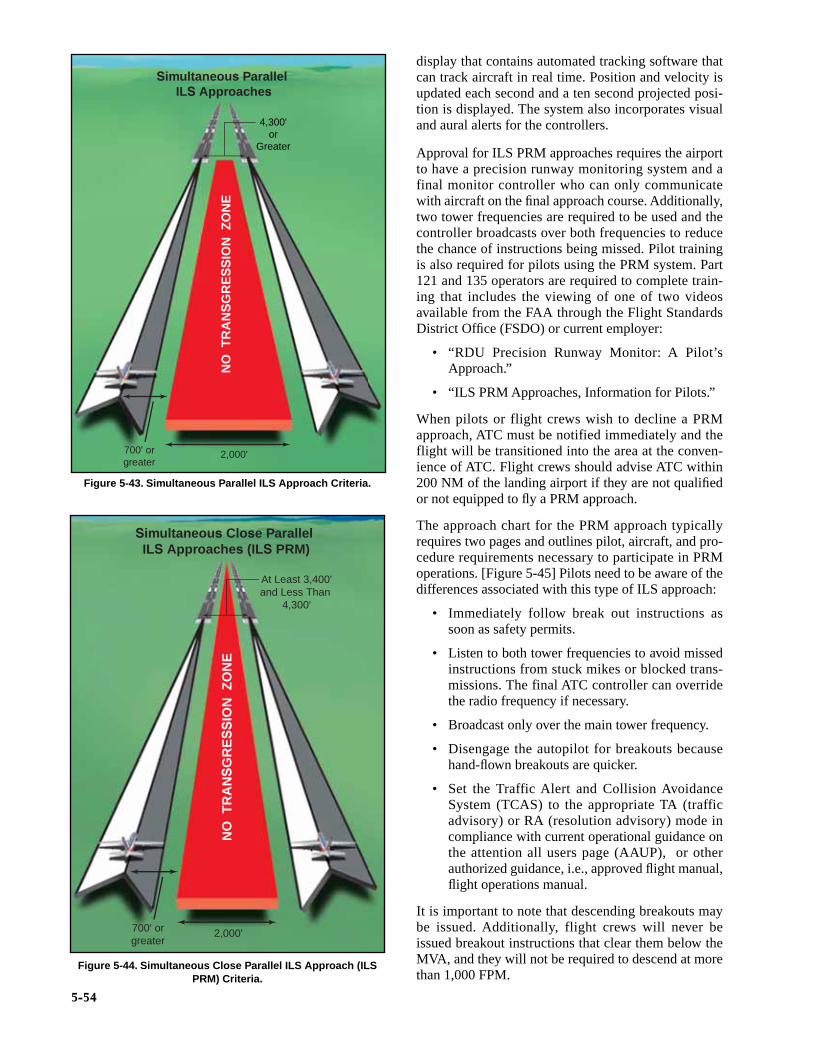
5-54
display that contains automated tracking software thatcan track aircraft in real time. Position and velocity isupdated each second and a ten second projected posi-tion is displayed. The system also incorporates visualand aural alerts for the controllers.
Approval for ILS PRM approaches requires the airportto have a precision runway monitoring system and afinal monitor controller who can only communicatewith aircraft on the final approach course. Additionally,two tower frequencies are required to be used and thecontroller broadcasts over both frequencies to reducethe chance of instructions being missed. Pilot trainingis also required for pilots using the PRM system. Part121 and 135 operators are required to complete train-ing that includes the viewing of one of two videosavailable from the FAA through the Flight StandardsDistrict Office (FSDO) or current employer:
• “RDU Precision Runway Monitor: A Pilot’sApproach.”
• “ILS PRM Approaches, Information for Pilots.”
When pilots or flight crews wish to decline a PRMapproach, ATC must be notified immediately and theflight will be transitioned into the area at the conven-ience of ATC. Flight crews should advise ATC within200 NM of the landing airport if they are not qualifiedor not equipped to fly a PRM approach.
The approach chart for the PRM approach typicallyrequires two pages and outlines pilot, aircraft, and pro-cedure requirements necessary to participate in PRMoperations. [Figure 5-45] Pilots need to be aware of thedifferences associated with this type of ILS approach:
• Immediately follow break out instructions assoon as safety permits.
• Listen to both tower frequencies to avoid missedinstructions from stuck mikes or blocked trans-missions. The final ATC controller can overridethe radio frequency if necessary.
• Broadcast only over the main tower frequency.
• Disengage the autopilot for breakouts becausehand-flown breakouts are quicker.
• Set the Traffic Alert and Collision AvoidanceSystem (TCAS) to the appropriate TA (trafficadvisory) or RA (resolution advisory) mode incompliance with current operational guidance onthe attention all users page (AAUP), or otherauthorized guidance, i.e., approved flight manual,flight operations manual.
It is important to note that descending breakouts maybe issued. Additionally, flight crews will never beissued breakout instructions that clear them below theMVA, and they will not be required to descend at morethan 1,000 FPM.
Simultaneous Parallel ILS Approaches
4,300'or
Greater
NO
TR
AN
SG
RE
SS
ION
ZO
NE
2,000'700' orgreater
Figure 5-43. Simultaneous Parallel ILS Approach Criteria.
Simultaneous Close Parallel ILS Approaches (ILS PRM)
NO
TR
AN
SG
RE
SS
ION
ZO
NE
At Least 3,400'and Less Than
4,300'
2,000'700' orgreater
Figure 5-44. Simultaneous Close Parallel ILS Approach (ILSPRM) Criteria.

5-55
Figure 5-45. St. Louis, Missouri, ILS PRM RWY 11.

5-56
SIMULTANEOUS OFFSET INSTRUMENTAPPROACHESSOIAs allow simultaneous approaches to two parallelrunways spaced at least 750 feet apart, but less than3,000 feet. The SOIA procedure utilizes an ILS/PRMapproach to one runway and an offset Localizer-TypeDirectional Aid (LDA)/PRM approach with glideslope to the adjacent runway. The use of PRM tech-nology is also required with these operations; there-fore, the approach charts will include proceduralnotes such as “Simultaneous approach authorizedwith LDA PRM RWY XXX.” San Francisco has thefirst published SOIA approach. [Figure 5-46]
The training, procedures, and system requirements forSOIA ILS/PRM and LDA/PRM approaches are iden-tical with those used for simultaneous close parallelILS/PRM approaches until near the LDA/PRMapproach MAP, except where visual acquisition of theILS aircraft by the LDA aircraft must be accom-plished. If visual acquisition is not accomplished amissed approach must be executed. A visual segmentfor the LDA/PRM approach is established betweenthe LDA MAP and the runway threshold. Aircrafttransition in visual conditions from the LDA course,beginning at the LDA MAP, to align with the runwayand can be stabilized by 500 feet above ground level(AGL) on the extended runway centerline.
The FAA website has additional information aboutPRM and SOIA, including instructional videos at:http://www.faa.gov/education_research/training/prm/
CONVERGINGAnother method by which ILS approach capacity canbe increased is through the use of convergingapproaches. Converging approaches may be estab-lished at airports that have runways with an anglebetween 15 and 100 degrees and each runway musthave an ILS. Additionally, separate procedures must beestablished for each approach and each approach musthave a MAP at least 3 NM apart with no overlapping ofthe protected missed approach airspace. Only straight-in approaches are approved for converging ILS proce-dures. If the runways intersect, the controller must beable to visually separate intersecting runway traffic.Approaches to intersecting runways also have higherminimums with a 700-foot minimum and no less than 2SM visibility. Pilots are informed of the use of converg-ing ILS approaches by the controller upon initial con-tact or through ATIS. [Figure 5-47 on page 5-58]
Dallas/Fort Worth International airport is one of the fewairports that makes use of converging ILS approachesbecause its runway configuration has multiple parallelrunways and two offset runways. [Figure 5-48 on page5-58] The approach chart title indicates the use of con-
verging approaches and the notes section highlightsother runways that are authorized for convergingapproach procedures.
MICROWAVE LANDING SYSTEMThe MLS is a precision instrument approach alterna-tive to the ILS. It provides azimuth, elevation, and dis-tance information, as well as a back azimuth capable ofproviding guidance for missed approach proceduresand departures. In addition to straight-in approaches,the MLS system can also provide three-dimensionalRNAV type approaches in both computed straight andcurved paths. It was initially designed to replace theILS system and it provided inherent flexibility andbroader reception range with the greatest limitationbeing the capabilities of the airborne equipmentinstalled in individual aircraft.
The MLS has multiple advantages including anincreased number of frequencies, compact groundequipment, and complex approach paths. For a varietyof reasons, particularly the advent of civil use GPS,MLS installation was deferred, and by 1994 it was offi-cially cancelled by the FAA. Today there are few MLSinstallations in the U.S. and currently there are no plansfor further installations. Futhermore, the MLSequipment required for an MLS approach was notwidely installed in aircraft, whereas most newaircraft produced today come with GPS systems.With the limited number of MLS installationsaround the country, it is highly unlikely that mostpilots will ever encounter the MLS approach, andif they do, it is even less likely that the properequipment would be installed in the aircraft.
Like the ILS, the basic MLS approach requires thefinal approach course alignment to be within 3degrees of the extended runway centerline. This typeof approach uses a glide slope between 3 and 6.40degrees and provides precision landing minimums to200 feet HAT. Obstacle clearance is based on the glideslope angle used in the approach design. The designcriteria differ for each type of MLS approach andincorporate numerous formulas for the derivation ofspecific course criteria. This information is containedin FAA Order 8260.3 Volume 3, Chapters 2 and 3.
In the front of the TPP, there is a page containing addi-tional information pertaining to the use of an MLS sys-tem. The MLS Channeling and Frequency PairingTable cross references the appropriate MLS channelwith its paired VHF and TACAN frequencies. Groundequipment associated with the MLS operates on theMLS channels, while the MLS angle/data and DME isrequired to operate using one of the paired VHF orTACAN frequencies.

5-57
Figure 5-46. Simultaneous Offset Instrument Approach Procedure.

5-58
15° to100°
Figure 5-47. Converging Approach Criteria.
Figure 5-48. Dallas/Fort Worth (KDFW), Dallas/Fort Worth,Texas, CONVERGING ILS RWY 35C.

5-59
VOR APPROACH The VOR is one of the most widely used nonprecisionapproach types in the NAS. VOR approaches use VORfacilities both on and off the airport to establishapproaches and include the use of a wide variety ofequipment such as DME and TACAN. Due to the widevariety of options included in a VOR approach, TERPSoutlines design criteria for both on and off airport VORfacilities as well as VOR approaches with and withouta FAF. Despite the various configurations, all VORapproaches are nonprecision approaches, require thepresence of properly operating VOR equipment, andcan provide MDAs as low as 250 feet above the run-way. VOR also offers a flexible advantage in that anapproach can be made toward or away from thenavigational facility.
The VOR approach into Missoula International inMissoula, Montana, is an example of a VOR approachwhere the VOR facility is on the airport and there is nospecified FAF. [Figure 5-49] For a straight-in approach,the final approach course is typically aligned to intersectthe extended runway centerline 3,000 feet from the run-way threshold, and the angle of convergence betweenthe two does not exceed 30 degrees. This type of VOR
approach also includes a minimum of 300 feet of obstacleclearance in the final approach area. The final approacharea criteria include a 2 NM wide primary area at thefacility that expands to 6 NM wide at a distance of 10 NMfrom the facility. Additional approach criteria are estab-lished for courses that require a high altitude teardropapproach penetration.
When DME is included in the title of the VORapproach, operable DME must be installed in the air-craft in order to fly the approach from the FAF. Theuse of DME allows for an accurate determination ofposition without timing, which greatly increases situa-tional awareness throughout the approach. Alexandria,Louisiana, is an excellent example of a VOR/DMEapproach in which the VOR is off the airport and a FAFis depicted. [Figure 5-50 on page 5-60] In this case,the final approach course is a radial or straight-in finalapproach and is designed to intersect the runway center-line at the runway threshold with the angle of conver-gence not exceeding 30 degrees.
The criteria for an arc final approach segment associatedwith a VOR/DME approach is based on the arc beingbeyond 7 NM and no farther than 30 NM from the VOR,
Figure 5-49. Missoula International, Missoula, Montana (KMSO), VOR–C.
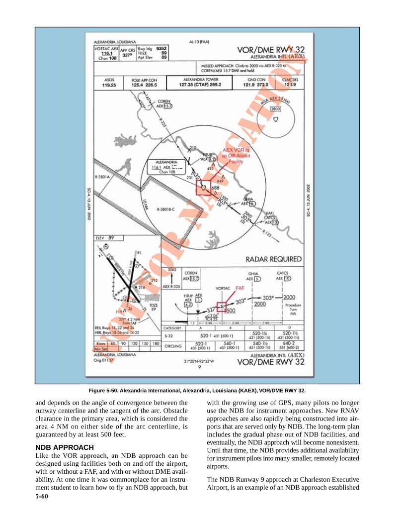
and depends on the angle of convergence between therunway centerline and the tangent of the arc. Obstacleclearance in the primary area, which is considered thearea 4 NM on either side of the arc centerline, isguaranteed by at least 500 feet.
NDB APPROACHLike the VOR approach, an NDB approach can bedesigned using facilities both on and off the airport,with or without a FAF, and with or without DME avail-ability. At one time it was commonplace for an instru-ment student to learn how to fly an NDB approach, but
with the growing use of GPS, many pilots no longeruse the NDB for instrument approaches. New RNAVapproaches are also rapidly being constructed into air-ports that are served only by NDB. The long-term planincludes the gradual phase out of NDB facilities, andeventually, the NDB approach will become nonexistent.Until that time, the NDB provides additional availabilityfor instrument pilots into many smaller, remotely locatedairports.
The NDB Runway 9 approach at Charleston ExecutiveAirport, is an example of an NDB approach established
5-60
Figure 5-50. Alexandria International, Alexandria, Louisiana (KAEX), VOR/DME RWY 32.

5-61
with an on-airport NDB that does not incorporate aFAF. [Figure 5-51] In this case, a procedure turn orpenetration turn is required to be a part of the approachdesign. For the NDB to be considered an on-airportfacility, the facility must be located within one mile ofany portion of the landing runway for straight-inapproaches and within one mile of any portion ofusable landing surface for circling approaches. Thefinal approach segment of the approach is designedwith a final approach area that is 2.5 NM wide at thefacility, and increases to 8 NM wide at 10 NM from thefacility. Additionally, the final approach course and theextended runway centerline angle of convergence can-not exceed 30 degrees for straight-in approaches. Thistype of NDB approach is afforded a minimum of 350feet obstacle clearance.
When a FAF is established for an NDB approach, theapproach design criteria changes. It also takes intoaccount whether or not the NDB is located on or off theairport. Additionally, this type of approach can be madeboth moving toward or away from the NDB facility.The St. Mary’s, Alaska, NDB DME RWY 16 [Figure5-52 on page 5-62] is an approach with a FAF using anon-airport NDB facility that also incorporates the useof DME. In this case, the NDB has DME capabilitiesfrom the LOC approach system installed on the airport.While the alignment criteria and obstacle clearanceremain the same as an NDB approach without a FAF,the final approach segment area criteria changes to anarea that is 2.5 NM wide at the facility and increases to5 NM wide, 15 NM from the NDB.
RADAR APPROACHESThe two types of radar approaches available to pilotswhen operating in the NAS are PAR and ASR. Radarapproaches may be given to any aircraft at the pilot’srequest. ATC may also offer radar approach options toaircraft in distress regardless of the weather conditions,or as necessary to expedite traffic. Despite the controlexercised by ATC in a radar approach environment, itremains the pilot’s responsibility to ensure theapproach and landing minimums listed for theapproach are appropriate for the existing weatherconditions considering personal approach criteriacertification and company OpsSpecs.
Perhaps the greatest benefit of either type of radarapproach is the ability to use radar to execute a “no-gyro” approach. Assuming standard rate turns, an airtraffic controller can indicate when to begin and endturns. If available, pilots should make use of thisapproach when the heading indicator has failed andpartial panel instrument flying is required.
Information about radar approaches is published in tab-ular form in the front of the TPP booklet. PAR, ASR,and circling approach information including runway,DA, DH, or MDA, height above airport (HAA), HAT,ceiling, and visibility criteria are outlined and listed byspecific airport.
Regardless of the type of radar approach in use, ATCmonitors aircraft position and issues specific headingand altitude information throughout the entire
Figure 5-51. Charleston Executive (KJZI), Charleston, South Carolina, NDB RWY 9.

5-62
approach. Particularly, lost communications proce-dures should be briefed prior to execution to ensurepilots have a comprehensive understanding of ATCexpectations if radio communication were lost. ATCalso provides additional information concerningweather and missed approach instructions whenbeginning a radar approach. [Figure 5-53]
PRECISION APPROACH RADAR PAR provides both vertical and lateral guidance, aswell as range, much like an ILS, making it the most
precise radar approach available. The radar approach,however, is not able to provide visual approach indica-tions in the cockpit. This requires the flight crew to listenand comply with controller instructions. PARapproaches are rare, with most of the approaches used ina military setting; any opportunity to practice this type ofapproach is beneficial to any flight crew.
The final approach course of a PAR approach is alwaysdirectly aligned with the runway centerline, and theassociated glide slope is typically no less than 2 degrees
Figure 5-52. St. Mary’s (PASM), St. Mary’s, Alaska, NDB DME RWY 16.

5-63
and no more than 3 degrees. Obstacle clearance for thefinal approach area is based on the particular estab-lished glide slope angle and the exact formula is out-lined in TERPS Volume 1, Chapter 10. [Figure 5-54]
AIRPORT SURVEILLANCE RADAR ASR approaches are typically only approved whennecessitated for an ATC operational requirement, or inan unusual or emergency situation. This type of radaronly provides heading and range information, althoughthe controller can advise the pilot of the altitude wherethe aircraft should be based on the distance from therunway. An ASR approach procedure can be estab-lished at any radar facility that has an antenna within20 NM of the airport and meets the equipmentrequirements outlined in Order 8200.1, U.S.Standard Flight Inspection Manual (latest version).ASR approaches are not authorized for use whenCenter Radar ARTS processing (CENRAP) proce-dures are in use due to diminished radar capability.
The final approach course for an ASR approach isaligned with the runway centerline for straight-inapproaches and aligned with the center of the airportfor circling approaches. Within the final approach area,the pilot is also guaranteed a minimum of 250 feetobstacle clearance. ASR descent gradients are designedto be relatively flat, with an optimal gradient of 150 feetper mile and never exceeding 300 feet per mile.
LOCALIZER APPROACHESAs an approach system, the localizer is an extremelyflexible approach aid that, due to its inherent design,provides many applications for a variety of needs ininstrument flying. An ILS glide slope installation maybe impossible due to surrounding terrain. For whateverreason, the localizer is able to provide four separateapplications from one approach system:
• Localizer Approach.
• Localizer/DME Approach.
Figure 5-53. Asheville Regional (KAVL), Asheville, NC, Radar Instrument Approach Minimums.
Obstacle Clearance Surface (OCS)
975 10,000 40,000
Glide Slope 2°– 3°Ground Point ofInterception (GPI)
Figure 5-54. PAR Final Approach Area Criteria.

5-64
• Localizer Back Course Approach.
• Localizer-type Directional Aid (LDA).
LOCALIZER AND LOCALIZER DMEThe localizer approach system can provide bothprecision and nonprecision approach capabilities toa pilot. As a part of the ILS system, the localizerprovides horizontal guidance for a precisionapproach. Typically, when the localizer is dis-cussed, it is thought of as a nonprecision approach
due to the fact that either it is the only approachsystem installed, or the glide slope is out of serviceon the ILS. In either case, the localizer provides anonprecision approach using a localizer transmitterinstalled at a specific airport. [Figure 5-55]
TERPS provide the same alignment criteria for a local-izer approach as it does for the ILS since it is essentiallythe same approach without vertical guidance stemmingfrom the glide slope. A localizer is always aligned within
Figure 5-55. Vicksburg Tallulah Regional (KTVR),Tallulah/Vicksburg, Louisiana, LOC RWY 36.

5-65
3 degrees of the runway, and it is afforded a minimum of250 feet obstacle clearance in the final approach area. Inthe case of a localizer DME (LOC DME) approach, thelocalizer installation has a collocated DME installationthat provides distance information required for theapproach. [Figure 5-56]
LOCALIZER BACK COURSE In cases where an ILS is installed, a back course maybe available in conjunction with the localizer. Likethe localizer, the back course does not offer a glideslope, but remember that the back course can project
a false glide slope signal and the glide slope shouldbe ignored. Reverse sensing will occur on the backcourse using standard VOR equipment. With anHSI (horizontal si tuation indicator) system,reverse sensing is eliminated if it is set appropri-ately to the front course. [Figure 5-57 on page 5-66]
LOCALIZER-TYPE DIRECTIONAL AID An LDA is a NAVAID that provides nonprecisionapproach capabilities. The LDA is essentially a local-izer. It is termed LDA because the course alignmentwith the runway exceeds 3 degrees. Typically, an LDA
Figure 5-56. Davidson County (KEXX), Lexington, North Carolina, LOC DME RWY 6.

5-66
installation does not incorporate a glide slope compo-nent. However, the availability of a glide slope associ-ated with an LDA is noted on the approach chart. Thistype of NAVAID provides an approach course between3 and 6 degrees, making it similar in accuracy to alocalizer, but remember that the LDA is not as closelyaligned with the runway and it does not offer a naviga-ble back course. Currently there are less than 30 LDAinstallations in the U.S., and as a result, most pilots are
not familiar with this type of instrument approach.[Figure 5-58]
SIMPLIFIED DIRECTIONAL FACILITY The SDF is another instrument approach system that isnot as accurate as the LOC approach facilities. Like theLOC type approaches, the SDF is an alternativeapproach that may be installed at an airport for a vari-ety of reasons, including terrain. The final approach
Figure 5-57. Baton Rouge Metro/Ryan (KBTR), Baton Rouge, Louisiana, LOC BC RWY 4L.

5-67
Figure 5-58. Hartford-Brainard (KHFD), Hartford, Connecticut, LDA RWY 2.
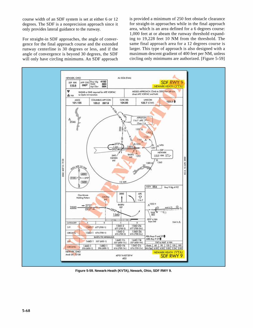
5-68
course width of an SDF system is set at either 6 or 12degrees. The SDF is a nonprecision approach since itonly provides lateral guidance to the runway.
For straight-in SDF approaches, the angle of conver-gence for the final approach course and the extendedrunway centerline is 30 degrees or less, and if theangle of convergence is beyond 30 degrees, the SDFwill only have circling minimums. An SDF approach
is provided a minimum of 250 feet obstacle clearancefor straight-in approaches while in the final approacharea, which is an area defined for a 6 degrees course:1,000 feet at or abeam the runway threshold expand-ing to 19,228 feet 10 NM from the threshold. Thesame final approach area for a 12 degrees course islarger. This type of approach is also designed with amaximum descent gradient of 400 feet per NM, unlesscircling only minimums are authorized. [Figure 5-59]
Figure 5-59. Newark-Heath (KVTA), Newark, Ohio, SDF RWY 9.