Approach of the IEEE to the Application of Low-Voltage SPDs Rev
27
5/14/2008 1 Approach of the IEEE to the Application of Low-Voltage SPDs by Ronald W. Hotchkiss Introduction • IEEE Standards available to: – Define the electrical surge environment – Provide representative waveforms and amplitudes – Supply direction on how to properly and safely test SPDs – Provide guidance on the application of SPDs to electrical systems
Transcript of Approach of the IEEE to the Application of Low-Voltage SPDs Rev

5/14/2008
1
Approach of the IEEEto the Application ofLow-Voltage SPDs
by Ronald W. Hotchkiss
Introduction• IEEE Standards available to:
– Define the electrical surge environment
– Provide representative waveforms and amplitudes
– Supply direction on how to properly and safely test SPDs
– Provide guidance on the application of SPDs to electrical systems

5/14/2008
2
The Surge Environment
• IEEE Std C62.41.1TM-2002– IEEE Guide on the Surge Environment in Low-
Voltage (1000 V and Less) AC Power Circuits
• IEEE Std C62.42TM-2005– IEEE Guide for the Application of Component Surge-
Protective Devices for Use in Low-Voltage [Equal to or Less than 1000 V (ac) or 1200 V (dc)] Circuits
Sources of Electrical Surges
• Lightning– environmental causations
• Switching within the power system (switching surges)– system or component causations

5/14/2008
3
Lightning
• Physical, recognizable• Most often associated with surges• Effects can be prominent and devastating
• Occurs much less frequently than switching surges
Lightning• Direct strike
• Near strike
• Far strike
• Atmospheric charge redistribution

5/14/2008
4
Lightning - Direct• Most severe, high stress• Immediately damaging to
unprotected electronic components and electrical systems
• Mechanical failure• Thermal overstress• Permanent damage• Intervention required
(repairs)
• Involves near-by systems
• Multi-service interaction (communication systems, control circuits, etc.)
Lightning – Nearby• A fraction of current from
a direct strike due to coupling
• Medium to moderate stress
• Typically damaging to unprotected electronic components
• Possibly damaging to electrical systems
• Involves near-by systems
• Multi-service interaction (communication systems, control circuits, etc.)

5/14/2008
5
Lightning - Far• Less induced voltage and
current• Lesser stress than near
or direct• Typically upsetting to
unprotected electronic components
• Repeated events can cause deterioration
• Involves near-by systems
• Multi-service interaction (communication systems, control circuits, etc.)
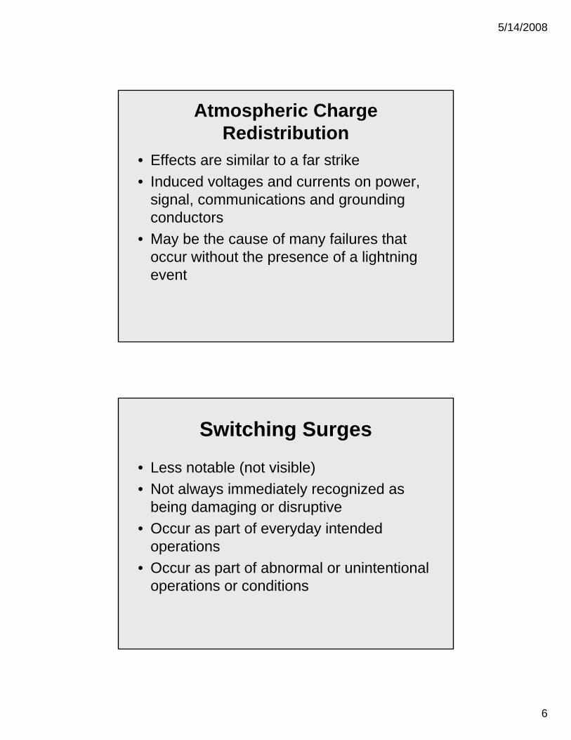
Atmospheric Charge Redistribution
• Not truly lightning• No arc to ground (or vice-versa) or to another
cloud• Rapid movement of charge across a cloud• Often occurs during or just after a lightning strike• Can occur without a lightning strike• Electromagnetic field like a cloud-to-cloud strike
5/14/2008
6
Atmospheric Charge Redistribution
• Effects are similar to a far strike• Induced voltages and currents on power,
signal, communications and grounding conductors
• May be the cause of many failures that occur without the presence of a lightning event
Switching Surges
• Less notable (not visible)• Not always immediately recognized as
being damaging or disruptive• Occur as part of everyday intended
operations• Occur as part of abnormal or unintentional
operations or conditions

5/14/2008
7
Switching Surges• Sources from Normal or Intentional Operations
– Contactors, relays or breakers– Switching of capacitor banks– Stored energy systems– Discharge of inductive devices– Starting and stopping of loads– Fault or arc initiation– Pulsed power loads
Switching Surges
• Sources from Abnormal or Unintentional Operations– Arcing faults or arcing ground faults– Fault clearing– Power system recovery– Loose connections– Lightning induced oscillatory surges

5/14/2008
8
Switching Surges• Frequency 350 Hz to 1000 kHz
• Often represented by 100 kHz
• Amplitudes typically range from a 2-3 times the operating voltage to 6,000 volts or higher
• Occur regularly and frequently – in some cases multiple times per cycle
Switching Surges• Author’s experience: When monitoring a
manufacturing facility using a device intended to record the number of ringing transients occurring over time, over 1,000 surges where recorded within one ten minute interval.
• Source of the surges: The operation of an arc welder in a neighboring facility.

5/14/2008
9
Coupling of Electrical Surges
• Occurs when energy from lightning or switching surges is transferred (coupled) to another system
• Impacts control, communication, data and other systems
• Inductive and capacitive coupling
Coupling of Electrical Surges
• Through multi-service/multi-port loads or even some SPDs
• Often damaging to cabling, connectors or interface of low voltage systems
• From power systems to low voltage systems
• From low voltage systems to power systems

5/14/2008
10
Coupling of Electrical Surges• Due to coupling, failures of components
because of surges can be misinterpreted
• A failed component on the communications side does not necessarily mean the surge originated from that point
• The failed component may have simply provided a low impedance path for the surge when coupled to that system
Surge Testing, Waveforms and Amplitudes
• IEEE Std C62.41.2TM-2002– IEEE Recommended Practice on Characterization of Surges in
Low-Voltage (1000 V and less) AC Power Circuits
• IEEE Std C62.45TM-2002– IEEE Recommended Practice on Surge Testing for Equipment
Connected to Low-Voltage (1000 V and Less) AC Power Circuits
• IEEE Std C62.62-2000– IEEE Standard Test Specifications for Surge-Protective Devices
for Low-Voltage AC Power Circuits

5/14/2008
11
Switching Surges –Ringing/Oscillatory Transients
Represented by a voltage waveform
Lightning Surges –Impulse Transients
Represented by a combination of voltage and current waveforms (combination wave)

5/14/2008
12
Amplitudes
0.2 kA(short circuit current)
6 kV(open circuit voltage)100 kHz Ring WaveLow
0.5 kA(short circuit current)
6 kV(open circuit voltage)Combination WaveLow
Category A Location
0.5 kA(short circuit current)
6 kV(open circuit voltage)100 kHz Ring WaveLow
3 kA(short circuit current)
6 kV(open circuit voltage)Combination WaveHigh
Category B Location
3 kA(short circuit current)
6 kV(open circuit voltage)Combination WaveLow
10 kA(driven through the SPD)
10 kV(minimum)8/20 us CurrentHigh
CurrentVoltageWaveformExposure Level
Category C Location
SPD Application• IEEE C62.72TM-2007
– IEEE Guide for the Application of Surge-Protective Devices for Low-Voltage (1000 V or Less) AC Power Circuits
• IEEE C62.43TM-1999– IEEE Guide for the Application of Surge Protectors Used in Low-Voltage
(Equal to or Less than 1000 Vrms or 1200 Vdc) Data, Communications, and Signaling Circuits
• IEEE 1100TM-2005– IEEE Recommended Practice for Powering and Grounding Electronic
Equipment
• IEEE C62.48TM-2005– IEEE Guide on Interactions Between Power System Disturbances and
Surge-Protective Devices

5/14/2008
13
SPD Application
• Location Categories (C, B, A)…– Category C
• Outside and including the service entrance equipment.
• Service drop from pole or transformer to a building.• Conductors between the utility’s revenue meter
and service entrance equipment.• Overhead line to detached buildings.• Underground line to a well pump or other outdoor
electrical equipment.
SPD Application
• Location Categories (C, B, A)…– Category B
• Service entrance equipment located inside a facility, feeder circuits, and short branch circuits.
• Distribution panelboards and devices.• Busways and feeders in industrial plants.• Heavy appliance outlets with short connections to
the service entrance equipment.• Lighting systems in large buildings or facilities.

5/14/2008
14
SPD Application
• Location Categories (C, B, A)…– Category A
• All outlets at more than about 10 m from Category B.
• All outlets at more than about 20 m from Category C.
IEEE Location Categories

5/14/2008
15
Amplitudes
0.2 kA(short circuit current)
6 kV(open circuit voltage)100 kHz Ring WaveLow
0.5 kA(short circuit current)
6 kV(open circuit voltage)Combination WaveLow
Category A Location
0.5 kA(short circuit current)
6 kV(open circuit voltage)100 kHz Ring WaveLow
3 kA(short circuit current)
6 kV(open circuit voltage)Combination WaveHigh
Category B Location
3 kA(short circuit current)
6 kV(open circuit voltage)Combination WaveLow
10 kA(driven through the SPD)
10 kV(minimum)8/20 us CurrentHigh
CurrentVoltageWaveformExposure Level
Category C Location
Available Short-Circuit Currentand SPDs
• SPDs are tested to failure at various levels of available short-circuit current
• The highest current used is the SPD’s short-circuit current rating (SCCR)
• SCCR’s typically range from about 5,000 to 200,000 Amps – determined during the listing of the SPD
• The SCCR of an SPD must be higher than the available short-circuit current at the location of installation within the electrical system

5/14/2008
16
Available Short-Circuit Currentand SPDs
• If the available short-circuit current of the system at the point of installation is higher than the SCCR of the SPD, a different SPD must be selected or provisions made to limit the available short-circuit current at the point of application
• This is an NEC requirement
Coordination of an SPD with a Fuse or Breaker
• Many SPDs require an external fuse or breaker as part of their listing
• This requirement is required to appear on the SPD or in the installation instructions with the SPD
• Installation without the specified fuse or breaker violates the listing of the SPD
5/14/2008
17
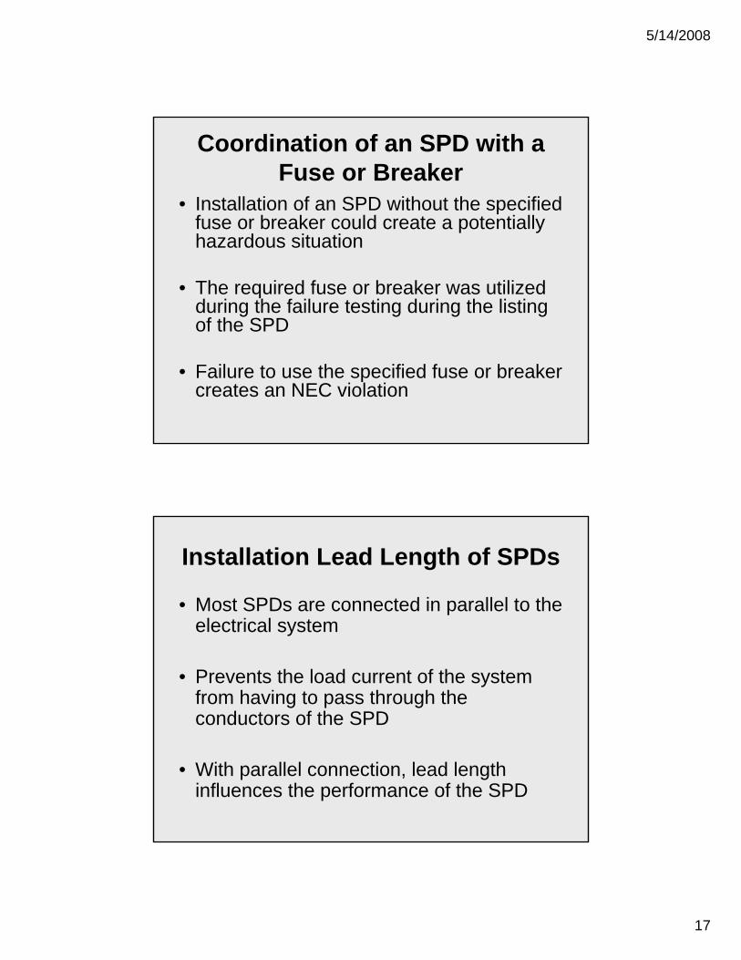
Coordination of an SPD with a Fuse or Breaker
• Installation of an SPD without the specified fuse or breaker could create a potentially hazardous situation
• The required fuse or breaker was utilized during the failure testing during the listing of the SPD
• Failure to use the specified fuse or breaker creates an NEC violation
Installation Lead Length of SPDs
• Most SPDs are connected in parallel to the electrical system
• Prevents the load current of the system from having to pass through the conductors of the SPD
• With parallel connection, lead length influences the performance of the SPD

5/14/2008
18
• Parallel connection
– Voltage drop is about 1 kV/m of lead length for 1 kA/us waveform
– The longer the connecting leads – the higher the let-through voltage
– Most SPDs are tested with 15 cm (6”) of lead length
Installation Lead Length of SPDs
Installation Lead Length of SPDs
• Parallel connection
– Make leads as short as possible
– Shape to minimize open-loop geometry
– Twist leads together – avoid sharp bends

5/14/2008
19
Specifying SPDs
• IEEE C62.72TM-2007– IEEE Guide for the Application of Surge-
Protective Devices for Low-Voltage (1000 V or Less) AC Power Circuits
• Clause 9– Specification and Application questions
Surge Mitigation and SPDs• Surge Protective Devices (SPDs)
– For both power and low voltage systems (communication, data, control, transducers, coaxial connections, etc.)
– Paramount to providing reliability and quality power
– Decrease opportunity for systems failure due to surges

5/14/2008
20
Surge Mitigation and SPDs• Essential to promote survivability
• Reduce equipment loss, repairs, restarts and downtime
• Aids in providing uninterrupted service
SPDs Action - ImpulseBefore After
6,200 Vpk 562 Vpk

5/14/2008
21
SPDs Action – Ringing Surge(SPD with no filter circuitry)
Before After
6,000 Vpk 442 Vpk
SPDs Action – Ringing Surge(SPD with filter circuitry)
Before After
6,000 Vpk 123 Vpk

5/14/2008
22
SPD Action
Open Circuit 6 kV, 500 A Ring Wave
Clamping device only
w/ Filter
All on the same scale.
Application Photos(Typical Panel Installation – TV Broadcast Location)

5/14/2008
23
Application Photos(Generator Protection)
Application Photos(Transfer Switch Protection)

5/14/2008
24
Application Photos(Digital Sign Controller Circuit)
Application Photos(Service Disconnect and Sub-Panels)

5/14/2008
25
Application Photos (Drive Protection)
Summary
• Surge environment – surges from a wide variety of sources
• Surges will propagate along and couple across systems
• Surges are harmful to key components and systems relied upon for operation

5/14/2008
26
Summary
• SPDs help to mitigate the effects of surges
• SPDs promote:– Power quality– Uptime– System performance– Reliability
References
• IEEE Recommended Practice for Powering and Grounding Electronic Equipment, IEEE Standard 1100-2005
• IEEE Guide on Interactions Between Power System Disturbances and Surge-Protective Devices, IEEE Standard C62.48™-2005
• IEEE Guide for the Application of Component Surge-Protective Devices for Use in Low-Voltage [Equal to or Less than 1000 V (ac) or 1200 V (dc)] Circuits, IEEE Std C62.42™-2005
• IEEE Guide on the Surge Environment in Low-Voltage (1000 V and Less) AC Power Circuits, IEEE Standard C62.41.1™-2002
• IEEE Recommended Practice on Characterization of Surges in Low-Voltage (1000 V and less) AC Power Circuits, IEEE Standard C62.41.2™-2002
• F. Martzloff, G. Pellegrini, “Real, realistic ring waves for surge testing”, Ninth International Zurich Symposium on Electromagnetic Compatibility, 1991
• F. Martzloff, “Coupling, propagation, and side effects of surges in an industrial building wiring system”, IEEE Trans. On Industry Applications IA-26, 1989
• F. Martzloff, “The propagation and attenuation of surge voltages and surge currents in low-voltage ac circuits”, IEEE Summer Meeting, July 1982
• B. R. Cole, K. Brown, P. S. McCurdy, T. Phipps, R. Hotchkiss, “The short circuit current ratings of surge protective devices (SPDs)”, IEEE Power Engineering Society General Meeting, June 2006
• IEEE Recommended Practice on Surge Testing for Equipment Connected to Low-Voltage (1000 V and Less) AC Power Circuits, IEEE Std C62.45™-2002
• IEEE Standard Test Specifications for Surge-Protective Devices for Low-Voltage AC Power Circuits, IEEE Std C62.62-2000
• IEEE Guide for the Application of Surge-Protective Devices for Low-Voltage (1000 V or Less) AC Power Circuits, IEEE Std C62.72™-2007
• F. Martzloff, K. Phipps, “Lingering lead length legacies in surge-protective devices applications”, IEEE Trans. On Power Delivery, V19-I1, 2004

5/14/2008
27
Thank You!