APPLYING PROVEN DREDGE DESIGNS IN A NON … · APPLYING PROVEN DREDGE DESIGNS IN A NON-STANDARD...
14
DREDGING SUMMIT & EXPO ’17 PROCEEDINGS APPLYING PROVEN DREDGE DESIGNS IN A NON-STANDARD SITUATION; THE OIL SANDS O.P. Marcus 1 , M. Tijssen 2 and M.O. Winkelman 3 ABSTRACT Dredging in the oil sands industry provides a number of specific challenges. The approach to these challenges will determine a project’s success. There is a wide range of challenges, like the variety in slurries, environmental conditions, remote operating areas, the presence of muskeg and bitumen in slurry etc. Since two years another important challenge has entered the arena; the economic climate has changed dramatically which doesn’t allow fully one-off engineered solutions to the specific needs. A flexible, multi – employable and low cost approach is required. The DAMEN approach consists of using a modular Cutter Suction Dredge ( CSD) as a platform. This platform can be customized with a series of equipment to face the specific projects requirements. As the range of CSD’s is a fully engineered product line (build on stock), where the required preparations for optional equipment are included in the design, customizations for application in the oil sands are easy to install. This results in a low cost “adjust-to-order” CSD’s with a short delivery time. Furthermore, once the original project is finished, this CSD can easily be converted to face new challenges in next projects, increasing the economic life time of the dredge. The developed tools are add-ons to the standard product. An extensive research and engineering project is initiated using experience from the field. Several scale model and real size tests are performed in vitro at our yard, where all in-house design pumps can be put to the challenge. The flexible customization results in a cost effective and reliable range of add-on tools to face typical oil sand challenges. Keywords: Dredging, beneficial uses, slurry transport, dredged material disposal, contaminated sediment. INTRODUCTION Worldwide conventional oil resources are increasingly depleted. For this reason, alternative methods for extracting oil are becoming more attractive economically. One of these methods is the extraction of oil from bitumen sands. The largest stocks of bituminous sands are found in Venezuela, the Orinoco oil supply, and in Canada, the Athabasca region in the province of Alberta. In Venezuela, the stocks are estimated at 1200 billion barrels, of which 235 billion barrels are economically recoverable. Canadian stocks are estimated at 1700 billion barrels, of which 169.3 billion barrels are economically recoverable. The oil reserves of bituminous sands is Venezuela at number 1 and number 3 in Canada in the ranking of global oil reserves. (Saniere et al. 2004) In Canada a new mine has been opened: the Kearl Oil Sands Project is an oil sands mine in the Athabasca Oil Sands region at the Kearl Lake area, about 70 kilometres (43 mi) north of Fort McMurray in Alberta, Canada (Figure 1). The project is being developed in three phases with the first phase completed mid-2013. At the first stage the development would involve capital spending of about C$8 billion, with the final estimate being highly dependent on the final upgrading option selected. An engineering, procurement, and construction management contract for the first phase was awarded to AMEC while Fluor Corp. is responsible for the development of infrastructure and facilities. 1 Product Director Dredging, Damen Shipyards, Avelingen West 20, Gorinchem, ZH, 4202 MS, the Netherlands, +31 183 655409, [email protected]. 2 Sales Manager, Dredging, Damen Shipyards, Avelingen West 20, Gorinchem, ZH, 4202 MS, the Netherlands, +31 183 653358, [email protected]. 3 Manager Research, Damen Dredging Equipment, Edisonstraat 32, Nijkerk, Gld, 3861 NE, the Netherlands, +31 33 2474040, [email protected]. 417
Transcript of APPLYING PROVEN DREDGE DESIGNS IN A NON … · APPLYING PROVEN DREDGE DESIGNS IN A NON-STANDARD...

DREDGING SUMMIT & EXPO ’17 PROCEEDINGS
APPLYING PROVEN DREDGE DESIGNS IN A NON-STANDARD SITUATION;
THE OIL SANDS
O.P. Marcus1, M. Tijssen2 and M.O. Winkelman3
ABSTRACT
Dredging in the oil sands industry provides a number of specific challenges. The approach to these challenges will determine a project’s success.
There is a wide range of challenges, like the variety in slurries, environmental conditions, remote operating areas, the presence of muskeg and bitumen in slurry etc. Since two years another important challenge has entered the arena; the economic climate has changed dramatically which doesn’t allow fully one-off engineered solutions to the specific needs. A flexible, multi – employable and low cost approach is required.
The DAMEN approach consists of using a modular Cutter Suction Dredge ( CSD) as a platform. This platform can be customized with a series of equipment to face the specific projects requirements. As the range of CSD’s is a fully engineered product line (build on stock), where the required preparations for optional equipment are included in the design, customizations for application in the oil sands are easy to install. This results in a low cost “adjust-to-order” CSD’s with a short delivery time. Furthermore, once the original project is finished, this CSD can easily be converted to face new challenges in next projects, increasing the economic life time of the dredge. The developed tools are add-ons to the standard product.
An extensive research and engineering project is initiated using experience from the field. Several scale model and real size tests are performed in vitro at our yard, where all in-house design pumps can be put to the challenge.
The flexible customization results in a cost effective and reliable range of add-on tools to face typical oil sand challenges.
Keywords: Dredging, beneficial uses, slurry transport, dredged material disposal, contaminated sediment.
INTRODUCTION
Worldwide conventional oil resources are increasingly depleted. For this reason, alternative methods for extracting oil are becoming more attractive economically. One of these methods is the extraction of oil from bitumen sands. The largest stocks of bituminous sands are found in Venezuela, the Orinoco oil supply, and in Canada, the Athabasca region in the province of Alberta. In Venezuela, the stocks are estimated at 1200 billion barrels, of which 235 billion barrels are economically recoverable. Canadian stocks are estimated at 1700 billion barrels, of which 169.3 billion barrels are economically recoverable. The oil reserves of bituminous sands is Venezuela at number 1 and number 3 in Canada in the ranking of global oil reserves. (Saniere et al. 2004)
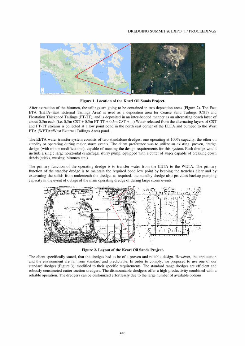
In Canada a new mine has been opened: the Kearl Oil Sands Project is an oil sands mine in the Athabasca Oil Sands region at the Kearl Lake area, about 70 kilometres (43 mi) north of Fort McMurray in Alberta, Canada (Figure 1). The project is being developed in three phases with the first phase completed mid-2013. At the first stage the development would involve capital spending of about C$8 billion, with the final estimate being highly dependent on the final upgrading option selected. An engineering, procurement, and construction management contract for the first phase was awarded to AMEC while Fluor Corp. is responsible for the development of infrastructure and facilities.
1 Product Director Dredging, Damen Shipyards, Avelingen West 20, Gorinchem, ZH, 4202 MS, the Netherlands, +31 183 655409, [email protected].
2 Sales Manager, Dredging, Damen Shipyards, Avelingen West 20, Gorinchem, ZH, 4202 MS, the Netherlands, +31 183 653358, [email protected].
3 Manager Research, Damen Dredging Equipment, Edisonstraat 32, Nijkerk, Gld, 3861 NE, the Netherlands, +31 33 2474040, [email protected].
417
DREDGING SUMMIT & EXPO ’17 PROCEEDINGS
Figure 1. Location of the Kearl Oil Sands Project.
After extraction of the bitumen, the tailings are going to be contained in two deposition areas (Figure 2). The East ETA (EETA=East External Tailings Area) is used as a deposition area for Coarse Sand Tailings (CST) and Floatation Thickened Tailings (FT-TT), and is deposited in an inter-bedded manner as an alternating beach layer of about 0.5m each (i.e. 0.5m CST + 0.5m FT-TT + 0.5m CST + ...) Water released from the alternating layers of CST and FT-TT streams is collected at a low point pond in the north east corner of the EETA and pumped to the West ETA (WETA=West External Tailings Area) pond.
The EETA water transfer system consists of two standalone dredges: one operating at 100% capacity, the other on standby or operating during major storm events. The client preference was to utilize an existing, proven, dredge design (with minor modifications), capable of meeting the design requirements for this system. Each dredge would include a single large horizontal centrifugal slurry pump, equipped with a cutter of auger capable of breaking down debris (sticks, muskeg, bitumen etc.)
The primary function of the operating dredge is to transfer water from the EETA to the WETA. The primary function of the standby dredge is to maintain the required pond low point by keeping the trenches clear and by excavating the solids from underneath the dredge, as required. the standby dredge also provides backup pumping capacity in the event of outage of the main operating dredge of during large storm events.
Figure 2. Layout of the Kearl Oil Sands Project.
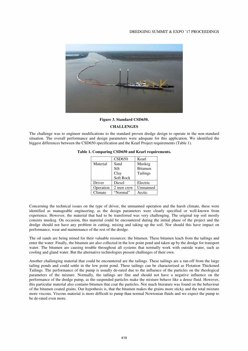
The client specifically stated, that the dredges had to be of a proven and reliable design. However, the application and the environment are far from standard and predictable. In order to comply, we proposed to use one of our standard dredges (Figure 3), modified to their specific requirements. The standard range dredges are efficient and robustly constructed cutter suction dredgers. The dismountable dredgers offer a high productivity combined with a reliable operation. The dredgers can be customized effortlessly due to the large number of available options.
418
DREDGING SUMMIT & EXPO ’17 PROCEEDINGS
Figure 3. Standard CSD650.
CHALLENGES
The challenge was to engineer modifications to the standard proven dredge design to operate in the non-standard situation. The overall performance and design parameters were adequate for this application. We identified the biggest differences between the CSD650 specification and the Kearl Project requirements (Table 1).
Table 1. Comparing CSD650 and Kearl requirements.
CSD650 Kearl
Material Sand Silt Clay Soft Rock
Muskeg Bitumen Tailings
Driver Diesel Electric
Operation 2 men crew Unmanned
Climate “Normal” Arctic
Concerning the technical issues on the type of driver, the unmanned operation and the harsh climate, these were identified as manageable engineering, as the design parameters were clearly specified or well-known from experience. However, the material that had to be transferred was very challenging. The original top soil mostly consists muskeg. On occasion, this material could be encountered during the initial phase of the project and the dredge should not have any problem in cutting, mixing and taking up the soil. Nor should this have impact on performance, wear and maintenance of the rest of the dredge.
The oil sands are being mined for their valuable resources: the bitumen. These bitumen leach from the tailings and enter the water. Finally, the bitumen are also collected in the low point pond and taken up by the dredge for transport water. The bitumen are causing trouble throughout all systems that normally work with outside water, such as cooling and gland water. But the alternative technologies present challenges of their own.
Another challenging material that could be encountered are the tailings. These tailings are a run-off from the large tailing ponds and could settle in the low point pond. These tailings can be characterised as Flotation Thickened Tailings. The performance of the pump is usually de-rated due to the influence of the particles on the rheological parameters of the mixture. Normally, the tailings are fine and should not have a negative influence on the performance of the dredge pump, as the suspended particles make the mixture behave like a dense fluid. However, this particular material also contains bitumen that coat the particles. Not much literature was found on the behaviour of the bitumen coated grains. Our hypothesis is, that the bitumen makes the grains more sticky and the total mixture more viscous. Viscous material is more difficult to pump than normal Newtonian fluids and we expect the pump to be de-rated even more.
419
DREDGING SUMMIT & EXPO ’17 PROCEEDINGS
These three main challenges, muskeg, bitumen and tailings, were approached each with their own research and development project.
DEVELOPMENT
Muskeg
Muskeg characterisation
The requirements specifically mentioned that there was muskeg to be encountered. This soil material is very common in Canada, but little known in the rest of the world. So we investigated the peculiarities of this material.
Muskeg is an acidic soil type common in Arctic and boreal areas, although it is found in other northern climates as well. Muskeg is approximately synonymous with bog land, but "muskeg" is the standard term in Western Canada and Alaska, while 'bog' is common elsewhere. Muskeg consists of dead plants in various states of decomposition (as peat), ranging from fairly intact sphagnum moss, to sedge peat, to highly decomposed humus. Pieces of wood can make up five to 15 percent of the peat soil. Muskeg tends to have a water table near the surface. The sphagnum moss forming it can hold 15 to 30 times its own weight in water, allowing the spongy wet muskeg to form on sloping ground. Small stands of stunted and often dead trees, which vaguely resemble Bonsai trees, grow where land protrudes above the water table, with small pools of water stained dark red scattered about.
Although the natural environment of the oil sands in Canada are quite special, the resulting impact on the material to be dredged, is quite familiar to the Dutch county side. Holland used to be only bogs and swamps but due to cultivation only a small fraction of this original nature remains. One such area in the Netherlands is the “National Park of the Weerribben-Wieden”. In this park, the soil contains lots of weed and wood and resembles the debris found in muskeg.
The landscape of the Weerribben and De Wieden is mainly caused by peat and reed cultivation with some original bushes of birch and willow. These exploration and exploitation methods have led to a mosaic of landscapes and ecosystems such as lakes, ditches, canals, reed beds, meadows, pastures, swamps and quaking bogs. The different stages of hydrosere, from open water to swamp upright, giving the area a huge ecological diversity where rare species of plants and animals feel at home For the restoration of the connection between the two parts, a very special amphibious cutter suction dredge: “Suzanna II” (Figure 4. Susanna II at work in the “Weerribben”.)
Introduction to the Susanna II
Figure 4. Susanna II at work in the “Weerribben”.
The "Susanna II" is a fully dismountable cutter suction dredger equipped with a 250 mm discharge pipeline. It was fitted out with a swing ladder for dredging at a maximum depth of 6 metres. The dividable swing ladder has a total length of 18 metres, which delivers an impressive and hyper-efficient swing width of 28 metres. Moreover, the "Susanna II" is equipped with a spud carriage installation with a 2 meter stroke and spuds that can work both on land and water. The control cabin can be dismantled so as to keep the maximum height of the full dredger under 1.5
420

DREDGING SUMMIT & EXPO ’17 PROCEEDINGS
metres for swift passages under low bridges. For easy transport, the modularly designed dredger comes apart into a main pontoon, four side pontoons, the control cabin, the spuds and the dividable cutter ladder, all of which can then be transported by road.
Development of a swamp cutter
The success of the “Susanna II” is that it was able to continuously work in the debris riddled peat and bog soil of the “Weerrribben”. The soil itself can be normally cut with the usual crown cutter. The problems arise when the branches and tree stubs enter the cutter head. They get stuck in the suction mouth and force the crown cutter to a full stop. As the debris is forced by the cutter drive into the suction mouth the wood is wedged in place and very hard to remove. A solution that was applied at the “Suzanna II” was to install branch breakers inside of the crown cutter (Figure 1). They are attached to the back ring and an additional ring around the shaft of the cutter. They pass the suction mouth very closely and any long debris that is forced into the suction mouth, gets snipped in smaller pieces. The spacing of the branch breakers is such, that the chips that pass the suction mouth are smaller than the spherical passage of the following dredge pump and pass there easily also.
Figure 5. Cutter head with branch breakers installed.
Bitumen
Problems of bitumen in service water
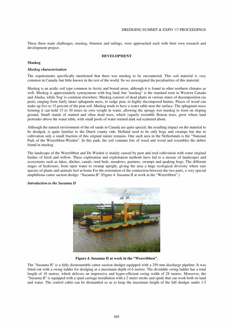
Bitumen is a sticky substance, contaminates systems relying on outside water. So, the usual cooling and gland water systems had to be reconsidered. Instead of water cooling, air cooled radiators were applied. However, the biggest advantage of the standard dredge design is, that it is normally equipped with a mechanical seal (Figure 6) on the shaft of the dredge pump. This type of seal, does not require any gland water at all. A concern for the mechanical seal, is that it relies on the gap between the two ceramic rings. The contact surface is actually extremely smooth and an ultra-thin layer of fluid lubricates the surfaces. This lubrication forces the rings to part for a very small gap. This gap is small enough, that the adhesion of the lubricating fluid can withstand a pressure differential and creates the seal. Still, there is this gap, and if particles are smaller than this gap, they can enter the lubricating fluid between the ceramic rings. Once there, they can disrupt the lubrication and cause damage to that smooth surface. Damage may accumulate and in the end, the mechanical seal will fail.
421
DREDGING SUMMIT & EXPO ’17 PROCEEDINGS
Figure 6. Cut away exhibit of a mechanical seal for dredge pumps.
Investigation of particle passage through the mechanical seal
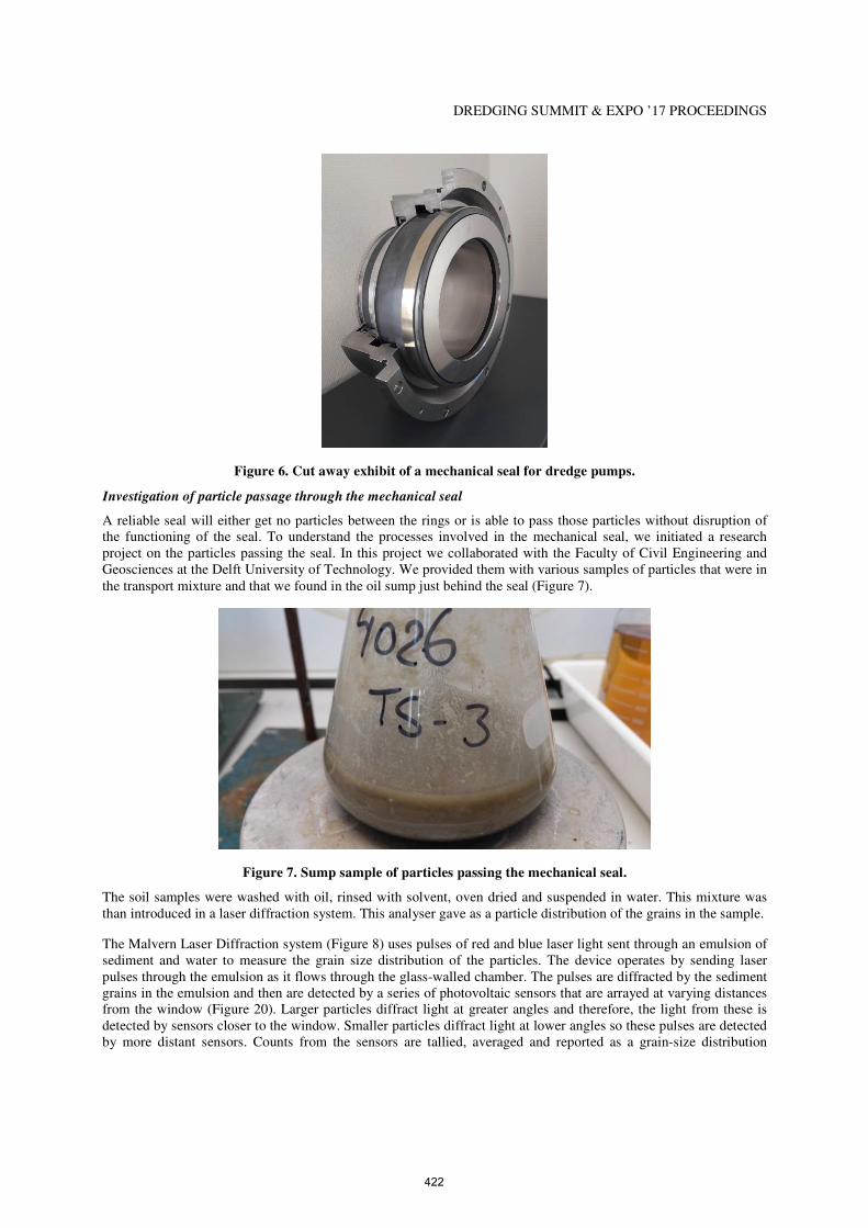
A reliable seal will either get no particles between the rings or is able to pass those particles without disruption of the functioning of the seal. To understand the processes involved in the mechanical seal, we initiated a research project on the particles passing the seal. In this project we collaborated with the Faculty of Civil Engineering and Geosciences at the Delft University of Technology. We provided them with various samples of particles that were in the transport mixture and that we found in the oil sump just behind the seal (Figure 7).
Figure 7. Sump sample of particles passing the mechanical seal.
The soil samples were washed with oil, rinsed with solvent, oven dried and suspended in water. This mixture was than introduced in a laser diffraction system. This analyser gave as a particle distribution of the grains in the sample.
The Malvern Laser Diffraction system (Figure 8) uses pulses of red and blue laser light sent through an emulsion of sediment and water to measure the grain size distribution of the particles. The device operates by sending laser pulses through the emulsion as it flows through the glass-walled chamber. The pulses are diffracted by the sediment grains in the emulsion and then are detected by a series of photovoltaic sensors that are arrayed at varying distances from the window (Figure 20). Larger particles diffract light at greater angles and therefore, the light from these is detected by sensors closer to the window. Smaller particles diffract light at lower angles so these pulses are detected by more distant sensors. Counts from the sensors are tallied, averaged and reported as a grain-size distribution
422

DREDGING SUMMIT & EXPO ’17 PROCEEDINGS
(Figure 21 and Figure 22). Grains from 0.001 mm to 2 mm in diameter can be detected. Analyses are repeatable to ±0.5%.
Figure 8. Concept of the laser diffraction system.
Eventually, the result of the back scatter analysis is the particle size distribution (Figure 9).
Figure 9. Particle Size Distribution of sump sample.
In the graph you can see, that the biggest particles fitting through the gap are 8µm. We may safely assume, that this is also about the size of the gap in working condition. Another observation is, that most of the particles passing through are 0.2µm and 2µm. Generally, they are still smaller, than the indications for the particle size in the tailings. The particles specified in the Kearl Project are in the range of 44µm. The actual particle size distribution was not available. So, there might be a part of the tailing that might pass the gap. However, as the above analysed distribution passed the seal gap without any serious consequences for the seal, the installed mechanical seal should operate reliably in this non-standard situation.
Tailings
Explanation on tailings
Sand Bitumen is composed of 80-85% minerals, 10-15% of bitumen and 3-4% water. The minerals consist of sand and clay. The sand is mainly composed of quartz, the clay particles consist of kaolinite, illite and montmorillonite. By means of a hot water process called "Clark Hot Water Process", the bitumen will be withdrawn from the bitumen
423

DREDGING SUMMIT & EXPO ’17 PROCEEDINGS
sand. Once the bitumen sands are excavated and pulverised, hot water (50-80°C) is added. The hot water makes the bitumen less viscous and thereby separates better from the sand grains. The separation process is accelerated through a variety of mixing methods and by means of air bubbles. The bitumen attach to the bubbles and float to the top where they are then collected. The bitumen are processed for further transport to a refinery through pipelines. For the removal of the bitumen from the minerals a lot of water is being used, and a residual product is left over, most is sand, and the other will be a residual product referred to as "tailings". There is between two and four tons of bitumen and sand needed and two to four barrels of water required to produce one barrel of bitumen. The tailings are stored in large lakes called "Tailings Ponds" (Figure 10). In these lakes, segregation will take place where the heaviest particles (sand) will sink to the bottom. The water will rise to the top layer of the lake and is reused in the extraction process. The lake will form several layers. The first layer which forms are among the water layer "Thin Fine Tailings" (TFT) or "non-settling tailings". TFT be a layer of clay particles (30%) and water (70%). The TFT will consolidate and after a period of seen about three years as a "Mature Fine Tailings" (MFT) because the rate fixed substances than is greater than thirty percent. (Mamer 2010).
Figure 10. Layers within a tailings pond.
The geological history of the oil sands, causes the sand particles to be covered in a very thin film of water, and then the wet particle is enveloped in a thicker sheet of bitumen (Figure 11).
Figure 11. Composition of tailings particles.
Based on various sources of literature (Boratynec, 2003), (Farkish, 2013), (Owolagba et al. 2013), the upper and lower boundaries of the tailings were established (Table 2). This provided a guideline for the search of a similar material that could be used in the experiments.
424
DREDGING SUMMIT & EXPO ’17 PROCEEDINGS
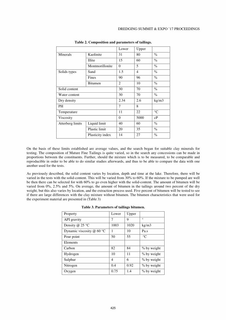
Table 2. Composition and parameters of tailings.
Lower Upper
Minerals Kaolinite 31 80 %
Illite 15 60 %
Montmorillonite 0 5 %
Solids types Sand 1.5 4 %
Fines 90 96 %
Bitumen 2 10 %
Solid content 30 70 %
Water content 30 70 %
Dry density 2.34 2.6 kg/m3
PH 7 8
Temperature 11 22 °C
Viscosity 0 5000 cP
Atterberg limits Liquid limit 40 60 %
Plastic limit 20 35 %
Plasticity index 14 27 %
On the basis of these limits established are average values, and the search began for suitable clay minerals for testing. The composition of Mature Fine Tailings is quite varied, so in the search any concessions can be made in proportions between the constituents. Further, should the mixture which is to be measured, to be comparable and reproducible in order to be able to do similar studies afterwards, and thus to be able to compare the data with one another used for the tests.
As previously described, the solid content varies by location, depth and time at the lake. Therefore, there will be varied in the tests with the solid-content. This will be varied from 30% to 60%. If the mixture to be pumped are well be then there can be selected for with 60% to go even higher with the solid-content. The amount of bitumen will be varied from 0%, 2.5% and 5%. On average, the amount of bitumen in the tailings around two percent of the dry weight, but this also varies by location, and the extraction process used. Five percent of bitumen will be tested to see if there are large differences with the clay mixture without bitumen. The bitumen characteristics that were used for the experiment material are presented in (Table 3)
Table 3. Parameters of tailings bitumen.
Property Lower Upper
API gravity 7 9 °
Density @ 25 °C 1003 1020 kg/m3
Dynamic viscosity @ 60 °C 1 10 Pa.s
Pour point 50 55 °C
Elements
Carbon 82 84 % by weight
Hydrogen 10 11 % by weight
Sulphur 4 6 % by weight
Nitrogen 0.4 0.92 % by weight
Oxygen 0.75 1.4 % by weight
425
DREDGING SUMMIT & EXPO ’17 PROCEEDINGS
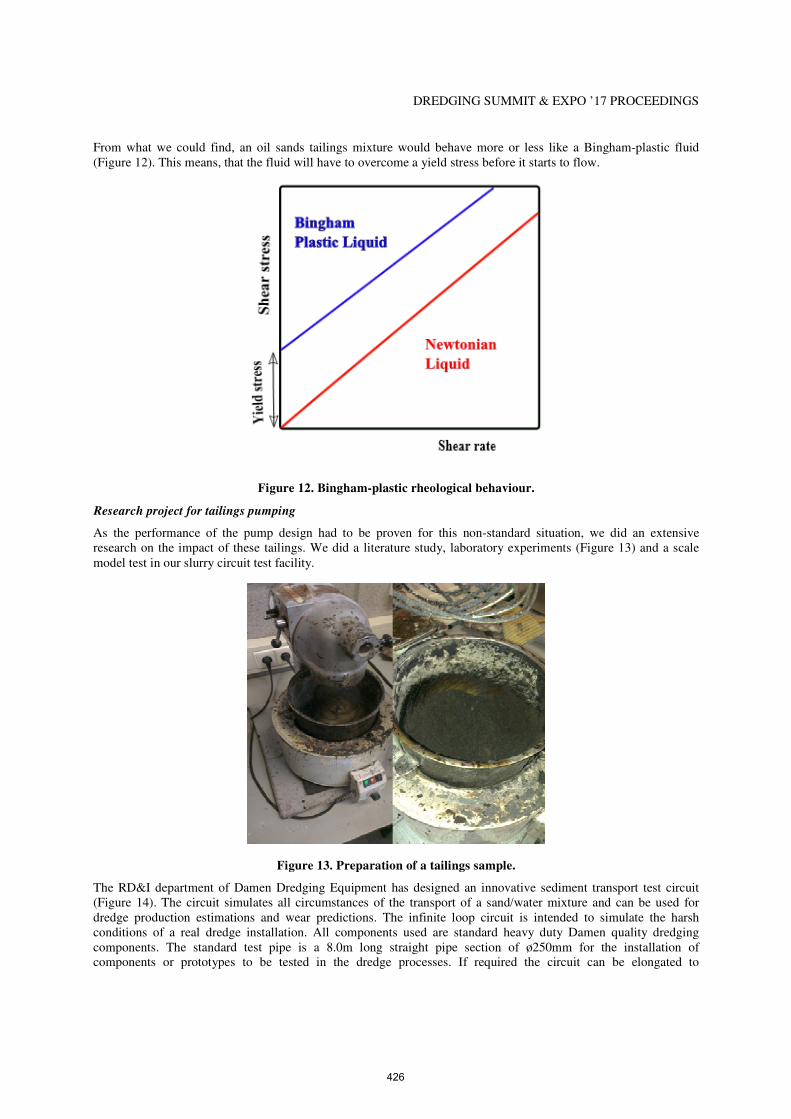
From what we could find, an oil sands tailings mixture would behave more or less like a Bingham-plastic fluid (Figure 12). This means, that the fluid will have to overcome a yield stress before it starts to flow.
Figure 12. Bingham-plastic rheological behaviour.
Research project for tailings pumping
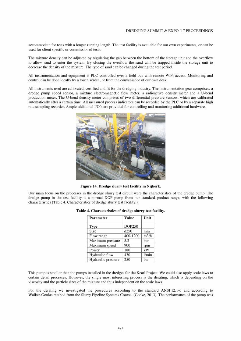
As the performance of the pump design had to be proven for this non-standard situation, we did an extensive research on the impact of these tailings. We did a literature study, laboratory experiments (Figure 13) and a scale model test in our slurry circuit test facility.
Figure 13. Preparation of a tailings sample.
The RD&I department of Damen Dredging Equipment has designed an innovative sediment transport test circuit (Figure 14). The circuit simulates all circumstances of the transport of a sand/water mixture and can be used for dredge production estimations and wear predictions. The infinite loop circuit is intended to simulate the harsh conditions of a real dredge installation. All components used are standard heavy duty Damen quality dredging components. The standard test pipe is a 8.0m long straight pipe section of ø250mm for the installation of components or prototypes to be tested in the dredge processes. If required the circuit can be elongated to
426
DREDGING SUMMIT & EXPO ’17 PROCEEDINGS
accommodate for tests with a longer running length. The test facility is available for our own experiments, or can be used for client specific or commissioned tests.
The mixture density can be adjusted by regulating the gap between the bottom of the storage unit and the overflow to allow sand to enter the system. By closing the overflow the sand will be trapped inside the storage unit to decrease the density of the mixture. The type of sand can be changed during the test period.
All instrumentation and equipment is PLC controlled over a field bus with remote WiFi access. Monitoring and control can be done locally by a touch screen, or from the convenience of our own desk.
All instruments used are calibrated, certified and fit for the dredging industry. The instrumentation gear comprises: a dredge pump speed sensor, a mixture electromagnetic flow meter, a radioactive density meter and a U-bend production meter. The U-bend density meter comprises of two differential pressure sensors, which are calibrated automatically after a certain time. All measured process indicators can be recorded by the PLC or by a separate high rate sampling recorder. Ample additional I/O’s are provided for controlling and monitoring additional hardware.
Figure 14. Dredge slurry test facility in Nijkerk.
Our main focus on the processes in the dredge slurry test circuit were the characteristics of the dredge pump. The dredge pump in the test facility is a normal DOP pump from our standard product range, with the following characteristics (Table 4. Characteristics of dredge slurry test facility.):
Table 4. Characteristics of dredge slurry test facility.
Parameter Value Unit
Type DOP250
Size ø250 mm
Flow range 400-1200 m3/h
Maximum pressure 5.2 bar
Maximum speed 900 rpm
Power 180 kW
Hydraulic flow 430 l/min
Hydraulic pressure 250 bar
This pump is smaller than the pumps installed in the dredges for the Kearl Project. We could also apply scale laws to certain detail processes. However, the single most interesting process is the derating, which is depending on the viscosity and the particle sizes of the mixture and thus independent on the scale laws.
For the derating we investigated the procedures according to the standard ANSI 12.1-6 and according to Walker-Goulas method from the Slurry Pipeline Systems Course. (Cooke, 2013). The performance of the pump was
427
DREDGING SUMMIT & EXPO ’17 PROCEEDINGS
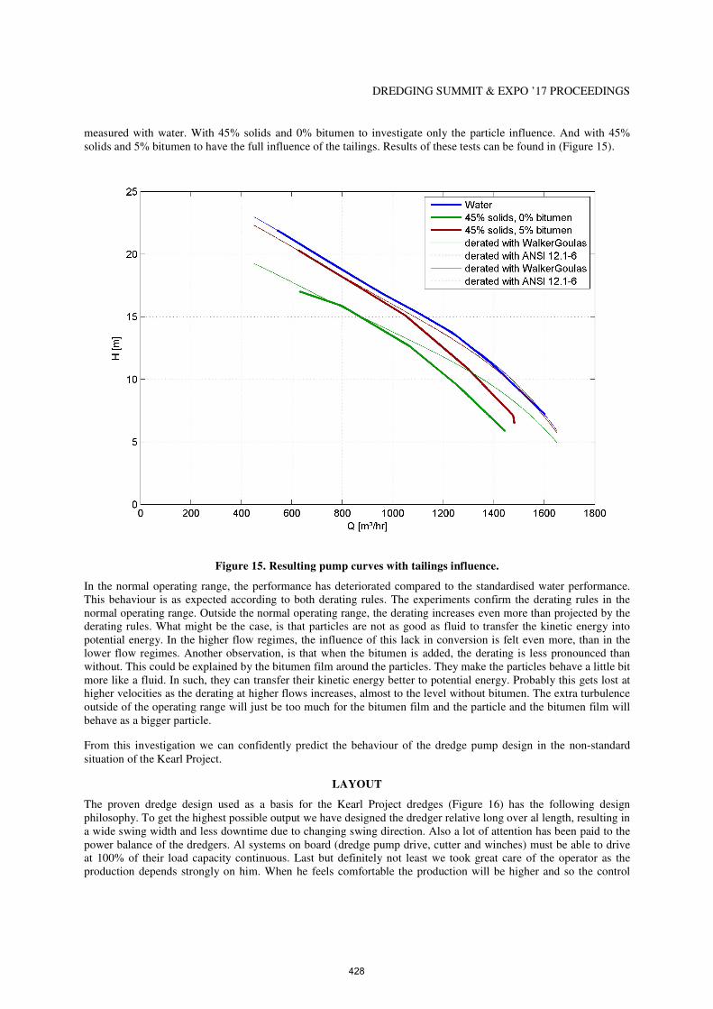
measured with water. With 45% solids and 0% bitumen to investigate only the particle influence. And with 45% solids and 5% bitumen to have the full influence of the tailings. Results of these tests can be found in (Figure 15).
Figure 15. Resulting pump curves with tailings influence.
In the normal operating range, the performance has deteriorated compared to the standardised water performance. This behaviour is as expected according to both derating rules. The experiments confirm the derating rules in the normal operating range. Outside the normal operating range, the derating increases even more than projected by the derating rules. What might be the case, is that particles are not as good as fluid to transfer the kinetic energy into potential energy. In the higher flow regimes, the influence of this lack in conversion is felt even more, than in the lower flow regimes. Another observation, is that when the bitumen is added, the derating is less pronounced than without. This could be explained by the bitumen film around the particles. They make the particles behave a little bit more like a fluid. In such, they can transfer their kinetic energy better to potential energy. Probably this gets lost at higher velocities as the derating at higher flows increases, almost to the level without bitumen. The extra turbulence outside of the operating range will just be too much for the bitumen film and the particle and the bitumen film will behave as a bigger particle.
From this investigation we can confidently predict the behaviour of the dredge pump design in the non-standard situation of the Kearl Project.
LAYOUT
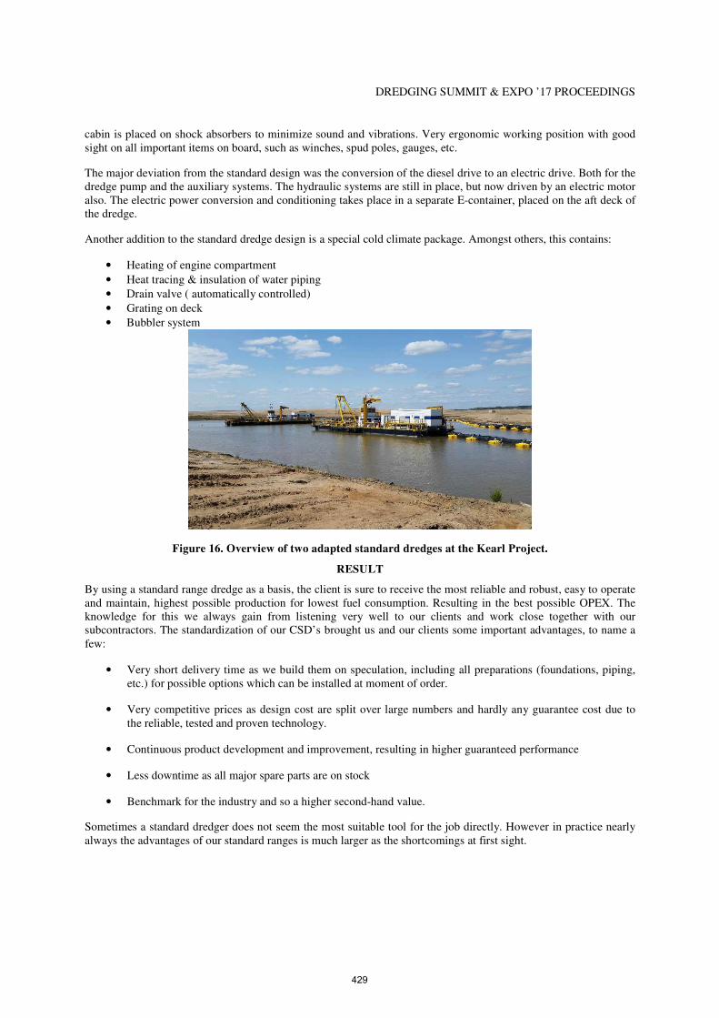
The proven dredge design used as a basis for the Kearl Project dredges (Figure 16) has the following design philosophy. To get the highest possible output we have designed the dredger relative long over al length, resulting in a wide swing width and less downtime due to changing swing direction. Also a lot of attention has been paid to the power balance of the dredgers. Al systems on board (dredge pump drive, cutter and winches) must be able to drive at 100% of their load capacity continuous. Last but definitely not least we took great care of the operator as the production depends strongly on him. When he feels comfortable the production will be higher and so the control
428
DREDGING SUMMIT & EXPO ’17 PROCEEDINGS
cabin is placed on shock absorbers to minimize sound and vibrations. Very ergonomic working position with good sight on all important items on board, such as winches, spud poles, gauges, etc.
The major deviation from the standard design was the conversion of the diesel drive to an electric drive. Both for the dredge pump and the auxiliary systems. The hydraulic systems are still in place, but now driven by an electric motor also. The electric power conversion and conditioning takes place in a separate E-container, placed on the aft deck of the dredge.
Another addition to the standard dredge design is a special cold climate package. Amongst others, this contains:
• Heating of engine compartment
• Heat tracing & insulation of water piping
• Drain valve ( automatically controlled)
• Grating on deck
• Bubbler system
Figure 16. Overview of two adapted standard dredges at the Kearl Project.
RESULT
By using a standard range dredge as a basis, the client is sure to receive the most reliable and robust, easy to operate and maintain, highest possible production for lowest fuel consumption. Resulting in the best possible OPEX. The knowledge for this we always gain from listening very well to our clients and work close together with our subcontractors. The standardization of our CSD’s brought us and our clients some important advantages, to name a few:
• Very short delivery time as we build them on speculation, including all preparations (foundations, piping, etc.) for possible options which can be installed at moment of order.
• Very competitive prices as design cost are split over large numbers and hardly any guarantee cost due to the reliable, tested and proven technology.
• Continuous product development and improvement, resulting in higher guaranteed performance
• Less downtime as all major spare parts are on stock
• Benchmark for the industry and so a higher second-hand value.
Sometimes a standard dredger does not seem the most suitable tool for the job directly. However in practice nearly always the advantages of our standard ranges is much larger as the shortcomings at first sight.
429
DREDGING SUMMIT & EXPO ’17 PROCEEDINGS
CONCLUSIONS
After all, there are several conclusions to be drawn from this project:
1. Branch breakers in the cutter head can work reliably in muskeg soil.
2. A mechanical seal is a good alternative as a shaft seal working in bitumen and tailings.
3. A standard dredge pump can reliably pump tailings.
4. A proven dredge design with special adaptions can work in non-standard situations.
REFERENCES
Boratynec, D.J. (2003). “Fundamentals of Rapid Dewatering of Composite Tailings.” MSc Thesis for
Geoenvironmental Engineering, Deparment of Civil and Environmental Engineering, University of Alberta, Edmonton, Alberta
Cooke, R., McGilp, L., Sanders, S., and Spelay, R. (2013). “Pump Performance Derating.” A Comprehensive Course
on Slurry Pipeline Systems, SRC Pipe Flow Technology Centre, Saskatoon, Canada
Farkish, A. (2013). “SAP Based Rapid Dewatering of Oil Sands Mature Fine Tailings.” MSc Thesis for Applied
Science in Environmental Engineering, Department of Civil Engineering, University of Ottawa, Ottawa, Canada
Mamer, M., (2010). “Oil sands tailings technology: understanding the impact to reclamation.” British Columbia
Mine Reclamation Symposium 2010.
Owolagba, J. and Azam, S. (2013). “Unsaturated soil properties of centrifuged oil sand fine tailings.” Proceedings of
GeoMontreal 2013 66th Canadian Geotechnical Conference, Montreal, Canada
Saniere, A., Hénaut, I., and Argillier, J.F. (2004). “Pipeline Transportation of Heavy Oils, a Strategic, Economic and Technological Challenge.” Oil & Gas Science and Technology – Rev. IFP, Vol. 59 (2004), No. 5, pp. 455-466
CITATION
Marcus, O.P., Tijssen, M., and Winkelman, M.O., “Applying Proven Dredge Designs in a Non-Standard Situation; The Oil Sands,” Proceedings of The Dredging Summit & Expo ‘17, Western Dredging Association, Vancouver, BC, June 26-29, 2017.
ACKNOWLEDGEMENTS
Krisitaan Elenius, Michiel Parlevliet and Jos Weijnands of the Hanzehogeschool Groningen for conducting the tailings pumping experiment.
Amin Askarinejad at the Department of Geoscience & Engineering, Faculty of Civil Engineering and Geosciences at the Delft University of Technology for conducting the particle passage experiment of the Mechanical Seal.
NOMENCLATURE
CSD Cutter Suction Dredge
CST Coarse Sand Tailings
ETA External Tailings Area
EETA East External Tailings Area
FT-TT Flotation Thickened Tailings
MFT Mature Fine Tailings
WETA West External Tailings Area
430