
Applying Model-Based System Engineering to Modelling...
20
CAN UNCLASSIFIED Defence Research and Development Canada External Literature (P) DRDC-RDDC-2017-P119 December 2017 CAN UNCLASSIFIED Applying Model-Based System Engineering to Modelling and Simulation Requirements for Weapon Analysis Wayne Power Defence Science and Technology Group West Avenue Edinburgh, South Australia, Australia, 5111 Alfred Jeffrey DRDC – Valcartier Research Centre 2459, de la Bravoure Road Quebec, Quebec, Canada G3J-1X5 Kevin Robinson Defence Science and Technology Group West Avenue Edinburgh, South Australia, Australia, 5111 2018 IEEE Aerospace Conference Yellowstone Conference Center, Big Sky, Montana, Mar 3 - Mar 10, 2018
Transcript of Applying Model-Based System Engineering to Modelling...

CAN UNCLASSIFIED
Defence Research and Development Canada External Literature (P) DRDC-RDDC-2017-P119 December 2017
CAN UNCLASSIFIED
Applying Model-Based System Engineering to Modelling and Simulation Requirements for Weapon Analysis Wayne Power Defence Science and Technology Group West Avenue Edinburgh, South Australia, Australia, 5111 Alfred Jeffrey DRDC – Valcartier Research Centre 2459, de la Bravoure Road Quebec, Quebec, Canada G3J-1X5 Kevin Robinson Defence Science and Technology Group West Avenue Edinburgh, South Australia, Australia, 5111 2018 IEEE Aerospace Conference Yellowstone Conference Center, Big Sky, Montana, Mar 3 - Mar 10, 2018

CAN UNCLASSIFIED
© Her Majesty the Queen in Right of Canada (Department of National Defence), 2017 © Sa Majesté la Reine en droit du Canada (Ministère de la Défense nationale), 2017
CAN UNCLASSIFIED
IMPORTANT INFORMATIVE STATEMENTS
Disclaimer: This document is not published by the Editorial Office of Defence Research and Development Canada, an agency of the Department of National Defence of Canada, but is to be catalogued in the Canadian Defence Information System (CANDIS), the national repository for Defence S&T documents. Her Majesty the Queen in Right of Canada (Department of National Defence) makes no representations or warranties, expressed or implied, of any kind whatsoever, and assumes no liability for the accuracy, reliability, completeness, currency or usefulness of any information, product, process or material included in this document. Nothing in this document should be interpreted as an endorsement for the specific use of any tool, technique or process examined in it. Any reliance on, or use of, any information, product, process or material included in this document is at the sole risk of the person so using it or relying on it. Canada does not assume any liability in respect of any damages or losses arising out of or in connection with the use of, or reliance on, any information, product, process or material included in this document.
This document was reviewed for Controlled Goods by Defence Research and Development Canada (DRDC) using the Schedule to the Defence Production Act.

978-1-5386-2014-4/18/$31.00 ©2018 Crown 1
Applying Model-Based System Engineering to Modelling and Simulation Requirements for Weapon Analysis
Wayne Power Defence Science and Technology
Group West Avenue
Edinburgh, South Australia, Australia, 5111
+61-8-7389-5377 [email protected]
Alfred Jeffrey Defence Research and
Development Canada Valcartier 2459, de la Bravoure Road
Quebec, Quebec, CANADA, G3J-1X5
+1-418-844-4000 [email protected]
Kevin Robinson Defence Science and Technology
Group West Avenue
Edinburgh, South Australia, Australia, 5111
+61-8-7389-6214 [email protected]
Abstract — The use of Model-Based Systems Engineering (MBSE) to support the definition of requirements and design of modern complex aerospace systems is becoming increasingly accepted. However, MBSE tools and techniques also have many beneficial applications in the definition of requirements for conceptual modelling, and in the design for modelling, simulation, analysis and implementation of aerospace systems. Engineered systems are achieving unprecedented levels of scale and complexity [1] and, arguably, some of the most complex aerospace systems today are military weapons and combat systems. As a result of this increase in system complexity, modelling and simulation is becoming increasingly important, but also increasingly challenging [1]. To address this, an MBSE based framework, known as the Whole-of-System Analytical Framework (WSAF) [2], was developed to provide structure, rigour and traceability to the definition of analyses being performed within the Weapons and Combat Systems Division of the Australian Defence Science and Technology Group (DST Group). The WSAF is grounded in standard analysis principles and practises (for example, those described in [3]) but applies MBSE tools and techniques to support the analyst throughout the process [4]. Employing the WSAF, the study definition for the analysis of a weapon system’s performance is achieved by deconstructing the systems of interest into their functional components. This activity considers the weapon “kill chain” from initial target detection through to assessing the effect of the weapon [5], and can include the entire combat system (including third party support platforms). Each system’s functionality is then systematically analysed in order to identify the questions that must be addressed by a study. The modelling, simulation and analysis requirements necessary to answer those questions are then derived [2] [4]. By functionally defining the whole weapon system kill chain, analysts are able to ensure that their analysis is complete and rigorous, while the tools provide the required traceability [4]. As the WSAF has evolved over the last decade, it has incorporated various aspects of the Systems Modelling Language (SysML [6]). This has included the employment of diagrams such as the “internal block diagram”, to define the mathematical modelling architecture, and concepts such as “swim lanes” for activity diagrams, as well as custom views to directly support the analyst. The WSAF has been applied across the Australian defence domain and is utilised by one of DST Group’s partner organisations, Defence Research and Development Canada (DRDC). Between DST Group and DRDC, the WSAF has been employed to define the requirements for the modelling, simulation and analysis of air-to-surface missiles, ship-based air and missile defence systems as well as ground-based air and missile defence systems. These
analyses have provided advice to Defence clients on technologies and weapon performance assessments, supported tactics development, and contributed to requirements definition for system acquisitions [4] [7] [8] [9]. This paper describes the WSAF methodology using case studies from the DST Group and DRDC. Lessons accumulated by both organisations are discussed, covering the application of MBSE tools and techniques to support weapon and combat system modelling, simulation and analysis for over a decade.
TABLE OF CONTENTS
INTRODUCTION ........................................................... 1 OVERVIEW OF THE WHOLE-OF-SYSTEM ANALYTICAL FRAMEWORK ....................................... 2 CASE STUDY 1 – AIR-TO-GROUND MUNITION LAUNCH (DRDC) ........................................................ 6 CASE STUDY 2 – ANTI-SHIP MISSILE DEFENCE (DST GROUP) ...................................................................... 10 CONCLUSIONS ........................................................... 14 REFERENCES ............................................................. 14 BIOGRAPHY ............................................................... 15
INTRODUCTION
The use of Model-Based Systems Engineering (MBSE) to support the definition of requirements and design of modern complex aerospace systems is becoming increasingly accepted. However, MBSE tools and techniques also have many beneficial applications in the definition of requirements for conceptual modelling, and in the design for modelling, simulation, analysis and implementation of aerospace systems. Engineered systems are achieving unprecedented levels of scale and complexity [1] and, arguably, some of the most complex aerospace systems today are military weapons and combat systems. As a result of this increase in system complexity, modelling and simulation is becoming increasingly important, but also increasingly challenging [1]. To address this, an MBSE based framework, known as the Whole-of-System Analytical Framework (WSAF) [2], was developed to provide structure, rigour and traceability to the definition of analyses being performed within the Weapons and Combat

2
Systems Division of the Australian Defence Science and Technology Group (DST Group).
The WSAF has been applied across the Australian defence domain and is utilised by one of DST Group’s partner organisations, Defence Research and Development Canada (DRDC). Between DST Group and DRDC, the WSAF has been employed to define the requirements for the modelling, simulation and analysis (MS&A) of air-to-surface missiles, ship-based air and missile defence systems as well as ground-based air and missile defence systems. These analyses have provided advice to Defence clients on technologies and weapon performance assessments, supported tactics development, and contributed to requirements definition for system acquisitions [7] [4] [8] [9].
This paper describes the WSAF methodology using case studies from the DST Group and DRDC. Lessons accumulated by both organisations are discussed, covering the application of MBSE tools and techniques to support weapon and combat system MS&A for over a decade.
Why use MBSE?
Model-Based Systems Engineering (MBSE) has now emerged to be the preferred approach to support the design and engineering of modern complex systems [10]. MBSE methodologies broadly start by capturing information on the systems of interest in a “descriptive” model that describes the logical relationships, the interconnection between parts, and the functions that components perform.
Typical descriptive models may include those that describe the functional or physical architecture of a system, or the three dimensional geometric representation of a system [11]. This descriptive model, structured in a predefined entity-relationship database, provides a conceptual representation that can then be viewed, manipulated, queried, analysed and integrated to other forms of models. This “single source of truth” model then becomes the central focus for the design and analysis within the engineering project.
MBSE can be used to define MS&A requirements in the same way that it is used to define system requirements in other engineering projects. Hence the MBSE methodology offers the opportunity to enhance the development of executable “analytical” models.
For the purposes of this paper, an analytical model describes mathematical relationships that support quantifiable analysis of the system [11]. “Dynamic” analytical models describe the time-varying state of a system, such as the missile position, velocity and acceleration over time [11], and are the main type of models employed by DST Group and DRDC to analyse weapon and combat system performance. Henceforth, the term “analytical models” refers to “dynamic analytical models”.
The robust and rigorous approach of MBSE allows the MS&A team to develop a conceptual view of both the analytical model and the analysis to be undertaken. Decisions on model structure or analysis metrics, and other such decisions, can be supported prior to model development. Identifying potential errors and issues early, that may have only been revealed later during the project, such as the analysis phase in the worst case, will save time and costs. The aim therefore of taking an MBSE approach to MS&A is to reduce the risk in the MS&A project.
There is much literature written about the element of risk, or uncertainty in undertaking model development [12], including the infamous George Box quote of “all models are wrong, some are useful” [13]. The intent of this quote is to make the model developer, and their stakeholders, focus on the need to construct a model that is fit for purpose. That is to find the level of fidelity in the model of the systems being represented that meets the needs of the analysis project, without wasting time and resources in “over engineering” the solution. As Balci and Ormsby stated, it is the “…artful balancing of what-to-include and what-not-to-include with respect to the intended uses” [14]. For example, missiles are highly complex aerospace systems, but high fidelity models of their aerodynamics may not always be required to answer a study question regarding the performance of the missile’s seeker head. MBSE can be used to help elicit what fidelity and detail is actually required.
If we consider that understanding “what-to-include” and “what-not-to-include” can be expressed statistically using the hypothesis, H0: The model is fit for purpose. The possible errors can then be considered to be:
1. Type I error: rejecting the analytical model as not fit for purpose when in fact it was. This is the model developer’s risk as they will spend additional resources developing the model further.
2. Type II error: accepting the analytical model as fit for purpose when in fact it was not. This is the analyst’s risk as the analysis results are likely to be incorrect.
3. Type III error: the analytical model is solving the wrong problem. This is the stakeholder’s risk.
An MBSE approach to MS&A allows for all three errors to be considered early by defining both the analysis requirements and the systems of interest, and can also support the definition of “fitness-for-purpose” statements for each of the models to be employed.
OVERVIEW OF THE WHOLE-OF-SYSTEM ANALYTICAL FRAMEWORK
The WSAF was developed by DST Group to provide structure, a common and overarching understanding, and a measure of capability [2]. The WSAF is grounded in standard analysis principles and practises (for example,


o

5
importance of this step is to describe the expected behaviour.
Determination of the measures of interest – specifically, these measures are related to each of the operational activities and describe what will be measured (by simulation or other forms of analysis) in order to answer each of the study questions.
The processes for generating of each of these artefacts are complementary and help to generate a clear understanding of the problem space, with a focus on system behaviour, and the scope of the required analysis. For example, a client may identify a series of specific questions that they desire to be answered. These questions are then allocated to the aspects of the behaviour model that they will analyse (e.g. a question about the range at which a threat missile will be detected will be allocated to the “sensing” aspects of the behaviour model). Once this allocation is complete for all study questions, it is then possible to identify whether any aspects of the overall mission are not yet being analysed. Thus, the behaviour model is used to check the completeness of the study question decomposition and may even identify important new questions that the client did not initially consider. In other words, the WSAF process is focused towards reducing the chance of a Type III error occurring in this context.
Propose baseline modelling and simulation solution
The WSAF process not only defines the problem space and the study requirements, but can also be used to propose a MS&A solution to address those requirements. This comprises most of the “Develop Study Plan” step in Figure 1. Pre-existing analytical models of the systems of interest and their behaviour can be identified during the initial study requirements definition stage (see above). Details of these existing analytical models can be captured in the descriptive WSAF knowledge model and related to the systems and behaviour that they represent. Information regarding the models’ fitness-for-purpose and stage of development can also be captured. This is the process of data gathering, where the analyst is trying to discover what they have, what they need, and what might need to be developed. Once this data gathering process has been completed and the study requirements have been defined, the “baseline” modelling and simulation solution can be defined [4].
The “baseline” modelling and simulation solution is the collection of analytical models (and their associated simulation tools) initially proposed to be developed and / or integrated in order to perform simulations to answer the study questions [4]. It is defined with the aim of identifying the solution that would be the least amount of effort and resources to meet the study requirements.
The purpose of making this step explicit is to minimise the likelihood of “modelling for the sake of modelling”, by emphasising the solution which would require the least amount of effort. However, it is also important to ensure
that the solution will be fit-for-purpose to address the analysis needs and avoid the Type II error.
Perform gap analysis
In order to ensure that a proposed modelling and simulation solution is fit-for-purpose to satisfy the client’s requirements, a gap analysis is performed. The process of performing this gap analysis highlights the benefits of employing MBSE tools to support the WSAF process.
Gap analysis is performed by systematically assessing each pre-existing analytical model’s ability to be used to simulate and output each of the required measures. If an analytical model cannot be used to output a particular measure, then the measure is recorded as “unmeasurable” within the WSAF model (e.g. due to model fidelity being too low). Once the gap analysis is complete the analyst can produce a picture of the proposed modelling and simulation solution’s ability to answer the study questions by indicating which of the necessary measures can (or cannot) be quantified [4]. A matrix highlighting the study question’s ability to be answered can then be generated (see Case Study 2 for an example).
If after the gap analysis the proposed solution is deemed unsuitable to satisfy the client’s requirements then either the requirements need to be revisited, or the proposed modelling and simulation solution needs to change.
Propose change in study requirements
The WSAF encourages a pragmatic approach to performing modelling and simulation to answer the client’s questions. This is primarily due to the significant time and resources required to carry out new modelling and simulation development. Therefore when a gap is identified, wherever possible, it is preferable to engage with the client to attempt to identify if the measures originally defined are actually required to answer the questions, or whether a lower fidelity surrogate measure would be sufficient [4]. This is an attempt to ensure that a model is not rejected or further developed when it is already satisfactory to meet the client’s requirements (i.e. avoiding Type I errors).
Adapting the concept from the medical industry [18], a surrogate measure is an alternative measure that might provide insight into the desired performance of a system without completely addressing the question of interest [4]. For example, if the client wants to know how effective a particular weapon system is against a defined target, they may ask for data describing the probability of the weapon destroying the target, Probability of Kill (Pk). However, data regarding the weapon’s warhead may not be available and hence the weapon model may not be able to be used to calculate Pk. The analytical model may, however, have sufficient fidelity to provide data on the probability of the weapon hitting the target (Phit). This measure may be sufficient to satisfy the client’s analysis requirements. In this case, Phit can be considered a surrogate for Pk [4].

6
Whatever the solution, the client needs to be fully engaged throughout this process so that they understand the impact of, and formally agree to, all proposed changes thereby avoiding the Type III error.
Propose change in modelling and simulation solution
Finally, if it is not possible to change the study requirements to the client’s satisfaction, then it may be necessary to change the proposed modelling and simulation solution. This change could include the development of new analytical models, the gathering of new data (including the conduct of trials), further development of existing analytical models, or all of the above [4]. This step is to ensure that the models used are fit for purpose and avoid Type II errors.
Implement modelling, simulation and analysis solution
After iterating through this process, with continual engagement from the client, a modelling and simulation solution can be agreed upon. This solution should be fit for purpose, without being “over engineered”, given the pragmatic approach. Once this solution has been agreed with the client, the study team can commence implementing the solution through the development of new models (or modifying existing models), integrating them into the simulation environment and performing the analysis (all the while performing the necessary validation and verification).
The main purpose of explicitly defining all of the steps in the WSAF process is to provide rigour and traceability to the client engagement process.
As highlighted by the approach described above, the WSAF emphasises the need for pragmatism when applying such
approaches, with [9] highlighting the tendency to “over engineer” the problem space definition.
The WSAF approach is now demonstrated through two case studies.
CASE STUDY 1 – AIR-TO-GROUND MUNITION LAUNCH (DRDC)
Introduction
DRDC is often approached by the Canadian Department of National Defence to support analysis on a wide range of military weapon systems. DRDC`s mandate is to provide advice on their munitions in the area of technologies, and tactics, techniques and performance (TTPs). Canada tries to become knowledgeable on the equipment and respective technologies during the acquisition phase (requirements definition) and once they have the kit in inventory they strive to become intelligent users of the hardware by better understanding its capabilities.
As part of an Air Force driven project, DRDC Valcartier has been tasked to investigate and analyse the weapon kill chain of an aircraft launched air-to ground munition (see Figure 4). The kill chain can be decomposed into the following functions: detection, command and control, engage and assess. This will allow DRDC to better respond to the Air Force client’s questions related to specific functions of the weapon kill chain.
Figure 4. Air-to-ground munition launch against land target OV-1

7
Approach
The main challenge is to focus on the key elements of the problem and determine the fidelity of the model to achieve the required response in a timely and cost efficient manner. Often, specific information on given munition sub-systems is not available, hence generic representative sub-systems and data are employed where parametric sensitivity analyses are executed to obtain an indication of performance.
DRDC Valcartier employed the WSAF to systematically model the weapon kill chain. Such methodologies provide a structured method to modelling and simulation activities that promote rigour and traceability. They can be used in problem definition by supporting the specification of key systems of interest and operational activities (in this case study they are defined as functions).
Entering into the project, the Air Force client already had an initial list of specific high-level questions, for example,
What is the weapon effectiveness (probability of kill) against the target?
What is the performance of the sensor in the end-game?
What is the effect of the loss of GPS signal on navigation, and the use of Inertial Navigation System (INS) only?
What is the effect of environment (clear day, cloud/fog) on weapon performance?
The WSAF was employed to provide a representative picture of the munition scenario. The resulting high level function ‘Perform mission’, was broken down into the following functions: Plan, Sense, Command and Control, Assess, Manoeuvre, Employ effector, Sustain and Manage Knowledge (Figure 5). For this study, the emphasis was placed on the Employ effector function; however, other functions such as Sense, Command, Control and Communicate could also play a major role in mission success of the munition. The Employ Effector functionality diagram is presented in Figure 6. The respective functions for this block include Prepare effector, Activate effector, Deliver effector, Initiate effector and Release energy.
Each system’s functionality was then systematically analysed in order to identify the questions that must be addressed by the study. The resulting study questions were collected and divided into specific categories to align with the specific client questions.
The study questions generated with the WSAF were very similar to the initial questions from the Air Force client. This provided reassurance of the process. The WSAF also provided more detail in that it provided additional study questions or a breakdown of the higher level study questions. Therefore the WSAF was used to ensure the right questions were being answered, to try and avoid Type III errors.
Figure 5: System top-level functionality description.
Figure 6: Employ Effector functionality description
0
Per form mission
1
Plan
2
Sense
3
Command and
Control
4
Communi cate
5
Assess
6
Survive
7
Manoeuvre
8
Employ effector
9
Sustain
10
Manage
knowledge
8
Employ effector
Functi on
8.1
Prepare effector
Functi on
8.2
Acti vate effector
Functi on
8.3
Del iver effector
Functi on
8.4
Initiate effector
Functi on
8.5
Release energy
Functi on

8
In consultation with the client, the way-ahead for the analysis of the study questions and the measures of performance were debated by considering fidelity required and the resources available. Possible options for analysis included discussion/analysis by Subject Matter Experts (Round Table), literature study (information collection), application of low fidelity specific models and tools to investigate sub-model or model performance, application of higher fidelity specific models and tools to investigate sub-model or model performance, trade-off studies and option analysis and experimentation (laboratory test and free-flight trials). The option chosen was to develop a medium to high fidelity model of the munition using the Matlab/Simulink modelling and simulation environment and leverage existing munition component models (airframe, control, navigation, etc.) developed by DRDC Valcartier built in the same environment (Figure 7). Certain component models were targeted for improvement, where others did not exist and required new implementation. The structured approach also allowed one to address the data requirements for the model.
Measures of performance were also discussed with the client. For example, it was also decided at this time to not specifically investigate the effect of seeker performance due to weather. It was decided to execute a high level analysis by decreasing the seeker overall detection range, hence mimicking the effect of adverse weather on the seeker.
A subsequent gap analysis was performed, as illustrated in
Table 2. For each study question, one (or many) specific performance measures were allocated. The measure is identified as measurable or unmeasurable based on the fidelity and functionality of the modelling and simulation solution to be used. The gap analysis allows one to determine if the proposed modelling and simulation answers the study question.
The resulting model and analysis provided the Air Force client with advice on munition performance and enabling munition technologies.
Table 1. Example Study Question and related Performance Measure – DRDC
Study Question Addressed by
Performance Measure
What is the weapon effectiveness (probability of kill) against the target?
Probability of guidance (within a specified miss distance of the target)
What is the performance of the sensor in the end-game?
Target within the field-of-view and the range threshold of the seeker in the end-game
What is the effect of the loss of GPS signal on navigation, and the use of INS only?
Drift due to INS operation and the ability of the seeker to acquire the target in the end-game
What is the effect of environment (clear day, cloud/fog) on weapon performance?
Probability of guidance (within a specified miss distance of the target) – Reduction of seeker maximum detection range

9
Table 2. Example Study Question to Measure Gap Analysis – DRDC
Study Questions
Measures
Prob
abili
ty
of d
etec
tion
Prob
abili
ty
of g
uida
nce
Prob
abili
ty
of k
ill
Com
men
ts/
Ass
umpt
ions
SQ 1 - What is the weapon effectiveness (probability of kill) against the target?
X
X
Probability of guidance Miss distance
SQ 2 - What is the performance of the sensor in the end-game?
X
X
X
Target within the field-of-view and the range threshold of the seeker in the end-game 1.
SQ 3 - What is the effect of the loss of GPS signal on navigation, and the use of INS only?
X
X
X
Drift due to INS operation and the ability of the seeker to acquire the target in the end-game 2.
SQ 4 - What is the effect of environment (clear day, cloud/fog) on weapon performance?
X
X
X
Probability of guidance Miss distance – Reduction of seeker maximum detection range 3.
… Red indicated ‘unmeasureable’ 1 A low-fidelity seeker was employed that considers only field-of-view. 2 Two INS were specified – tactical and commercial. 3 Due to fidelity of the seeker model, the seeker maximum detection range was decreased to represent adverse environmental conditions.
Figure 7: Employ Effector functionality description.

10
Case Study 1 Insights
The WSAF provides a structured method to modelling and simulation activities that promote rigour and traceability. The WSAF provides a better understanding of the relationships and decomposition of the related functions and allows analysts to plan subsequent studies. There is some overhead involved in the application of the tool and depending on the complexity of the problem, the use of such a tool may or may not be necessary. The presented test case demonstrates some basic key points:
The WSAF allows for a broader view of relevant questions – other functions (sense, command & control, engage and assess);
The WSAF allows for more of a detailed view of relevant questions to a specific function, i.e., weapons;
The WSAF permits a more detailed discussion on the original client question and a discussion on the best approach to answering the question or set of questions.
A major part of using the WSAF is the development of the function diagram. The respective study questions would then ‘fall out’ – basically a WSAF database of pertinent study questions associated with each function. A follow-on analysis of the ‘many’ study questions would be required to determine and prioritise the ones of interest. An M&S plan would then be elaborated to investigate the specific study questions of interest.
It was observed that function models could have significant reuse for subsequent projects. The function model produced for a past study investigating a ship defence scenario had
large amounts of commonality with the air-to-ground munition scenario. These similarities included comparable study questions. The difference was the priority given to the study questions as per the scenario context. The function model was largely reused for this case study, with the prioritisation of the study questions driving the M&S requirements.
It is important to keep the client in the loop during the entire process, and validate the key and high priority study questions with the client. An approach can then be proposed to the client to investigate the given study question and the fidelity required.
CASE STUDY 2 – ANTI-SHIP MISSILE DEFENCE (DST GROUP)
Introduction
As a research organisation, DST Group regularly performs a variety of analyses on a wide range of systems and solves a diverse set of problems in support of the Australian Defence Force (ADF). DST Group’s core roles are “centred around providing expert and impartial advice and support for the conduct of operations, for the current force and for acquisition of future Defence capabilities” [19], including the creation of tools to support tactics development [20]. Amongst other roles, the Weapons and Combat Systems Division (WCSD) of DST Group performs MS&A to understand the performance of weapon systems. The case study in this section describes an activity where WCSD used the WSAF methodology to define the study requirement to help analyse tactical options to defend a ship against an incoming anti-ship missile.
Figure 8. Anti-Ship Missile Defence OV-1

11
There are multiple ways in which anti-ship missiles can be defeated. This study focussed on the use of surface-to-air (SAM) missiles and tactical manoeuvres to perform a “hard-kill” defeat of the threat missile (see Figure 8 for an OV-1 illustrating systems of interest). The purpose of the study was to model the threat missile and the ship being targeted, and simulate a series of response options to determine the option that was the most effective in improving the ship’s survivability.
Approach
The WSAF was designed, in part, to identify questions to be addressed by a particular study and derive the MS&A requirements to answer those questions. Hence the WSAF was adopted to ensure that the study followed a rigorous systems engineering based approach. Employing the WSAF allowed the modelling and simulation requirements for the study to be traceable to the high level user needs (aka study questions). (i.e. the main appeal was to avoid the Type III error as previously discussed). The MBSE underpinning was desired to help provide structure to the complex problem space.
As with all good systems engineering processes, the WSAF was tailored for the specific problem at hand. The following version of the WSAF process was applied for this tactics assessment study.
Initially, a small set of study questions were defined jointly with the client and captured within the MBSE tool (CORE™). These questions broadly covered the following areas:
Efficacy of different tactical response options
Characterisation of the missile defence system’s performance
Characterisation of the threat missile’s performance
These questions were then categorised within CORE™ based on relevance to the client. These categories consisted of the following; Primary, Secondary and Internal (for analytical purposes only).
The client was then engaged to determine the performance measures that would be required to answer each of the study questions (e.g. what analysis results would the client expect to be reported as a result of the study). For an example see Table 3.
Table 3. Example Study Question and related Performance Measure – DST Group
Study Question Addressed by Performance Measure
SQ.1. What are the most effective engagement tactics?
SAM Probability of Kill2 (Pk)
SAM Miss Distance
…
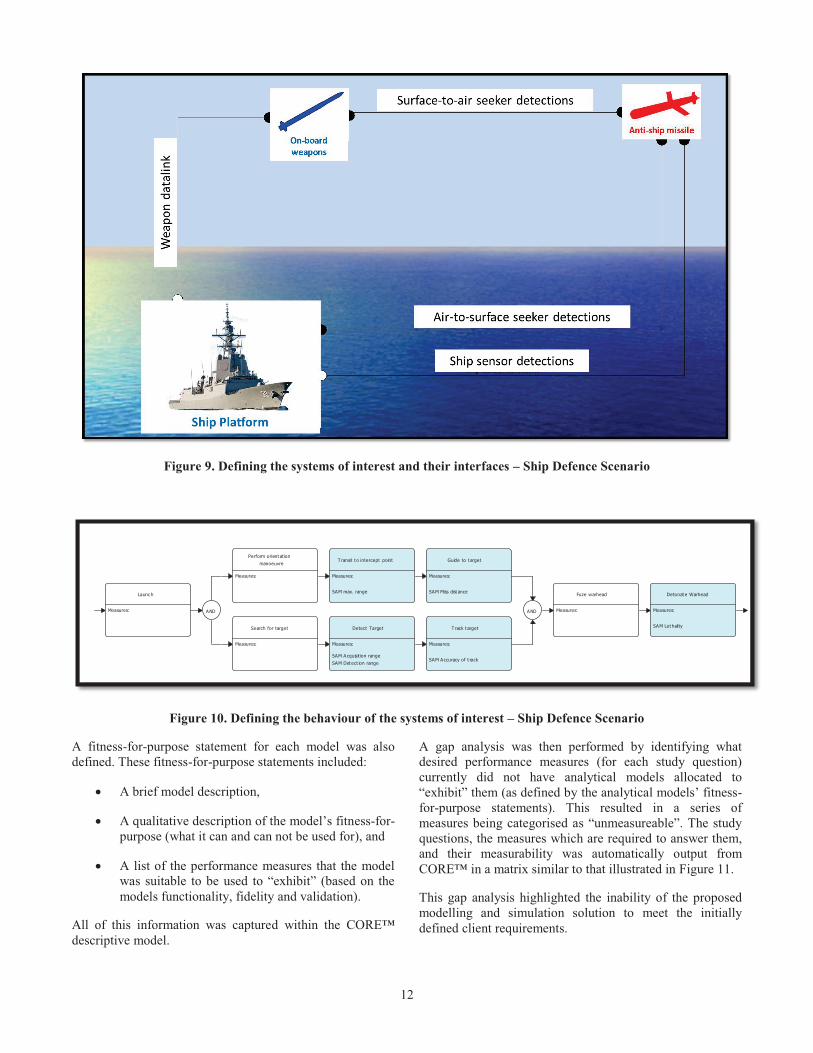
Once the study questions and the desired performance measures were defined, the systems of interest (and how they communicate) were then defined and captured in CORE™ in the form of an OV-1 and OV-2 (see Figure 8 and Figure 9 respectively). This helped scope and bound the problem space, while also providing high level guidance about the types of interfaces that may need to be modelled.
The behaviour of each of the systems of interest was then defined in the form of an OV-5 [17]. The entire weapon “kill chain” was functionally described from initial target detection through to assessing the effect of the weapon. This OV-5 was tailored from an existing OV-5 developed for a previous activity. Figure 10 illustrates an unclassified simplification of the surface-to-air missile “flyout” section of the OV-5 developed as a Functional Flow Block Diagram (FFBD). This helped provide an understanding of how the models were required to behave. The desired performance measures were then allocated to the specific activities in the OV-5 which should produce them (e.g. “SAM Probability of Kill” was allocated to the “detonate warhead” activity). This can be seen in Figure 10.
Once the study requirements were defined (in the form of study questions, performance measures, OV-1, OV-2 and OV-5s), the study team was then able to propose a modelling and simulation solution to try and satisfy those requirements.
Initially, a model audit was performed and all pre-existing, relevant, analytical models were identified (such as sensor models, missile models of the systems of interest etc.). These analytical models were described within the CORE™ descriptive MBSE model and linked to the system elements (as defined in the OV-2) and activities that they could be used to model (as defined in the OV-5). These relationships are summarised in Figure 3. This helped identify any gaps in functionality.
2 SAM – Surface to Air Missile – the defensive weapon used by the ship to defeat the incoming threat missile
Launch
Measures: AND
Perform orient at ion
manoeuvre
Measures:
T ransit t o intercept point
Measures:
SAM max. range
Guide to t arget
Measures:
SAM Miss dist ance
Search for target
Measures:
Detect Target
Measures:
SAM Acquisit ion range
SAM Det ect ion range
T rack t arget
Measures:
SAM Accuracy of t rack
AND
Fuze warhead
Measures:
Detonat e Warhead
Measures:
SAM Let hality


14
through to the top level study questions enabled the study team to have a clear focus at all times. If extra development of an analytical model did not enable it to be used to answer a measure of interest, then the development was not required. Similarly, if it was not possible to produce a desired measure with any of the available analytical models or data, it was clearly identified early and the client was able to be informed.
Improved Credibility – The traceability also enabled the study team to better defend their results. When a particular result of the analysis was “challenged” by an external SME, the study team was able to quickly illustrate the genesis and authority of the data that underpinned the outcome. This sped up the resolution of concerns and improved the credibility of the results.
Improved Communication – The use of an OV-5 to describe the weapon kill chain and the underlying system behaviour improved our communication with the client. The use of such diagrams is becoming increasingly common within Australian Defence and can help with communication with specific Defence clients and SMEs. This has been demonstrated through clients specifically requesting that the analysis be underpinned by such a behavioural description.
Facilitate Gap Analysis – The MBSE tool was able to add value to the overall process through the ability to generate artefacts like the “study question / measure traceability matrix”. This not only helped clearly highlight where the gaps existed, but also provided a succinct way of quantifying those gaps.
User Burden – The clearest challenge with using the WSAF (and any MBSE methodology) is the lack of staff familiarity with the approach and tools. This was a key challenge during this study. Only two members of the study team were familiar with CORE™ and only one was proficient, with the burden of effort in the study definition falling on two staff. If more of the community were familiar with MBSE tools, the use of the WSAF would have a minor overhead in the overall process.
Focus on system behaviour – The MBSE approach focusses on the behaviour of the systems (through the OV-5), rather than the physical systems. This helps prevent the study team from focusing on the physical attributes of the systems (e.g. a new “advanced” missile seeker), instead focusing on how the system will actually perform.
Discussed above, the WSAF approach adds value to MS&A endeavours by mitigating potential risks. However, those applying the WSAF approach need to be cognisant of possible pitfalls. The WSAF approach is a rigorous approach, and therefore comes with additional time and resource costs. Before applying the WSAF, the trade-off between time / resources and MS&A risk should be considered. It is a question of both the complexity of the MS&A problem at hand and the competency of the team undertaking the MS&A. For example, if a highly skilled team was addressing a benign MS&A problem, then a WSAF-like approach is unlikely to be required.
Once a decision is made to apply the WSAF it should be recognised that information and decisions captured in the
knowledge model are only as good as the input to the MS&A project (garbage in equals garbage out). Whilst the objective is that the framework, structure and the query functionality of the WSAF will help identify, and therefore remove errors, consideration should continually be given through the process to the correctness of the knowledge model and the adequacy of the inputs.
CONCLUSIONS This paper described the WSAF methodology using case studies from the DST Group and DRDC. Lessons accumulated by both organisations were discussed, covering the application of MBSE tools and techniques to support weapon and combat system MS&A.
DRDC employed the WSAF to ensure that the study questions being asked by the client were comprehensive and that the problem space was sufficiently explored. Each system’s functionality was systematically analysed in order to identify the questions that must be addressed by a study. By focusing on defining the behaviour model they were able to further decompose the study questions that the client was asking and ensure the right questions were being asked. The WSAF provided a better understanding of the system relationships and decomposition of the system behaviour to allow the analysts to help plan subsequent studies.
DST Group employed the WSAF to categorise the study questions, define the study requirements and perform a structured gap analysis. The WSAF was used to ensure that the impact of the gaps were clearly identified and traceable, while improving communication with the client.
It is concluded that MBSE can be used to provide structure, rigour and traceability to the definition of MS&A requirements for the study of aerospace systems, such as weapons and combat systems. This has been demonstrated through the use of the WSAF across multiple projects over 10 years, performed by both DST Group and DRDC. The case studies described within this paper highlight the flexibility and adaptability of the WSAF as well as the wide range of benefits.
While the WSAF, and MBSE in general, have many benefits when applied to the appropriate studies, they do come with time and resource costs. Before applying MBSE, the trade-off between time / resources and MS&A risk should be considered.
REFERENCES [1] Editors:, R. Fujimoto, S. Cornford, C. Paredis and P.
Zimmerman, "Research Challenges in Modeling & Simulation for Engineering Complex Systems," National Science Foundation (NSF), the National Aeronautics and Space Administration (NASA), the Air Force Office of Scientific Research (AFOSR) and the National Modeling & Simulation Coalition (NMSC), 2016.
[2] K. Robinson and D. Graham, "An Improved Methodology for Analysis of Complex Capability," in Systems Engineering Test and Evaluation Conference,


16
Kevin Robinson has been working in Defence Science and Technology since 1992 after graduating from Cranfield University (UK) with an MSc in Control Systems Design. Initially se joined the UK’s Defence Research Agency (DRA) where he researched a range weapon related science including image
processing, guidance and control and complex systems analysis. He became the technical lead on a number of guided weapon acquisition programmes, predominately the Advanced Short Range Air to Air Missile (ASRAAM). In 2005 he left the UK and joined the Australian Defence Science and Technology Group (DST), where he became the Project Science and Technology Advisor (PSTA) for the JASSM acquisition programme. In early 2011 he became the Group Leader of Weapons Capability Analysis Science and Technology Capability (STC) in Weapons Systems Division, before becoming the Group Leader of Systems Integration and Tactical Networking (SITN STC) in 2014. As the Group Leader of the SITN STC he led research on Resilient Tactical Command and Control Information Management for complex environments. Kevin Robinson has also been an Adjunct Senior Research Fellow at The University of South Australia (2011 to 2014). Since 2006, Kevin Robinson has influenced and contributed to the complex systems design domain through his research interests and the establishment and leadership of INCOSE’s model-based conceptual design working group (MBCD WG). Highlights include the establishment and chairing of Australia’s model-based systems engineering symposium (now in its 5th year), lead technical editor (and contributing author) of INCOSE’s INSIGHT special edition on model-based conceptual design, contribution to Systems Engineering Handbook, receiving INCOSE’s 2013 “sustained performance” award for his leadership of the MBCD WG and his keynote at INCOSE’s International Symposium in 2016.

DOCUMENT CONTROL DATA (Security markings for the title, abstract and indexing annotation must be entered when the document is Classified or Designated)
1. ORIGINATOR (The name and address of the organization preparing the document. Organizations for whom the document was prepared, e.g., Centre sponsoring a contractor's report, or tasking agency, are entered in Section 8.) DRDC – Valcartier Research Centre Defence Research and Development Canada 2459 route de la Bravoure Quebec (Quebec) G3J 1X5 Canada
2a. SECURITY MARKING (Overall security marking of the document including special supplemental markings if applicable.)
CAN UNCLASSIFIED
2b. CONTROLLED GOODS
NON-CONTROLLED GOODS DMC A
3. TITLE (The complete document title as indicated on the title page. Its classification should be indicated by the appropriate abbreviation (S, C or U) in parentheses after the title.) Applying Model-Based System Engineering to Modelling and Simulation Requirements for Weapon Analysis
4. AUTHORS (last name, followed by initials – ranks, titles, etc., not to be used) Power, W.; Jeffrey, A.; Robinson, K.
5. DATE OF PUBLICATION (Month and year of publication of document.) December 2017
6a. NO. OF PAGES (Total containing information, including Annexes, Appendices, etc.)
16
6b. NO. OF REFS (Total cited in document.)
20
7. DESCRIPTIVE NOTES (The category of the document, e.g., technical report, technical note or memorandum. If appropriate, enter the type of report, e.g., interim, progress, summary, annual or final. Give the inclusive dates when a specific reporting period is covered.) External Literature (P)
8. SPONSORING ACTIVITY (The name of the department project office or laboratory sponsoring the research and development – include address.) DRDC – Valcartier Research Centre Defence Research and Development Canada 2459 route de la Bravoure Quebec (Quebec) G3J 1X5 Canada
9a. PROJECT OR GRANT NO. (If appropriate, the applicable research and development project or grant number under which the document was written. Please specify whether project or grant.)
03db
9b. CONTRACT NO. (If appropriate, the applicable number under which the document was written.)
10a. ORIGINATOR’S DOCUMENT NUMBER (The official document number by which the document is identified by the originating activity. This number must be unique to this document.) DRDC-RDDC-2017-P119
10b. OTHER DOCUMENT NO(s). (Any other numbers which may be assigned this document either by the originator or by the sponsor.)
11a. FUTURE DISTRIBUTION (Any limitations on further dissemination of the document, other than those imposed by security classification.)
Public release
11b. FUTURE DISTRIBUTION OUTSIDE CANADA (Any limitations on further dissemination of the document, other than those imposed by security classification.)

12. ABSTRACT (A brief and factual summary of the document. It may also appear elsewhere in the body of the document itself. It is highly desirable that the abstract of classified documents be unclassified. Each paragraph of the abstract shall begin with an indication of the security classification of the information in the paragraph (unless the document itself is unclassified) represented as (S), (C), (R), or (U). It is not necessary to include here abstracts in both official languages unless the text is bilingual.)
The use of Model-Based Systems Engineering (MBSE) to support the definition of requirements and design of modern complex aerospace systems is becoming increasingly accepted. However, MBSE tools and techniques also have many beneficial applications in the definition of requirements for conceptual modelling, and in the design for modelling, simulation, analysis and implementation of aerospace systems. Engineered systems are achieving unprecedented levels of scale and complexity [1] and, arguably, some of the most complex aerospace systems today are military weapons and combat systems. As a result of this increase in system complexity, modelling and simulation is becoming increasingly important, but also increasingly challenging [1]. To address this, an MBSE based framework, known as the Whole of System Analytical Framework (WSAF) [2], was developed to provide structure, rigour and traceability to the definition of analyses being performed within the Weapons and Combat Systems Division of the Australian Defence Science and Technology Group (DST Group). The WSAF is grounded in standard analysis principles and practises (for example, those described in [3]) but applies MBSE tools and techniques to support the analyst throughout the process [4]. Employing the WSAF, the study definition for the analysis of a weapon system’s performance is achieved by deconstructing the systems of interest into their functional components. This activity considers the weapon “kill chain” from initial target detection through to assessing the effect of the weapon [5], and can include the entire combat system (including third party support platforms). Each system’s functionality is then systematically analysed in order to identify the questions that must be addressed by a study. The modelling, simulation and analysis requirements necessary to answer those questions are then derived [2] [4]. By functionally defining the whole weapon system kill chain, analysts are able to ensure that their analysis is complete and rigorous, while the tools provide the required traceability [4]. As the WSAF has evolved over the last decade, it has incorporated various aspects of the Systems Modelling Language (SysML [6]). This has included the employment of diagrams such as the “internal block diagram”, to define the mathematical modelling architecture, and concepts such as “swim lanes” for activity diagrams, as well as custom views to directly support the analyst. The WSAF has been applied across the Australian defence domain and is utilised by one of DST Group’s partner organisations, Defence Research and Development Canada (DRDC). Between DST Group and DRDC, the WSAF has been employed to define the requirements for the modelling, simulation and analysis of air-to-surface missiles, ship based air and missile defence systems as well as ground-based air and missile defence systems. These analyses have provided advice to Defence clients on technologies and weapon performance assessments, supported tactics development, and contributed to requirements definition for system acquisitions [4] [7] [8] [9]. This paper describes the WSAF methodology using case studies from the DST Group and DRDC. Lessons accumulated by both organisations are discussed, covering the application of MBSE tools and techniques to support weapon and combat system modelling, simulation and analysis for over a decade. ___________________________________________________________________________
13. KEYWORDS, DESCRIPTORS or IDENTIFIERS (Technically meaningful terms or short phrases that characterize a document and could be helpful in cataloguing the document. They should be selected so that no security classification is required. Identifiers, such as equipment model designation, trade name, military project code name, geographic location may also be included. If possible keywords should be selected from a published thesaurus, e.g., Thesaurus of Engineering and Scientific Terms (TEST) and that thesaurus identified. If it is not possible to select indexing terms which are Unclassified, the classification of each should be indicated as with the title.) Model-Based System Engineering, Modeling and Simulation, Weapon Analysis, Whole of System Analytical Framework (WSAF)


![[ENTER CHAPTER TITLE HERE] - cradpdf.drdc …cradpdf.drdc-rddc.gc.ca/PDFS/unc120/p536906_A1b.pdf · To be effective in this pursuit, the Canadian Forces (CF) began a process of ...](https://static.fdocuments.us/doc/165x107/5b9ab49109d3f20b318c1c0c/enter-chapter-title-here-to-be-effective-in-this-pursuit-the-canadian-forces.jpg)


