![á F] - vaillant.pl · 3e DHW 10c 5 2 12d 3 12d 3c 10c 3 12d 12 12a 9j 8e 9h BUS BUS BUS BUS BUS BUS BUS BUS BUS BUS BUS 8c 8f BUS 12d (S9) 8b 3f2 10c 9a FS2 12k2 9c 2 4 33 9k2 12d](https://static.fdocuments.us/doc/165x107/5c69bd9909d3f21a048b9235/a-f-3e-dhw-10c-5-2-12d-3-12d-3c-10c-3-12d-12-12a-9j-8e-9h-bus-bus-bus-bus.jpg)
Application Recommendations REF 542plus · Q12 - bus riser. A typical ... protocol uses a 1 Mb/s...
20
Application Recommendations REF 542plus Application and Setting Guide
Transcript of Application Recommendations REF 542plus · Q12 - bus riser. A typical ... protocol uses a 1 Mb/s...

Application Recommendations REF 542plus
Application and Setting Guide


Application Recommendations
Application and Setting Guide
REF 542plusIssued: 31.08.2007Version: B/29.08.2008
1MRS756405
CopyrightsThe information in this document is subject to change without notice and should not be construed as a commitment by ABB Oy. ABB Oy assumes no responsibility for any errors that may appear in this document.
In no event shall ABB Oy be liable for direct, indirect, special, incidental or consequential damages of any nature or kind arising from the use of this document, nor shall ABB Oy be liable for incidental or consequential damages arising from use of any software or hardware described in this document.
This document and parts thereof must not be reproduced or copied without written permission from ABB Oy, and the contents thereof must not be imparted to a third party nor used for any unauthorized purpose.
The software or hardware described in this document is furnished under a license and may be used, copied, or disclosed only in accordance with the terms of such license.
Copyright © 2008 ABB Oy
All rights reserved.
3
1MRS756405Application Recommendations
Application and Setting Guide
REF 542plus
Q01
Q05Q03
Q07 Q09 Q11
Q02
Q10Q12 Q04
Q08 Q06
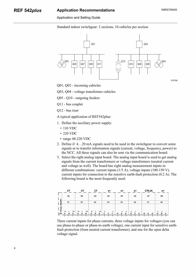
Standard indoor switchgear: 2 sections, 10 cubicles per section.
070790
Q01, Q02 - incoming cubicles
Q03, Q04 - voltage transformer cubicles
Q05 - Q10 - outgoing feeders
Q11 - bus coupler
Q12 - bus riser
A typical application of REF542plus:
1. Define the auxiliary power supply:• 110 VDC• 220 VDC• range 48-220 VDC
2. Define if 4…20 mA signals need to be used in the switchgear to convert some signals or to transfer information signals (current, voltage, frequency, power) to the NCC. All these signals can also be sent via the communication board.
3. Select the right analog input board. The analog input board is used to get analog signals from the current transformers or voltage transformers (neutral current and voltage as well). The board has eight analog measurement inputs in different combinations: current inputs (1/5 A), voltage inputs (100-150 V), current inputs for connection to the sensitive earth-fault protection (0.2 A). The following board is the most frequently used:
Three current inputs for phase currents, three voltage inputs for voltages (you can use phase-to-phase or phase-to-earth voltage), one current input for sensitive earth-fault protection (from neutral current transformer), and one for the open delta voltage signal.
4

1MRS756405 Application Recommendations
Application and Setting Guide
REF 542plus
d2BI1
BI15
BI2
BI16
BI3
BI17
BI4
BI18
BI5
BI19
BI6
BI20
BI7
BI21
BI8
BI22
BI9
BI23
BI10
BI24
BI11
BI25
BI12
BI26
BI13
BI27
BI14
BI28
d2S1
S15
S2
S16
S3
S17
S4
S18 S20 S22 S24 S26 S28
S5
S19
S21 S23 S25 S27
S6
S7
S8 S9
S10
S11
S12 S13 S14
d10
d10
d12
d12
d18
d18
d20
d20
d22
d22
d24
d24
d26
d26
d28
d28
X20
X30
d4d4
d5d5
d8d8
d14
d14
d16
d16
Z2z2
z10
z10
z12
z12
z18
z18
z20
z20
z22
z22
z24
z24
z26
z26
z28
z28
z4z4
z5z5
z8z8
z14
z14
z16
z16
++
++
++
++
++
++
++
++
++
++
++
++
++
++
__
__
__
__
__
__
__
__
__
__
__
__
__
__
BO1
BO3
BO4
BO5
BO6
BO7
BO8
WD1
BO2
X21 d2 d6 z8 d10
d14
z10
z14
d20
z20
z26
d28
z32
z4d4 d8 z6 d12
d16
d18
z18
d24
z28
d30
z12
z16
d22
z22
z24
d26
z30
z2
4. Select the binary input-output board. You can select the board for 110 VDC or 220 VDC and verify whether is it necessary to use a static channel for the impulse signals.
The most often used boards are the one for 220 VDC and the following board:
Binary I/O3 - 80…250 V/143 V Standard. It has 14 binary inputs and 8 output relays. One output has an internal pulse generator to monitor the connected circuit (usually used for Trip Coil Supervision, TCS). The voltage input threshold is 143 V (according to GOST).
For incomings and bus couplers, it is recommended to use 3 I/O boards to have an option for designing a complex logical scheme. For the outgoings, it is recommended to use two boards.
5. Define the communication board (if needed). REF 542plus has an embedded WEB server. In addition, the MODBUS TCP communication protocol can be used via the Ethernet RJ 45 interface. An additional multi-communication system can be built using the following protocols:
• MODBUS RTU RS485 (used for SPA as well)• MODBUS RTU Fiber Optic with ST connectors (used for SPA as well)• SPA Plastic Fiber version snap-in connectors• SPA Glass Fiber with SMA connectors• SPA Glass Fiber with ST connectors• COM-L (LON - LAG 1.4)
5
1MRS756405Application Recommendations
Application and Setting Guide
REF 542plus
• COM-I (IEC 60870-5-103)• Ethernet module for IEC 61850
The difference between the communication systems is the topology, the amount of devices, and the SCADA system of the NCC.
The most common protocol is the standard MODBUS RTU (baud rate 19.2-76.8 kb/s). Connetion to a third party communication system is therefore possible. This protocol has two interfaces: optical (ST connector) and electrical (RS485).
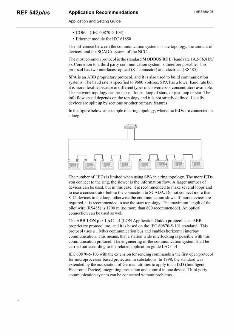
SPA is an ABB proprietary protocol, and it is also used to build communication systems. The baud rate is specified to 9600 kbit/sec. SPA has a lower baud rate but it is more flexible because of different types of converters or concentrators available. The network topology can be star of loops, loop of stars, or just loop or star. The info flow speed depends on the topology and it is not strictly defined. Usually, devices are split up by sections or other primary features.
In the figure below, an example of a ring topology, where the IEDs are connected in a loop.
The number of IEDs is limited when using SPA in a ring topology. The more IEDs you connect to the ring, the slower is the information flow. A larger number of devices can be used, but in this case, it is recommended to make several loops and to use a concentrator before the connection to SCADA. Do not connect more than 8-12 devices to the loop, otherwise the communication slows. If more devices are required, it is recommended to use the start topology. The maximum length of the pilot wire (RS485) is 1200 m (no more than 800 recommended). An optical connection can be used as well.
The ABB LON per LAG 1.4 (LON Application Guide) protocol is an ABB proprietary protocol too, and it is based on the IEC 60870-5-101 standard. This protocol uses a 1 Mb/s communication bus and enables horizontal interbay communication. This means, that a station wide interlocking is possible with this communication protocol. The engineering of the communication system shall be carried out according to the related application guide LAG 1.4.
IEC 60870-5-103 with the extension for sending commands is the first open protocol for microprocessor based protection in substations. In 1998, the standard was extended by the association of German utilities to apply to an IED (Intelligent Electronic Device) integrating protection and control in one device. Third party communication system can be connected without problems.
6
1MRS756405 Application Recommendations
Application and Setting Guide
REF 542plus
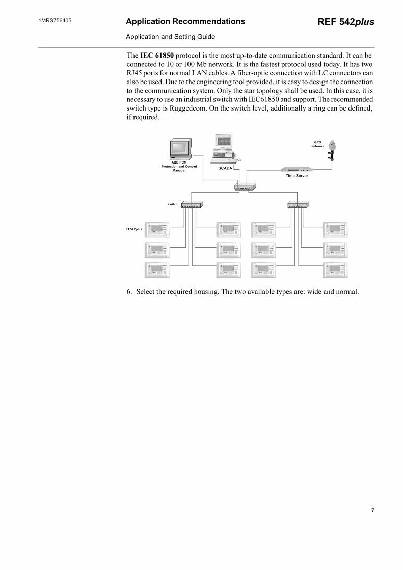
The IEC 61850 protocol is the most up-to-date communication standard. It can be connected to 10 or 100 Mb network. It is the fastest protocol used today. It has two RJ45 ports for normal LAN cables. A fiber-optic connection with LC connectors can also be used. Due to the engineering tool provided, it is easy to design the connection to the communication system. Only the star topology shall be used. In this case, it is necessary to use an industrial switch with IEC61850 and support. The recommended switch type is Ruggedcom. On the switch level, additionally a ring can be defined, if required.
6. Select the required housing. The two available types are: wide and normal.
7
1MRS756405Application Recommendations
Application and Setting Guide
REF 542plus
ca. 70 261,5
M4
106,3
140 1233
185
106,3
244,8
10 18233,5
M4
75,5
75,5
? 0,1
? 0,1?0,1
?0,1
?0,1
?0,1
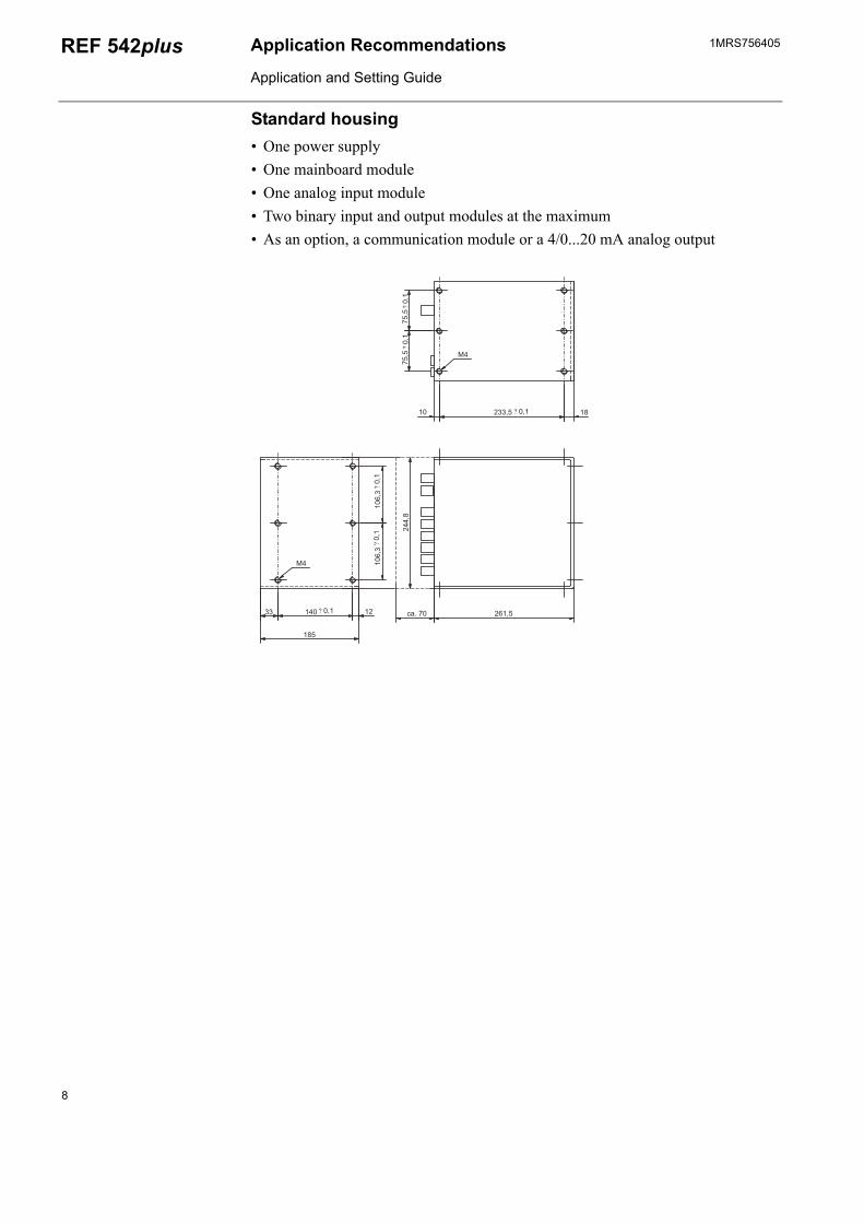
Standard housing• One power supply• One mainboard module• One analog input module• Two binary input and output modules at the maximum• As an option, a communication module or a 4/0...20 mA analog output
8

1MRS756405 Application Recommendations
Application and Setting Guide
REF 542plus
M4
106,3
184 1233
229
106,3
244,8
ca. 70 261,5
97,5
97,5
10 233,5 18
M4
? 0,1
? 0,1
?0,1
?0,1
?0,1
?0,1
Wide housing• One power supply• One mainboard module• One analog input module• Three binary input and output modules at the maximum• As an option, a communication module• As an option, a 4...20 mA analog input module or a 4/0...20 mA analog output
module
7. Select an HMI for the protection. Select the voltage level for the power supply: 48…110 VDC or 110…220 VDC, and select if a protection cover is needed for the LCD. A typical choice is HMI V5 110…220 VDC without a cover.
8. Selection of functionality level:
Table 1.1 Functionality levels of REF 542plus
ANSI CODE
Protection functions for REF542plus
Basic Low Basic Multi Low Multi Differential Distance Hsts
68 Prot Inrush current blocking
x x x x x x x
68 Prot Inrush harmonic x x x x x x x51 Prot Non-directional
overcurrent IDMTx x x x x x x
51 Prot Non-directional overcurrent low
x x x x x x x
51 Prot Non-directional overcurrent high
x x x x x x x
9
1MRS756405Application Recommendations
Application and Setting Guide
REF 542plus
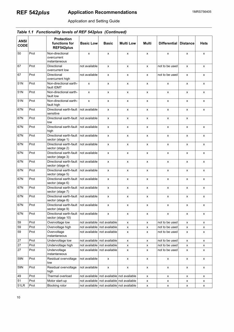
50 Prot Non-directional overcurrent instantaneous
x x x x x x x
67 Prot Directional overcurrent low
not available x x x not to be used x x
67 Prot Directional overcurrent high
not available x x x not to be used x x
51N Prot Non-directional earth-fault IDMT
x x x x x x x
51N Prot Non-directional earth-fault low
x x x x x x x
51N Prot Non-directional earth-fault high
x x x x x x x
67N Prot Directional earth-fault sensitive
not available x x x x x x
67N Prot Directional earth-fault low
not available x x x x x
67N Prot Directional earth-fault high
not available x x x x x x
67N Prot Directional earth-fault sector (stage 1)
not available x x x x x x
67N Prot Directional earth-fault sector (stage 2)
not available x x x x x x
67N Prot Directional earth-fault sector (stage 3)
not available x x x x x x
67N Prot Directional earth-fault sector (stage 4)
not available x x x x x x
67N Prot Directional earth-fault sector (stage 5)
not available x x x x x x
67N Prot Directional earth-fault sector (stage 6)
not available x x x x x x
67N Prot Directional earth-fault sector (stage 7)
not available x x x x x x
67N Prot Directional earth-fault sector (stage 8)
not available x x x x x x
67N Prot Directional earth-fault sector (stage 9)
not available x x x x x x
67N Prot Directional earth-fault sector (stage 10)
not available x x x x x x
59 Prot Overvoltage low not available not available x x not to be used x x59 Prot Overvoltage high not available not available x x not to be used x x59 Prot Overvoltage
instantaneousnot available not available x x not to be used x x
27 Prot Undervoltage low not available not available x x not to be used x x27 Prot Undervoltage high not available not available x x not to be used x x27 Prot Undervoltage
instantaneousnot available not available x x not to be used x x
59N Prot Residual overvoltage low
not available x x x x x x
59N Prot Residual overvoltage high
not available x x x x x x
49 Prot Thermal overload not available not available not available x x x x51 Prot Motor start-up not available not available not available x x x x51LR Prot Blocking rotor not available not available not available x x x x
Table 1.1 Functionality levels of REF 542plus (Continued)
ANSI CODE
Protection functions for REF542plus
Basic Low Basic Multi Low Multi Differential Distance Hsts
10

1MRS756405 Application Recommendations
Application and Setting Guide
REF 542plus
66 Prot Number of starts not available not available not available x x x x21+79 Prot Distance not available not available not available not available not to be used x x87 Prot Transformer
differentialnot available not available not available not available x not to be
usednot to be used
87N Prot Restricted Earth-Fault (low impedance)
not available not available not available not available x x x
46 Prot (CNeg-PhaseSe-quence)
Unbalanced load not available not available x x x x x
32 Prot Directional power not available not available not available x not to be used x x37 Prot Low load not available not available not available x x x81 Prot Frequency
supervisionnot available not available not available x not to be used x x
81 Prot Frequency protection (stage 1, network 1)
not available not available not available x not to be used x x
81 Prot Frequency protection (stage 2, network 1)
not available not available not available x not to be used x x
81 Prot Frequency protection (stage 3, network 1)
not available not available not available x not to be used x x
81 Prot Frequency protection (stage 4, network 1)
not available not available not available x not to be used x x
81 Prot Frequency protection (stage 5, network 1)
not available not available not available x not to be used x x
81 Prot Frequency protection (stage 6, network 1)
not available not available not available x not to be used x x
81 Prot Frequency protection (stage 1, network 2)
not available not available not available x not to be used x x
81 Prot Frequency protection (stage 2, network 2)
not available not available not available x not to be used x x
81 Prot Frequency protection (stage 3, network 2)
not available not available not available x not to be used x x
81 Prot Frequency protection (stage 4, network 2)
not available not available not available x not to be used x x
81 Prot Frequency protection (stage 5, network 2)
not available not available not available x not to be used x x
81 Prot Frequency protection (stage 6, network 2)
not available not available not available x not to be used x x
25 Prot Synchronism check x x x x not to be used x x79 Primi Autorecloser x x x x not to be used x
Primi Power factor controller not available not available not available x not to be used x xProt Switching resonance
protectionnot available not available not available x not to be used x x
Primi High harmonic protection
not available not available not available x x x
Primi Fault recorder x x x x x x x
Table 1.1 Functionality levels of REF 542plus (Continued)
ANSI CODE
Protection functions for REF542plus
Basic Low Basic Multi Low Multi Differential Distance Hsts
11
1MRS756405Application Recommendations
Application and Setting Guide
REF 542plus
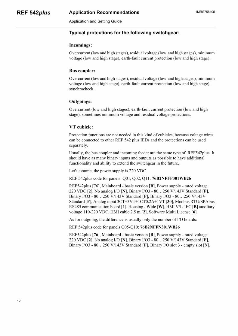
Typical protections for the following switchgear:
Incomings:Overcurrent (low and high stages), residual voltage (low and high stages), minimum voltage (low and high stage), earth-fault current protection (low and high stage).
Bus coupler:Overcurrent (low and high stages), residual voltage (low and high stages), minimum voltage (low and high stage), earth-fault current protection (low and high stage), synchrocheck.
Outgoings:Overcurrent (low and high stages), earth-fault current protection (low and high stage), sometimes minimum voltage and residual voltage protections.
VT cubicle:Protection functions are not needed in this kind of cubicles, because voltage wires can be connected to other REF 542 plus IEDs and the protections can be used separately.
Usually, the bus coupler and incoming feeder are the same type of REF542plus. It should have as many binary inputs and outputs as possible to have additional functionality and ability to extend the switchgear in the future.
Let's assume, the power supply is 220 VDC.
REF 542plus code for panels: Q01, Q02, Q11: 76B2NFFF301WB26
REF542plus [76], Mainboard - basic version [B], Power supply - rated voltage 220 VDC [2], No analog I/O [N], Binary I/O3 - 80…250 V/143V Standard [F], Binary I/O3 - 80…250 V/143V Standard [F], Binary I/O3 - 80…250 V/143V Standard [F], Analog input 3CT+3VT+1CT0.2A+1VT [30], Modbus RTU/SPAbus RS485 communication board [1], Housing - Wide [W], HMI V5 - IEC [B] auxiliary voltage 110-220 VDC, HMI cable 2.5 m [2], Software Multi License [6].
As for outgoing, the difference is usually only the number of I/O boards:
REF 542plus code for panels Q05-Q10: 76B2NFFN301WB26
REF542plus [76], Mainboard - basic version [B], Power supply - rated voltage 220 VDC [2], No analog I/O [N], Binary I/O3 - 80…250 V/143V Standard [F], Binary I/O3 - 80…250 V/143V Standard [F], Binary I/O slot 3 - empty slot [N],
12

1MRS756405 Application Recommendations
Application and Setting Guide
REF 542plus
Analog input 3CT+3VT+1CT0.2A+1VT [30], Modbus RTU/SPAbus RS485 communication board [1], Housing - Wide [W], HMI V5 - IEC [B] auxiliary voltage 110-220 VDC, HMI cable 2.5 m [2], Software Multi License [6].
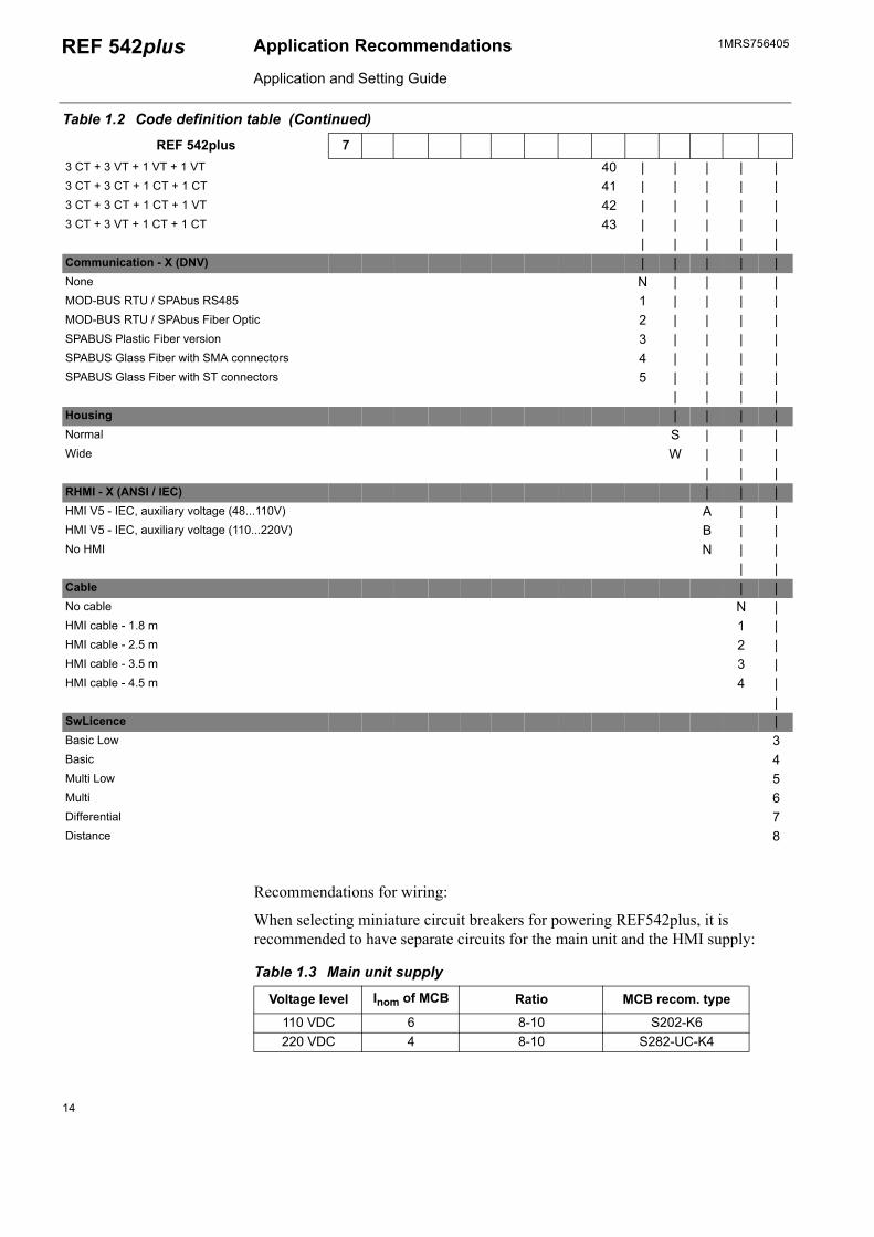
Table 1.2 Code definition table
REF 542plus 7| | | | | | | | | | | | |
Operations field | | | | | | | | | | | | |Standard 6 | | | | | | | | | | | |
| | | | | | | | | | | |Mainboard | | | | | | | | | | | |Basic B | | | | | | | | | | |Standard S | | | | | | | | | | |Full F | | | | | | | | | | |
| | | | | | | | | | |Power supply | | | | | | | | | | |Rated voltage 110 VDC 1 | | | | | | | | | |Rated voltage 220 VDC 2 | | | | | | | | | |Wide range Voltage 48 to 220 VDC 3 | | | | | | | | | |
| | | | | | | | | |Analog - Input or Out | | | | | | | | | |No Analog I/O N | | | | | | | | |Analog Input board 4..20 mA A | | | | | | | | |Analog Output board 4..20mA B | | | | | | | | |
| | | | | | | | |Binary IO Slot 1 | | | | | | | | |Binary I/O3 - 80..250 V/59V - Standard 9 | | | | | | | |Binary I/O3 - 80..250 V/59V - with Static Channel A | | | | | | | |Binary I/O3 - 80..250 V/143V - Standard F | | | | | | | |Binary I/O3 - 80..250 V/143V - with Static Channel G | | | | | | | |
| | | | | | | | |Binary IO Slot 2 | | | | | | | | |None NBinary I/O3 - 80..250 V/59V - Standard 9 | | | | | | |Binary I/O3 - 80..250 V/59V - with Static Channel F | | | | | | |Binary I/O3 - 80..250 V/143V - Standard A | | | | | | |Binary I/O3 - 80..250 V/143V - with Static Channel G | | | | | | |
| | | | | | |Binary IO Slot 3 N | | | | | |Binary I/O3 - 80..250 V/59V - Standard 9 | | | | | |Binary I/O3 - 80..250 V/59V - with Static Channel A | | | | | |Binary I/O3 - 80..250 V/143V - Standard F | | | | | |Binary I/O3 - 80..250 V/143V - with Static Channel G | | | | | |
| | | | | |Analog Input XX: | | | | | |3 CT + 3 VT + 1 CT 0.2A + 1 VT 30 | | | | |3 VT + 3 VT + 1 CT 0.2A + 1 CT 0.2A 31 | | | | |3 CT + 3 CT + 1 CT 0.2A + 1 VT 33 | | | | |3 CT + 3 VY + 1 CT + 1 VT 36 | | | | |3 CT + 3 VT + 1 CT 0.2A + 1 CT 0.2A 39 | | | | |
13
1MRS756405Application Recommendations
Application and Setting Guide
REF 542plus
Recommendations for wiring:
When selecting miniature circuit breakers for powering REF542plus, it is recommended to have separate circuits for the main unit and the HMI supply:
Table 1.3 Main unit supply
Voltage level Inom of MCB Ratio MCB recom. type
110 VDC 6 8-10 S202-K6220 VDC 4 8-10 S282-UC-K4
3 CT + 3 VT + 1 VT + 1 VT 40 | | | | |3 CT + 3 CT + 1 CT + 1 CT 41 | | | | |3 CT + 3 CT + 1 CT + 1 VT 42 | | | | |3 CT + 3 VT + 1 CT + 1 CT 43 | | | | |
| | | | |Communication - X (DNV) | | | | |None N | | | |MOD-BUS RTU / SPAbus RS485 1 | | | |MOD-BUS RTU / SPAbus Fiber Optic 2 | | | |SPABUS Plastic Fiber version 3 | | | |SPABUS Glass Fiber with SMA connectors 4 | | | |SPABUS Glass Fiber with ST connectors 5 | | | |
| | | |Housing | | | |Normal S | | |Wide W | | |
| | |RHMI - X (ANSI / IEC) | | |HMI V5 - IEC, auxiliary voltage (48...110V) A | |HMI V5 - IEC, auxiliary voltage (110...220V) B | |No HMI N | |
| |Cable | |No cable N |HMI cable - 1.8 m 1 |HMI cable - 2.5 m 2 |HMI cable - 3.5 m 3 |HMI cable - 4.5 m 4 |
|SwLicence |Basic Low 3Basic 4Multi Low 5Multi 6Differential 7Distance 8
Table 1.2 Code definition table (Continued)
REF 542plus 7
14
1MRS756405 Application Recommendations
Application and Setting Guide
REF 542plus
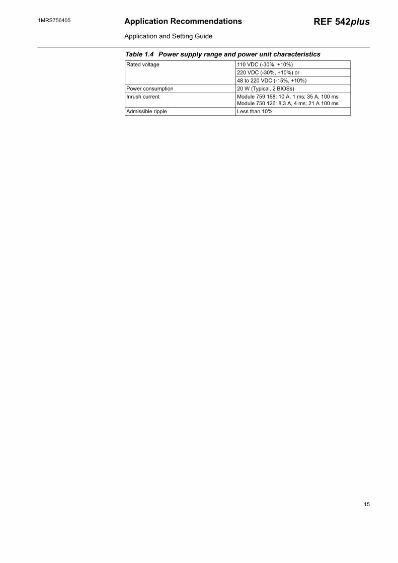
Table 1.4 Power supply range and power unit characteristicsRated voltage 110 VDC (-30%, +10%)
220 VDC (-30%, +10%) or48 to 220 VDC (-15%, +10%)
Power consumption 20 W (Typical, 2 BIOSs) Inrush current Module 759 168: 10 A, 1 ms; 35 A, 100 ms
Module 750 126: 8.3 A, 4 ms; 21 A 100 msAdmissible ripple Less than 10%
15
1MRS756405Application Recommendations
Application and Setting Guide
REF 542plus
10 14 18
multiples of rated current
Seco
nds
Min
utes
1 1.5 2 3 4 5 6 8 10 15 20 30
0.01
0.02
0.040.06
0.1
0.2
0.40.6
1
2
46
10
20
401
2
46
10
20
4060
120
1.05
1.2
Z K
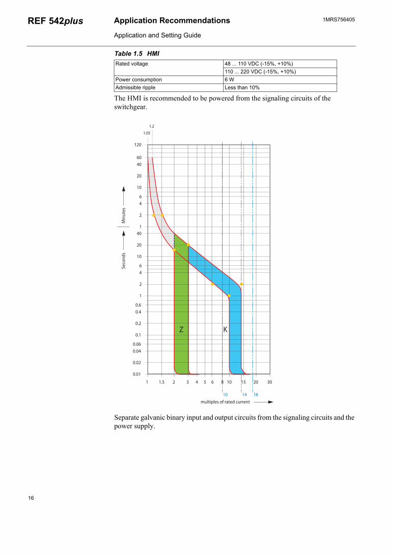
Table 1.5 HMIRated voltage 48 ... 110 VDC (-15%, +10%)
110 ... 220 VDC (-15%, +10%)Power consumption 6 WAdmissible ripple Less than 10%
The HMI is recommended to be powered from the signaling circuits of the switchgear.
Separate galvanic binary input and output circuits from the signaling circuits and the power supply.
16


ADP.FFTeFw
1MR
S75
6405
EN
08.
2008
BB Oyistribution Automation O. Box 699 I-65101 Vaasa INLANDl. +358 10 22 11
ax. +358 10 224 1094ww.abb.com/substationautomation