Application of X-Shaped CFRP Ropes for Structural ...
15
fibers Article Application of X-Shaped CFRP Ropes for Structural Upgrading of Reinforced Concrete Beam–Column Joints under Cyclic Loading–Experimental Study Emmanouil Golias, Adamantis G. Zapris, Violetta K. Kytinou , Mourhat Osman, Michail Koumtzis, Danai Siapera, Constantin E. Chalioris * and Chris G. Karayannis Citation: Golias, E.; Zapris, A.G.; Kytinou, V.K.; Osman, M.; Koumtzis, M.; Siapera, D.; Chalioris, C.E.; Karayannis, C.G. Application of X-Shaped CFRP Ropes for Structural Upgrading of Reinforced Concrete Beam–Column Joints under Cyclic Loading–Experimental Study. Fibers 2021, 9, 42. https://doi.org/ 10.3390/fib9070042 Academic Editor: Akanshu Sharma Received: 8 May 2021 Accepted: 28 June 2021 Published: 1 July 2021 Publisher’s Note: MDPI stays neutral with regard to jurisdictional claims in published maps and institutional affil- iations. Copyright: © 2021 by the authors. Licensee MDPI, Basel, Switzerland. This article is an open access article distributed under the terms and conditions of the Creative Commons Attribution (CC BY) license (https:// creativecommons.org/licenses/by/ 4.0/). Laboratory of Reinforced Concrete and Seismic Design of Structures, Civil Engineering Department, School of Engineering, Democritus University of Thrace, 67100 Xanthi, Greece; [email protected] (E.G.); [email protected] (A.G.Z.); [email protected] (V.K.K.); [email protected] (M.O.); [email protected] (M.K.); [email protected] (D.S.); [email protected] (C.G.K.) * Correspondence: [email protected]; Tel.: +30-25-4107-9632 Abstract: The effectiveness of externally applied fiber-reinforced polymer (FRP) ropes made of carbon fibers in X-shape formation and in both sides of the joint area of reinforced concrete (RC) beam–column connections is experimentally investigated. Six full-scale exterior RC beam–column joint specimens are tested under reverse cyclic deformation. Three of them have been strengthened using carbon FRP (CFRP) ropes that have been placed diagonally in the joint as additional, near surface-mounted reinforcements against shear. Full hysteretic curves, maximum applied load capac- ity, damage modes, stiffness and energy dissipation values per each loading step are presented and compared. Test results indicated that joint sub assemblages with X-shaped CFRP ropes exhibited improved hysteretic behavior and ameliorated performance with respect to the reference speci- mens. The effectiveness and the easy-to-apply character of the presented strengthening technique is also discussed. Keywords: reinforced concrete; carbon FRP ropes; cyclic tests; hysteretic response 1. Introduction In the structural engineering industry, the rehabilitation and seismic upgrade of reinforced concrete (RC) buildings have become a primary concern. Several existing RC frame structures were designed before the modern seismic regulations were developed, or they were merely made to comply to earlier versions of the seismic guidelines [1]. As a result, they have various issues, such as as short longitudinal beam bottom bar embedment lengths, low shear capacity in the beam–column joint, and inadequate or no steel transverse reinforcement in the joint area [2,3]. The brittle failure of improperly reinforced beam–column joints, particularly exterior ones, has already been identified as the primary cause of collapse in multiple structures in recent seismic events around the world [4]. Therefore, over the last twenty years, multiple research studies have been directed towards the rehabilitation/retrofitting of damaged beam–column joints, and various methods for their strengthening have been introduced. One of the first methods for seismically strengthening deficient RC beam–column joints was RC jacketing [5,6]. RC jackets involve the addition of new longitudinal and transversal reinforcement bars and the application of a new extra concrete coating. This leads to an increase in the dimensions of the elements’ cross-sections [7]. While RC jacketing has proven its efficiency to enhance the shear strength of the joints, it also has some serious drawbacks, as the increase in the cross-sectional dimension results in adding weight and enhancing the stiffness of the structural elements [8]. Another main disadvantage of this method is that it implies complex and labor-intensive application procedures [9]. Fibers 2021, 9, 42. https://doi.org/10.3390/fib9070042 https://www.mdpi.com/journal/fibers
Transcript of Application of X-Shaped CFRP Ropes for Structural ...
fibers
Article
Application of X-Shaped CFRP Ropes for Structural Upgradingof Reinforced Concrete Beam–Column Joints under CyclicLoading–Experimental Study
Emmanouil Golias, Adamantis G. Zapris, Violetta K. Kytinou , Mourhat Osman, Michail Koumtzis,Danai Siapera, Constantin E. Chalioris * and Chris G. Karayannis
�����������������
Citation: Golias, E.; Zapris, A.G.;
Kytinou, V.K.; Osman, M.; Koumtzis,
M.; Siapera, D.; Chalioris, C.E.;
Karayannis, C.G. Application of
X-Shaped CFRP Ropes for Structural
Upgrading of Reinforced Concrete
Beam–Column Joints under Cyclic
Loading–Experimental Study. Fibers
2021, 9, 42. https://doi.org/
10.3390/fib9070042
Academic Editor: Akanshu Sharma
Received: 8 May 2021
Accepted: 28 June 2021
Published: 1 July 2021
Publisher’s Note: MDPI stays neutral
with regard to jurisdictional claims in
published maps and institutional affil-
iations.
Copyright: © 2021 by the authors.
Licensee MDPI, Basel, Switzerland.
This article is an open access article
distributed under the terms and
conditions of the Creative Commons
Attribution (CC BY) license (https://
creativecommons.org/licenses/by/
4.0/).
Laboratory of Reinforced Concrete and Seismic Design of Structures, Civil Engineering Department,School of Engineering, Democritus University of Thrace, 67100 Xanthi, Greece; [email protected] (E.G.);[email protected] (A.G.Z.); [email protected] (V.K.K.); [email protected] (M.O.);[email protected] (M.K.); [email protected] (D.S.); [email protected] (C.G.K.)* Correspondence: [email protected]; Tel.: +30-25-4107-9632
Abstract: The effectiveness of externally applied fiber-reinforced polymer (FRP) ropes made ofcarbon fibers in X-shape formation and in both sides of the joint area of reinforced concrete (RC)beam–column connections is experimentally investigated. Six full-scale exterior RC beam–columnjoint specimens are tested under reverse cyclic deformation. Three of them have been strengthenedusing carbon FRP (CFRP) ropes that have been placed diagonally in the joint as additional, nearsurface-mounted reinforcements against shear. Full hysteretic curves, maximum applied load capac-ity, damage modes, stiffness and energy dissipation values per each loading step are presented andcompared. Test results indicated that joint sub assemblages with X-shaped CFRP ropes exhibitedimproved hysteretic behavior and ameliorated performance with respect to the reference speci-mens. The effectiveness and the easy-to-apply character of the presented strengthening technique isalso discussed.
Keywords: reinforced concrete; carbon FRP ropes; cyclic tests; hysteretic response
1. Introduction
In the structural engineering industry, the rehabilitation and seismic upgrade ofreinforced concrete (RC) buildings have become a primary concern. Several existing RCframe structures were designed before the modern seismic regulations were developed, orthey were merely made to comply to earlier versions of the seismic guidelines [1]. As aresult, they have various issues, such as as short longitudinal beam bottom bar embedmentlengths, low shear capacity in the beam–column joint, and inadequate or no steel transversereinforcement in the joint area [2,3].
The brittle failure of improperly reinforced beam–column joints, particularly exteriorones, has already been identified as the primary cause of collapse in multiple structures inrecent seismic events around the world [4]. Therefore, over the last twenty years, multipleresearch studies have been directed towards the rehabilitation/retrofitting of damagedbeam–column joints, and various methods for their strengthening have been introduced.
One of the first methods for seismically strengthening deficient RC beam–columnjoints was RC jacketing [5,6]. RC jackets involve the addition of new longitudinal andtransversal reinforcement bars and the application of a new extra concrete coating. Thisleads to an increase in the dimensions of the elements’ cross-sections [7]. While RC jacketinghas proven its efficiency to enhance the shear strength of the joints, it also has some seriousdrawbacks, as the increase in the cross-sectional dimension results in adding weight andenhancing the stiffness of the structural elements [8]. Another main disadvantage of thismethod is that it implies complex and labor-intensive application procedures [9].
Fibers 2021, 9, 42. https://doi.org/10.3390/fib9070042 https://www.mdpi.com/journal/fibers

Fibers 2021, 9, 42 2 of 15
In the field of the seismic rehabilitation/strengthening of RC and masonry struc-tures, externally applied jackets and overlays with advanced composite materials suchas fiber-reinforced polymers (FRP) and textile-reinforced mortars (TRM) are promisingalternative techniques [10–13]. Applications of externally bonded FRP composites havebeen thoroughly used and studied over the last twenty years because of their advantages,such as easy and quick implementation, resistance to corrosion, and high strength/weightratio [14–17]. The merits of FRP materials in the form of sheets, strips, laminates andjackets to provide a quick to install, easy to apply, safe and reliable strengthening/repairtechnique have been revealed by several researchers. Some researchers have investigatedthe effectiveness of FRP strengthening applications in the overall performance of RCstructures [18–21], while others focused on individual RC elements. There are studiesinvestigating the enhancement of the strength and ductility of RC beams strengthenedwith FRP sheets or laminates [22–25]. Other researchers examined the influence of FRPstrengthening/repairing techniques on the flexural [26] or shear [27,28] behavior of RCbeams. The efficacy of FRP materials in providing extra confinement to RC columns hasalso been proven by several investigations [29–32]. The ability of FRP composites to en-hance the seismic efficiency of damaged RC beam–column joints has been confirmed byvarious experimental studies. Researchers have studied the application of FRP jacketing indeficient exterior [33–36] and interior [37,38] RC joints, while others have compared theapplication of this technique with the conventional RC jacketing method [39].
Besides the many advantages of the FRP rehabilitation method, established FRP con-figurations may require preliminary operations, such as the partial removal of infill wallsor partial slab demolition, which are expensive and may also disrupt the functionalityin certain parts of the building. When referring to structure restoration after a seismicincident, this aspect is less important, since most structures are totally or partially nonfunc-tional in these situations. On the other hand, when building retrofitting is planned as aprecaution against seismic damage, it must be considered that owners always comparethe advantages of a strengthening operation, which cannot be instantly evaluated, againstthe fact that certain sections of the building will remain inaccessible for the period of thestrengthening procedures.
These observations have presented new challenges in creating novel enhancementtechniques that can be externally applied to the structure or with a low level of disturbance.A recent strengthening method that was proposed by the authors of [40,41] incorporatesthe aforementioned requirements. This novel technique includes the use of FRP ropes,either as near-surface mounting (NSM) or as embedded through section (ETS) in the jointarea, and this appears to be a promising retrofitting scheme. FRP ropes were developed toact as an anchorage for the application of FRP sheets to delay the sheet’s debonding fromthe concrete surface. So far, there are only a few studies in the literature implementing FRPrope anchoring systems in beams, columns and beam–column joint connections [42–45].
In recent years, however, a few studies have also indicated that the application of FRPropes as an individual strengthening technique is also very effective. In these studies, FRPropes have been used to retrofit the support region of RC beams tested under cyclic load-ing [46], as reinforcement for the shear strengthening of T-beams [47] and rectangular deepbeams [48], for the torsional strengthening of RC beams [49], to provide extra confinementin columns [50], and also for the strengthening of joints [40]. However, due to the limitednumber of studies, further research on the efficacy of FRP ropes as a strengthening methodis required. Further, it is noted that the fatigue life estimation of the retrofitted structuralmembers and their components (concrete, steel reinforcement and especially FRP ropes)under different loading conditions has not been investigated. Recent studies highlightedthe importance of the low-cycle fatigue behavior of steel structural members subjected tostatic and transient dynamic loads [51,52].
The current study aims to further investigate the effectiveness of the use of carbonFRP (CFRP) rope application as a strengthening method in deficient RC beam–columnjoints subjected to seismic loads. Six specimens were experimentally investigated; three

Fibers 2021, 9, 42 3 of 15
of them were reference specimens with inadequate shear reinforcement in the joint areaand three were strengthened with CFRP ropes installed as NSM reinforcement. All theexamined joint specimens were tested under reversal imposed cyclic deformations with thesame loading history. The contribution of the proposed strengthening method to the joint’sload bearing capacity was then evaluated and examined at every loading step, in relationto the reference specimens. The experimental values of ultimate applied load, stiffnessand energy dissipation are also compared and discussed. The suggested strengtheningarrangements of the additional fiber composite reinforcement have been designed in a wayas to reduce the degree of disturbance caused by their in-situ application in realistic RCframe structures.
2. Experimental Program
The efficacy of using CFRP ropes as a strengthening method in deficient RC jointssubjected to seismic loads was experimentally investigated. Six full-size specimens of beam–column joints (scale 1:1) were constructed and tested under the same cyclic loading. Threeof the six specimens examined were reference specimens (JA0, JA1, and JB1), and three ofthem were strengthened with CFRP ropes installed as near-surface-mounted reinforcement(JA0Fxb, JA1Fxb, JB1Fx). Specimens JA0 and JA1 were designed so that damage occurspredominantly in the beam region, while specimen JB1 was designed so that damagedevelops mainly in the joint.
2.1. Geometry and Reinforcement Characteristics of the Specimens
The geometric characteristics were common for all six specimens. The total length ofthe column was 3000 mm with a cross-section of 350/250 mm, and the total length of thebeam was 1875 mm with a 350/250 mm cross-section, respectively. All specimens had four14 mm diameter longitudinal bars in the column, one at each angle. All specimens hadfour longitudinal bars with a diameter of 12 mm placed on the top and bottom sides of thebeam, except for JB1 and JB1Fxb, which had bars with a diameter of 14 mm. As transversereinforcement, stirrups with a diameter of 8 mm per 100 mm were installed on both thecolumn and the beam. The specimens JA0 and JA0Fxb had no stirrups in the joint area,while the others had one stirrup with an 8 mm diameter (Figure 1). The clean cover of bothbeams and columns in all tested specimens was 25 mm.
Fibers 2021, 9, x FOR PEER REVIEW 3 of 16
Recent studies highlighted the importance of the low-cycle fatigue behavior of steel structural members subjected to static and transient dynamic loads [51,52].
The current study aims to further investigate the effectiveness of the use of carbon FRP (CFRP) rope application as a strengthening method in deficient RC beam–column joints subjected to seismic loads. Six specimens were experimentally investigated; three of them were reference specimens with inadequate shear reinforcement in the joint area and three were strengthened with CFRP ropes installed as NSM reinforcement. All the examined joint specimens were tested under reversal imposed cyclic deformations with the same loading history. The contribution of the proposed strengthening method to the joint’s load bearing capacity was then evaluated and examined at every loading step, in relation to the reference specimens. The experimental values of ultimate applied load, stiffness and energy dissipation are also compared and discussed. The suggested strengthening arrangements of the additional fiber composite reinforcement have been designed in a way as to reduce the degree of disturbance caused by their in-situ applica-tion in realistic RC frame structures.
2. Experimental Program The efficacy of using CFRP ropes as a strengthening method in deficient RC joints
subjected to seismic loads was experimentally investigated. Six full-size specimens of beam–column joints (scale 1:1) were constructed and tested under the same cyclic load-ing. Three of the six specimens examined were reference specimens (JA0, JA1, and JB1), and three of them were strengthened with CFRP ropes installed as near-surface-mounted reinforcement (JA0Fxb, JA1Fxb, JB1Fx). Specimens JA0 and JA1 were designed so that damage occurs predominantly in the beam region, while specimen JB1 was designed so that damage develops mainly in the joint.
2.1. Geometry and Reinforcement Characteristics of the Specimens The geometric characteristics were common for all six specimens. The total length of
the column was 3000 mm with a cross-section of 350/250 mm, and the total length of the beam was 1875 mm with a 350/250 mm cross-section, respectively. All specimens had four 14 mm diameter longitudinal bars in the column, one at each angle. All specimens had four longitudinal bars with a diameter of 12 mm placed on the top and bottom sides of the beam, except for JB1 and JB1Fxb, which had bars with a diameter of 14 mm. As transverse reinforcement, stirrups with a diameter of 8 mm per 100 mm were installed on both the column and the beam. The specimens JA0 and JA0Fxb had no stirrups in the joint area, while the others had one stirrup with an 8 mm diameter (Figure 1). The clean cover of both beams and columns in all tested specimens was 25 mm.
Figure 1. Reinforcement of the full-scale exterior beam–column joint specimen JA0.
Figure 1. Reinforcement of the full-scale exterior beam–column joint specimen JA0.
Along with conventional reinforcement, CFRP ropes of 6 mm diameter were appliedexternally in an X-shape at each side of the specimen’s joint area in the strengthenedspecimens, while on specimens JA0FXb and JA1FXb, besides the X-shape rope applicationin the joint area, CFRP ropes were also applied at each side on the top and bottom of

Fibers 2021, 9, 42 4 of 15
the surrounding beam. Table 1 also includes details about the reinforcement and thestrengthening of the specimens.
Table 1. Geometrical and reinforcement characteristics of the tested exterior beam–column joint specimens.
NameJoint Area Beam Geometry and Reinforcement Column Geometry and
Reinforcement
Steel CFRP Rope 1 Cross-Section Steel CFRP Rope 1 Cross-Section Steel
JA0 - -{350 × 250}
4∅12 up4∅12 bot.∅8/100
-{350 × 250} 4∅14
∅8/100JA0Fxb - 2XF 2F up2F bot.
JA1 ∅8 -{350 × 250}
4∅12 up4∅12 bot.∅8/100
-{350 × 250} 4∅14
∅8/100JA1Fxb ∅8 2XF 2F up2F bot.
JB1 ∅8 -{350 × 250}
4∅14up4∅14 bot.∅8/100
-{350 × 250} 4∅14
∅8/100JB1Fx ∅8 2XF -
1 CFRP rope’s cross-section area > 28 mm2, according to manufacturer’s data.
2.2. Materials
In order to determine the compressive strength of the concrete used, supplementarycompression tests of six 150 × 300 mm cylinders were also carried out. The mean values ofthe compressive strength of concrete were fcm = 34 MPa. The steel reinforcement for bothlongitudinal and transverse reinforcement had a mean yield strength equal to fy = 550 MPa.The CFRP rope (SikaWrap® FX-50 C) that was used for the specimens was a bundle ofunidirectional carbon fibers with tensile strength equal to 4000 MPa, modulus of elasticityequal to 240 GPa and cross-section area > 28 mm2, according to manufacturer’s data. Twotypes of epoxy resins were used, resin type A (Sikadur®-52) for the impregnation of dryfibers and type B (Sika AnchorFix®-3+) for the anchorage of the system.
2.3. Application of the X-Shaped CFRP Ropes
The strengthening procedure of the specimens as it took place in the reinforcedconcrete laboratory of Democritus University of Thrace is described step by step as follows.
At first, the direction of the carbon fiber ropes was drawn on the surface of thespecimens. With the use of a grinder, the incision of U-shaped notches was made accordingto the dimensions and specifications of the supplier of the material, in order to achieve theencapsulation of the CFRP ropes (Figure 2a).
The dimensions of the notches were 25 mm in depth and 25 mm in width, so thattheir formation took place within the area of the clean cover while still meeting the manu-facturer’s specifications. In case the available cover is smaller than required, a differentinstallation arrangement, such as the application of the CFRP rope as embedded throughthe joint section (ETS) [53], can be selected. During the incision-making process special carewas taken in order to protect the steel bars from being damaged by the grinder. In order toachieve adequate and efficient anchorage of the free ends of the CFRP rope, at the end ofthe beam a vertical opening was drilled in a 90◦ axis relation to the web of the beam with adiameter of 16 mm and length of 80 mm. The notches were cleaned thoroughly of dustand concrete residues (and generally of materials of lower adhesion) using compressed airfrom a special pistol. Epoxy resin type A (Sikadur®-52) was applied in the notches using asmall painting brush (Figure 2b).
The CFRP rope was cut in the required dimensions with scissors after thoroughsaturation of the ropes in epoxy resin according to EN 1504-4 (Figure 2c).
The CFRP ropes were placed into notches and holes under pressure with care in orderto remove air and excessive amounts of resin (Figure 2d).
While the rope was impregnated with resin and was within the effective time windowof the resin, the voids in the notches were filled with epoxy resin type B (Sika AnchorFix®-
Fibers 2021, 9, 42 5 of 15
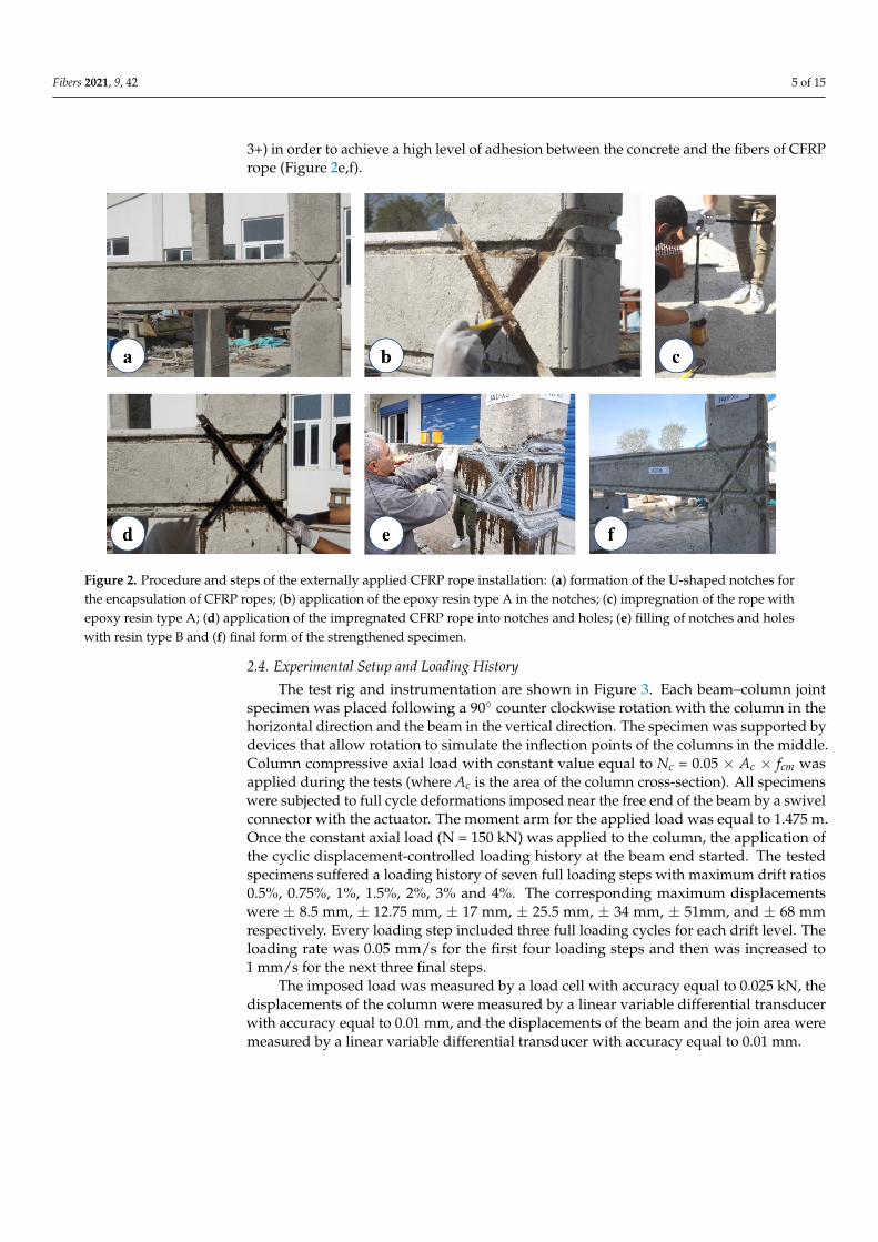
3+) in order to achieve a high level of adhesion between the concrete and the fibers of CFRPrope (Figure 2e,f).
Fibers 2021, 9, x FOR PEER REVIEW 5 of 16
Figure 2. Procedure and steps of the externally applied CFRP rope installation: (a) formation of the U-shaped notches for the encapsulation of CFRP ropes; (b) application of the epoxy resin type A in the notches; (c) impregnation of the rope with epoxy resin type A; (d) application of the impregnated CFRP rope into notches and holes; (e) filling of notches and holes with resin type B and (f) final form of the strengthened specimen.
The dimensions of the notches were 25 mm in depth and 25 mm in width, so that their formation took place within the area of the clean cover while still meeting the manufacturer’s specifications. In case the available cover is smaller than required, a dif-ferent installation arrangement, such as the application of the CFRP rope as embedded through the joint section (ETS) [53], can be selected. During the incision-making process special care was taken in order to protect the steel bars from being damaged by the grinder. In order to achieve adequate and efficient anchorage of the free ends of the CFRP rope, at the end of the beam a vertical opening was drilled in a 90° axis relation to the web of the beam with a diameter of 16 mm and length of 80 mm. The notches were cleaned thoroughly of dust and concrete residues (and generally of materials of lower adhesion) using compressed air from a special pistol. Epoxy resin type A (Sikadur® -52) was applied in the notches using a small painting brush (Figure 2b).
The CFRP rope was cut in the required dimensions with scissors after thorough saturation of the ropes in epoxy resin according to EN 1504-4 (Figure 2c).
The CFRP ropes were placed into notches and holes under pressure with care in order to remove air and excessive amounts of resin (Figure 2d).
While the rope was impregnated with resin and was within the effective time win-dow of the resin, the voids in the notches were filled with epoxy resin type B (Sika An-chorFix® -3+) in order to achieve a high level of adhesion between the concrete and the fibers of CFRP rope (Figure 2e,f).
2.4. Experimental Setup and Loading History The test rig and instrumentation are shown in Figure 3. Each beam–column joint
specimen was placed following a 90° counter clockwise rotation with the column in the horizontal direction and the beam in the vertical direction. The specimen was supported by devices that allow rotation to simulate the inflection points of the columns in the middle. Column compressive axial load with constant value equal to Nc = 0.05 × Ac × fcm was applied during the tests (where Ac is the area of the column cross-section). All specimens were subjected to full cycle deformations imposed near the free end of the
Figure 2. Procedure and steps of the externally applied CFRP rope installation: (a) formation of the U-shaped notches forthe encapsulation of CFRP ropes; (b) application of the epoxy resin type A in the notches; (c) impregnation of the rope withepoxy resin type A; (d) application of the impregnated CFRP rope into notches and holes; (e) filling of notches and holeswith resin type B and (f) final form of the strengthened specimen.
2.4. Experimental Setup and Loading History
The test rig and instrumentation are shown in Figure 3. Each beam–column jointspecimen was placed following a 90◦ counter clockwise rotation with the column in thehorizontal direction and the beam in the vertical direction. The specimen was supported bydevices that allow rotation to simulate the inflection points of the columns in the middle.Column compressive axial load with constant value equal to Nc = 0.05 × Ac × fcm wasapplied during the tests (where Ac is the area of the column cross-section). All specimenswere subjected to full cycle deformations imposed near the free end of the beam by a swivelconnector with the actuator. The moment arm for the applied load was equal to 1.475 m.Once the constant axial load (N = 150 kN) was applied to the column, the application ofthe cyclic displacement-controlled loading history at the beam end started. The testedspecimens suffered a loading history of seven full loading steps with maximum drift ratios0.5%, 0.75%, 1%, 1.5%, 2%, 3% and 4%. The corresponding maximum displacementswere ± 8.5 mm, ± 12.75 mm, ± 17 mm, ± 25.5 mm, ± 34 mm, ± 51mm, and ± 68 mmrespectively. Every loading step included three full loading cycles for each drift level. Theloading rate was 0.05 mm/s for the first four loading steps and then was increased to1 mm/s for the next three final steps.
The imposed load was measured by a load cell with accuracy equal to 0.025 kN, thedisplacements of the column were measured by a linear variable differential transducerwith accuracy equal to 0.01 mm, and the displacements of the beam and the join area weremeasured by a linear variable differential transducer with accuracy equal to 0.01 mm.

Fibers 2021, 9, 42 6 of 15
Fibers 2021, 9, x FOR PEER REVIEW 6 of 16
beam by a swivel connector with the actuator. The moment arm for the applied load was equal to 1.475 m. Once the constant axial load (N = 150 kN) was applied to the column, the application of the cyclic displacement-controlled loading history at the beam end started. The tested specimens suffered a loading history of seven full loading steps with maximum drift ratios 0.5%, 0.75%, 1%, 1.5%, 2%, 3% and 4%. The corresponding maxi-mum displacements were ± 8.5 mm, ± 12.75 mm, ± 17 mm, ± 25.5 mm, ± 34 mm, ± 51mm, and ± 68 mm respectively. Every loading step included three full loading cycles for each drift level. The loading rate was 0.05 mm/s for the first four loading steps and then was increased to 1mm/s for the next three final steps.
Figure 3. Experimental setup and instrumentation of the cyclic testing.
The imposed load was measured by a load cell with accuracy equal to 0.025 kN, the displacements of the column were measured by a linear variable differential transducer with accuracy equal to 0.01 mm, and the displacements of the beam and the join area were measured by a linear variable differential transducer with accuracy equal to 0.01 mm.
3. Test Results and Discussion To determine the effectiveness of the rehabilitation method used, the hysteretic re-
sponse and cracking pattern of each enhanced specimen were compared with the corre-sponding reference specimen. The hysteretic responses and cracking patterns are pre-sented and compared for the first four steps (steps 1, 2, 3, and 4) of the loading, as well as the following three steps (step 5, 6 and 7).
In the first loading step of the reference specimen JA0 (without any stirrups in the joint area), micro-cracking was observed in the beam region. The number and width of cracks in the beam increased as the steps progressed (steps 2 and 3). At the end of step 4, a slight diagonal crack appeared in the joint region. During the first four steps of the strengthened specimen JA0Fxb, cracking was detected in the beam region; however, the number of cracks was smaller, and had reduced width in comparison to the reference
Figure 3. Experimental setup and instrumentation of the cyclic testing.
3. Test Results and Discussion
To determine the effectiveness of the rehabilitation method used, the hysteretic re-sponse and cracking pattern of each enhanced specimen were compared with the corre-sponding reference specimen. The hysteretic responses and cracking patterns are presentedand compared for the first four steps (steps 1, 2, 3, and 4) of the loading, as well as thefollowing three steps (step 5, 6 and 7).
In the first loading step of the reference specimen JA0 (without any stirrups in the jointarea), micro-cracking was observed in the beam region. The number and width of cracksin the beam increased as the steps progressed (steps 2 and 3). At the end of step 4, a slightdiagonal crack appeared in the joint region. During the first four steps of the strengthenedspecimen JA0Fxb, cracking was detected in the beam region; however, the number ofcracks was smaller, and had reduced width in comparison to the reference specimen JA0.The hysteretic response of the specimens indicates that the strengthened specimen had aconsiderably higher load-bearing capacity at each step (Figure 4a).
In order to comprehend some important details concerning the acquired experimentalhysteretic response of the tested specimens, Figure 4b presents the load versus drift curvesat each loading step of the reference specimen JA0. Each step includes three loading cycles.The start point and crack initiation points are noted in the diagram of the first cycle of step 1for both loading directions (positive and negative), as illustrated in Figure 4b. Further, steelyielding due to damage propagation caused by the increased imposed load can also benoted in the diagram of the first cycle of step 4 (Figure 4b). The first cycle at each loadingstep is illustrated in Figure 4 using a green colored line.
As the imposed displacement in the JA0 reference specimen increased (steps 5 and 6),it led to an increase in the crack width at the beginning of the beam (damage concentration),while in step 7 cracking was also observed at the backside of the joint. Although thedamage was concentrated in the beam area, cracks also occurred in the joint body. On theother hand, the imposed displacement increased in the JA0Fxb specimen, resulting in anincreased width of the cracks at the beginning of the beam without significantly affectingthe joint area. The damage of the strengthened specimen was located only in the beam area.

Fibers 2021, 9, 42 7 of 15
In the last steps, the difference in load bearing capacity of the two specimens was reduced,but the strengthened specimen’s behavior was slightly better (Figure 5).
The reference specimens JA1 and JA0 and the strengthened specimens JA1Fxb andJA0Fxb displayed similar cracking patterns in the first four loading steps. This involvedsmall bending cracks in the beam that gradually increased, along with the appearanceof some individual microcracks in the joint region. The specimens presented a similarload-bearing capacity in the initial steps (Figure 6).
Fibers 2021, 9, x FOR PEER REVIEW 7 of 16
specimen JA0. The hysteretic response of the specimens indicates that the strengthened specimen had a considerably higher load-bearing capacity at each step (Figure 4a).
(a)
(b)
Figure 4. Specimens JA0 and JA0FXb: (a) hysteretic response of the first 4 loading steps and cracking pattern at the end of the 4th loading step; (b) hysteretic response of specimen JA0 at each first 4 loading steps (steps 1, 2, 3 and 4) with details of cracking initiation and steel yielding.
In order to comprehend some important details concerning the acquired experi-mental hysteretic response of the tested specimens, Figure 4b presents the load versus drift curves at each loading step of the reference specimen JA0. Each step includes three loading cycles. The start point and crack initiation points are noted in the diagram of the first cycle of step 1 for both loading directions (positive and negative), as illustrated in Figure 4b. Further, steel yielding due to damage propagation caused by the increased
Figure 4. Specimens JA0 and JA0FXb: (a) hysteretic response of the first 4 loading steps and cracking pattern at the end ofthe 4th loading step; (b) hysteretic response of specimen JA0 at each first 4 loading steps (steps 1, 2, 3 and 4) with details ofcracking initiation and steel yielding.

Fibers 2021, 9, 42 8 of 15
Fibers 2021, 9, x FOR PEER REVIEW 8 of 16
imposed load can also be noted in the diagram of the first cycle of step 4 (Figure 4b). The first cycle at each loading step is illustrated in Figure 4 using a green colored line.
As the imposed displacement in the JA0 reference specimen increased (steps 5 and 6), it led to an increase in the crack width at the beginning of the beam (damage concen-tration), while in step 7 cracking was also observed at the backside of the joint. Although the damage was concentrated in the beam area, cracks also occurred in the joint body. On the other hand, the imposed displacement increased in the JA0Fxb specimen, resulting in an increased width of the cracks at the beginning of the beam without significantly af-fecting the joint area. The damage of the strengthened specimen was located only in the beam area. In the last steps, the difference in load bearing capacity of the two specimens was reduced, but the strengthened specimen’s behavior was slightly better (Figure 5).
Figure 5. Hysteretic response of the last 3 loading steps (steps 5, 6 and 7) and cracking pattern at the end of the 7th load-ing step of specimens JA0 and JA0FXb.
The reference specimens JA1 and JA0 and the strengthened specimens JA1Fxb and JA0Fxb displayed similar cracking patterns in the first four loading steps. This involved small bending cracks in the beam that gradually increased, along with the appearance of some individual microcracks in the joint region. The specimens presented a similar load-bearing capacity in the initial steps (Figure 6).
Figure 5. Hysteretic response of the last 3 loading steps (steps 5, 6 and 7) and cracking pattern at the end of the 7th loadingstep of specimens JA0 and JA0FXb.
Fibers 2021, 9, x FOR PEER REVIEW 9 of 16
Figure 6. Hysteretic response of the first 4 loading steps (steps 1, 2, 3 and 4) and cracking pattern at the end of the 4th loading step of specimens JA1 and JA1FXb.
In the following loading steps (steps 5, 6, and 7) of specimen JA1, the bending crack width increased, resulting in the creation of a plastic hinge at the beginning of the beam. The specimen’s damage was concentrated in the area of the beam. In the strengthened specimen, despite the fact that the width of the existing cracks in the beam also increased, the severity of the damage was clearly limited. In the final steps of the strengthened specimen, the load bearing capacity was also slightly increased (Figure 7).
Figure 6. Hysteretic response of the first 4 loading steps (steps 1, 2, 3 and 4) and cracking pattern at the end of the 4thloading step of specimens JA1 and JA1FXb.
Fibers 2021, 9, 42 9 of 15
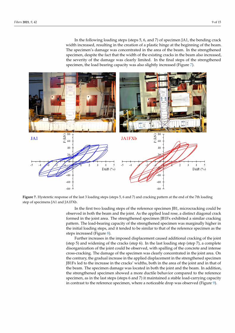
In the following loading steps (steps 5, 6, and 7) of specimen JA1, the bending crackwidth increased, resulting in the creation of a plastic hinge at the beginning of the beam.The specimen’s damage was concentrated in the area of the beam. In the strengthenedspecimen, despite the fact that the width of the existing cracks in the beam also increased,the severity of the damage was clearly limited. In the final steps of the strengthenedspecimen, the load bearing capacity was also slightly increased (Figure 7).
Fibers 2021, 9, x FOR PEER REVIEW 10 of 16
Figure 7. Hysteretic response of the last 3 loading steps (steps 5, 6 and 7) and cracking pattern at the end of the 7th load-ing step of specimens JA1 and JA1FXb.
In the first two loading steps of the reference specimen JB1, microcracking could be observed in both the beam and the joint. As the applied load rose, a distinct diagonal crack formed in the joint area. The strengthened specimen JB1Fx exhibited a similar cracking pattern. The load-bearing capacity of the strengthened specimen was margin-ally higher in the initial loading steps, and it tended to be similar to that of the reference specimen as the steps increased (Figure 8).
Figure 7. Hysteretic response of the last 3 loading steps (steps 5, 6 and 7) and cracking pattern at the end of the 7th loadingstep of specimens JA1 and JA1FXb.
In the first two loading steps of the reference specimen JB1, microcracking could beobserved in both the beam and the joint. As the applied load rose, a distinct diagonal crackformed in the joint area. The strengthened specimen JB1Fx exhibited a similar crackingpattern. The load-bearing capacity of the strengthened specimen was marginally higher inthe initial loading steps, and it tended to be similar to that of the reference specimen as thesteps increased (Figure 8).
Further increases in the imposed displacement caused additional cracking of the joint(step 5) and widening of the cracks (step 6). In the last loading step (step 7), a completedisorganization of the joint could be observed, with spalling of the concrete and intensecross-cracking. The damage of the specimen was clearly concentrated in the joint area. Onthe contrary, the gradual increase in the applied displacement in the strengthened specimenJB1Fx led to the increase in the cracks’ widths, both in the area of the joint and in that ofthe beam. The specimen damage was located in both the joint and the beam. In addition,the strengthened specimen showed a more ductile behavior compared to the referencespecimen, as in the last steps (steps 6 and 7) it maintained a stable load-carrying capacityin contrast to the reference specimen, where a noticeable drop was observed (Figure 9).

Fibers 2021, 9, 42 10 of 15Fibers 2021, 9, x FOR PEER REVIEW 11 of 16
Figure 8. Hysteretic response of the first 4 loading steps (steps 1, 2, 3 and 4) and cracking pattern at the end of the 4th loading step of specimens JB1 and JB1FX.
Further increases in the imposed displacement caused additional cracking of the joint (step 5) and widening of the cracks (step 6). In the last loading step (step 7), a com-plete disorganization of the joint could be observed, with spalling of the concrete and intense cross-cracking. The damage of the specimen was clearly concentrated in the joint area. On the contrary, the gradual increase in the applied displacement in the strength-ened specimen JB1Fx led to the increase in the cracks’ widths, both in the area of the joint and in that of the beam. The specimen damage was located in both the joint and the beam. In addition, the strengthened specimen showed a more ductile behavior compared to the reference specimen, as in the last steps (steps 6 and 7) it maintained a stable load-carrying capacity in contrast to the reference specimen, where a noticeable drop was observed (Figure 9).
Figure 8. Hysteretic response of the first 4 loading steps (steps 1, 2, 3 and 4) and cracking pattern at the end of the 4thloading step of specimens JB1 and JB1FX.
Fibers 2021, 9, x FOR PEER REVIEW 12 of 16
Figure 9. Hysteretic response of the last 3 loading steps (steps 5, 6 and 7) and cracking pattern at the end of the 7th load-ing step of specimens JB1 and JB1FX.
Figure 10 displays the curves of the maximum applied load (P) ratios calculated by the experimentally measured load capacity of the retrofitted specimens per each loading step/drift to the corresponding load of the reference specimens. The values of these ratios indicate the efficiency of the proposed strengthening technique with CFRP ropes, so that further conclusions can be drawn. More specifically, ratio A0 (P+/−) curves refer to the ratios of the maximum imposed load values per drift of the retrofitted specimen JA0Fxb to the corresponding load values of the reference specimen JA0. In the same manner, ra-tio A1 (P+/−) curves represent the load ratios of the retrofitted specimen JA1Fxb to the reference specimen JA1, and ratio B1 P(+/−) curves represent the load ratios of the retro-fitted specimen JB1Fxb to the reference specimen JB1. These ratios for both positive (P+) and negative (P−) imposed load values are, in all examined cases, higher than 1. As such, the experimental results demonstrated in the diagrams of Figure 10 clearly reveal the ability of the applied CFRP ropes to enhance the load-bearing capacity of the tested joint subassemblages.
Figure 10. Comparison of the maximum applied load ratio per each loading step of the tested joints.
Figure 9. Hysteretic response of the last 3 loading steps (steps 5, 6 and 7) and cracking pattern at the end of the 7th loadingstep of specimens JB1 and JB1FX.
Fibers 2021, 9, 42 11 of 15
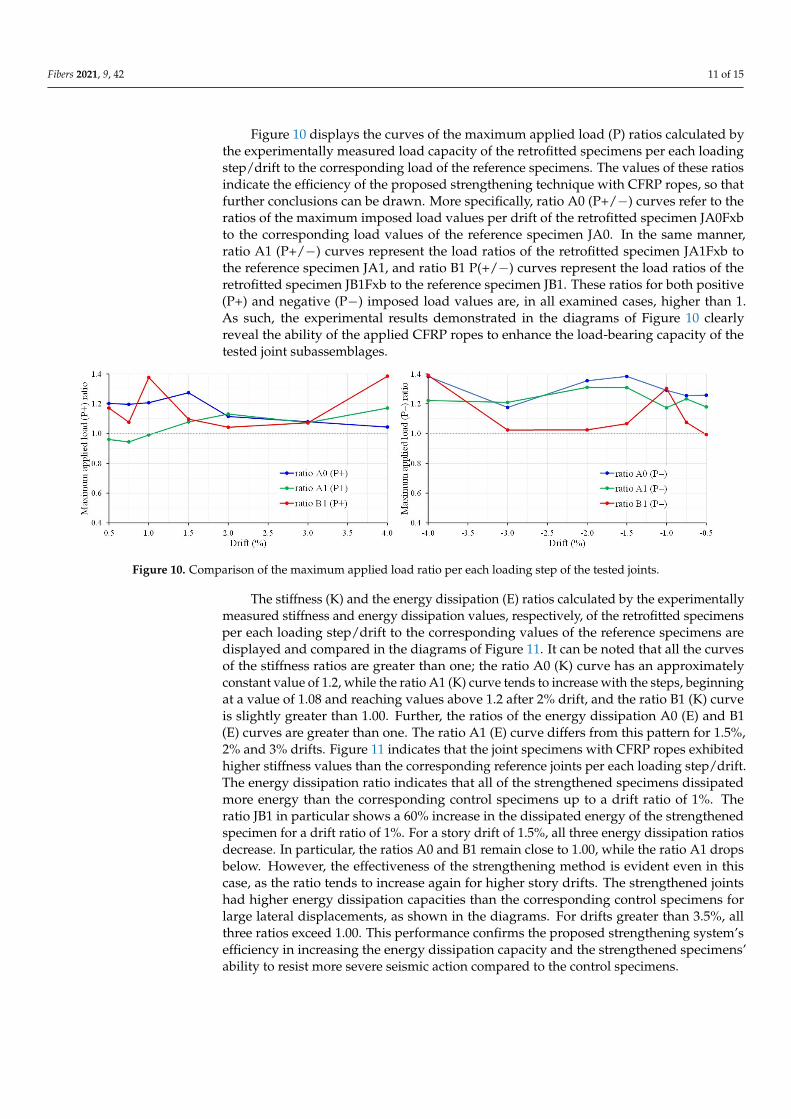
Figure 10 displays the curves of the maximum applied load (P) ratios calculated bythe experimentally measured load capacity of the retrofitted specimens per each loadingstep/drift to the corresponding load of the reference specimens. The values of these ratiosindicate the efficiency of the proposed strengthening technique with CFRP ropes, so thatfurther conclusions can be drawn. More specifically, ratio A0 (P+/−) curves refer to theratios of the maximum imposed load values per drift of the retrofitted specimen JA0Fxbto the corresponding load values of the reference specimen JA0. In the same manner,ratio A1 (P+/−) curves represent the load ratios of the retrofitted specimen JA1Fxb tothe reference specimen JA1, and ratio B1 P(+/−) curves represent the load ratios of theretrofitted specimen JB1Fxb to the reference specimen JB1. These ratios for both positive(P+) and negative (P−) imposed load values are, in all examined cases, higher than 1.As such, the experimental results demonstrated in the diagrams of Figure 10 clearlyreveal the ability of the applied CFRP ropes to enhance the load-bearing capacity of thetested joint subassemblages.
Fibers 2021, 9, x FOR PEER REVIEW 12 of 16
Figure 9. Hysteretic response of the last 3 loading steps (steps 5, 6 and 7) and cracking pattern at the end of the 7th load-ing step of specimens JB1 and JB1FX.
Figure 10 displays the curves of the maximum applied load (P) ratios calculated by the experimentally measured load capacity of the retrofitted specimens per each loading step/drift to the corresponding load of the reference specimens. The values of these ratios indicate the efficiency of the proposed strengthening technique with CFRP ropes, so that further conclusions can be drawn. More specifically, ratio A0 (P+/−) curves refer to the ratios of the maximum imposed load values per drift of the retrofitted specimen JA0Fxb to the corresponding load values of the reference specimen JA0. In the same manner, ra-tio A1 (P+/−) curves represent the load ratios of the retrofitted specimen JA1Fxb to the reference specimen JA1, and ratio B1 P(+/−) curves represent the load ratios of the retro-fitted specimen JB1Fxb to the reference specimen JB1. These ratios for both positive (P+) and negative (P−) imposed load values are, in all examined cases, higher than 1. As such, the experimental results demonstrated in the diagrams of Figure 10 clearly reveal the ability of the applied CFRP ropes to enhance the load-bearing capacity of the tested joint subassemblages.
Figure 10. Comparison of the maximum applied load ratio per each loading step of the tested joints. Figure 10. Comparison of the maximum applied load ratio per each loading step of the tested joints.
The stiffness (K) and the energy dissipation (E) ratios calculated by the experimentallymeasured stiffness and energy dissipation values, respectively, of the retrofitted specimensper each loading step/drift to the corresponding values of the reference specimens aredisplayed and compared in the diagrams of Figure 11. It can be noted that all the curvesof the stiffness ratios are greater than one; the ratio A0 (K) curve has an approximatelyconstant value of 1.2, while the ratio A1 (K) curve tends to increase with the steps, beginningat a value of 1.08 and reaching values above 1.2 after 2% drift, and the ratio B1 (K) curveis slightly greater than 1.00. Further, the ratios of the energy dissipation A0 (E) and B1(E) curves are greater than one. The ratio A1 (E) curve differs from this pattern for 1.5%,2% and 3% drifts. Figure 11 indicates that the joint specimens with CFRP ropes exhibitedhigher stiffness values than the corresponding reference joints per each loading step/drift.The energy dissipation ratio indicates that all of the strengthened specimens dissipatedmore energy than the corresponding control specimens up to a drift ratio of 1%. Theratio JB1 in particular shows a 60% increase in the dissipated energy of the strengthenedspecimen for a drift ratio of 1%. For a story drift of 1.5%, all three energy dissipation ratiosdecrease. In particular, the ratios A0 and B1 remain close to 1.00, while the ratio A1 dropsbelow. However, the effectiveness of the strengthening method is evident even in thiscase, as the ratio tends to increase again for higher story drifts. The strengthened jointshad higher energy dissipation capacities than the corresponding control specimens forlarge lateral displacements, as shown in the diagrams. For drifts greater than 3.5%, allthree ratios exceed 1.00. This performance confirms the proposed strengthening system’sefficiency in increasing the energy dissipation capacity and the strengthened specimens’ability to resist more severe seismic action compared to the control specimens.

Fibers 2021, 9, 42 12 of 15
Fibers 2021, 9, x FOR PEER REVIEW 13 of 16
The stiffness (K) and the energy dissipation (E) ratios calculated by the experimen-tally measured stiffness and energy dissipation values, respectively, of the retrofitted specimens per each loading step/drift to the corresponding values of the reference specimens are displayed and compared in the diagrams of Figure 11. It can be noted that all the curves of the stiffness ratios are greater than one; the ratio A0 (K) curve has an approximately constant value of 1.2, while the ratio A1 (K) curve tends to increase with the steps, beginning at a value of 1.08 and reaching values above 1.2 after 2% drift, and the ratio B1 (K) curve is slightly greater than 1.00. Further, the ratios of the energy dissi-pation A0 (E) and B1 (E) curves are greater than one. The ratio A1 (E) curve differs from this pattern for 1.5%, 2% and 3% drifts. Figure 11 indicates that the joint specimens with CFRP ropes exhibited higher stiffness values than the corresponding reference joints per each loading step/drift. The energy dissipation ratio indicates that all of the strengthened specimens dissipated more energy than the corresponding control specimens up to a drift ratio of 1%. The ratio JB1 in particular shows a 60% increase in the dissipated energy of the strengthened specimen for a drift ratio of 1%. For a story drift of 1.5%, all three energy dissipation ratios decrease. In particular, the ratios A0 and B1 remain close to 1.00, while the ratio A1 drops below. However, the effectiveness of the strengthening method is ev-ident even in this case, as the ratio tends to increase again for higher story drifts. The strengthened joints had higher energy dissipation capacities than the corresponding control specimens for large lateral displacements, as shown in the diagrams. For drifts greater than 3.5%, all three ratios exceed 1.00. This performance confirms the proposed strengthening system’s efficiency in increasing the energy dissipation capacity and the strengthened specimens’ ability to resist more severe seismic action compared to the control specimens
Figure 11. Comparison of the stiffness and energy dissipation ratios per each loading step of the tested joints.
4. Conclusions In this study, experimental tests were carried out to investigate the effectiveness of
CFRP ropes as a strengthening method in deficient RC joints subjected to seismic loads. The experimental program consisted of six exterior full-size beam–column joints. Three of the six tested specimens were reference specimens and three of them were strength-ened with carbon CFRP ropes installed as near-surface-mounted reinforcement against shear. All joint specimens were subjected to the same reverse loading history scheme, with constantly increased imposed displacements per loading step/drift. Three full loading cycles were included in each loading step. The following conclusions can be drawn based on the findings of this experimentally study: • Specimens with CFRP ropes demonstrated a noticeably improved hysteretic per-
formance in terms of both strength and seismic characteristics. The cracking patterns of the strengthened specimens indicate an improved behavior, as the number of cracks was smaller and also the cracks were reduced in width compared to the ref-erence specimens. It should be stressed that, although the reference joint specimen
Figure 11. Comparison of the stiffness and energy dissipation ratios per each loading step of the tested joints.
4. Conclusions
In this study, experimental tests were carried out to investigate the effectiveness ofCFRP ropes as a strengthening method in deficient RC joints subjected to seismic loads.The experimental program consisted of six exterior full-size beam–column joints. Three ofthe six tested specimens were reference specimens and three of them were strengthenedwith carbon CFRP ropes installed as near-surface-mounted reinforcement against shear. Alljoint specimens were subjected to the same reverse loading history scheme, with constantlyincreased imposed displacements per loading step/drift. Three full loading cycles wereincluded in each loading step. The following conclusions can be drawn based on thefindings of this experimentally study:
• Specimens with CFRP ropes demonstrated a noticeably improved hysteretic perfor-mance in terms of both strength and seismic characteristics. The cracking patterns ofthe strengthened specimens indicate an improved behavior, as the number of crackswas smaller and also the cracks were reduced in width compared to the referencespecimens. It should be stressed that, although the reference joint specimen presentedsevere damages/cracks in the joint area, cracking of the strengthened specimen wasnot observed in the joint, but only appeared in the beam area;
• The hysteretic curves of the strengthened specimens indicate an enhanced cyclicresponse with respect to the response of the corresponding reference specimens. Itis noted that in the last loading cycles, the strengthened specimens demonstrateda stabilized behavior with constant load-bearing capacity, whereas the referencespecimens exhibited a reduced one;
• The maximum applied load and stiffness ratios in all the examined cases are greaterthan 1.00, indicating that the load capacity in positive and negative loading directionsand stiffness values were increased in the specimens with CFRP ropes in comparisonto the reference ones;
• The load, stiffness and energy dissipation values at higher loading steps/drifts ofthe strengthened joint specimens were greater than the corresponding values of thereference specimens, implying that the application of CFRP ropes to strengthen thebeam–column joints was an effective method of increasing load, stiffness and energydissipation capacity, and of improving the overall hysteretic response;
• The proposed technique is easy and fast to apply. It requires minimal intervention inthe strengthening area, and it is not restricted by the presence of surrounding beams.However, when the NSM method is selected for the application of the CFRP rope, thearea under strengthening must have a sufficient reinforcement cover;
• The effectiveness of CFRP ropes as a rehabilitated method of deficient RC beam–column joints was demonstrated in the experiments presented herein. However, moreresearch is required to accurately evaluate the advantages of the implemented strength-ening method and, ultimately, to develop design models for professorial designers.More research is needed on FRP rope application techniques, such as the embedded

Fibers 2021, 9, 42 13 of 15
through the joint section (ETS method) rope installation method. The investigationof additional reinforcement configurations, such as the combined strengthening ofcolumns and joints, would be of particular interest. For example, in beam–columnjoints where the damage is recorded at the beginning of the column, the strengtheningmethod could be used to investigate the possibility of transferring the damage to thebeam (within the framework of strong column/weak beam design).
Author Contributions: Conceptualization, C.G.K.; methodology, E.G.; validation, A.G.Z. and C.E.C.;formal analysis, E.G., A.G.Z. and V.K.K.; investigation, E.G., M.O., M.K. and D.S.; data curation, E.G.,A.G.Z. and V.K.K.; writing—original draft preparation, E.G. and A.G.Z.; writing—review and editing,V.K.K. and C.E.C.; visualization, A.G.Z. and C.E.C.; supervision, C.G.K. All authors have read andagreed to the published version of the manuscript.
Funding: This research received no external funding.
Institutional Review Board Statement: Not applicable.
Informed Consent Statement: Not applicable.
Data Availability Statement: Data available on request.
Acknowledgments: Author Adamantis G. Zapris gratefully acknowledges the financial supportreceived from Eugenides Foundation towards doctoral studies.
Conflicts of Interest: The authors declare no conflict of interest.
References1. Vecchi, F.; Belletti, B. Capacity Assessment of Existing RC Columns. Buildings 2021, 11, 161. [CrossRef]2. Belletti, B.; Stocchi, A.; Scolari, M.; Vecchi, F. Validation of the PARC_CL 2.0 Crack Model for the Assessment of the Nonlinear
Behaviour of RC Structures Subjected to Seismic Action: SMART 2013 Shaking Table Test Simulation. Eng. Struct. 2017,150, 759–773. [CrossRef]
3. Kalogeropoulos, G.I.; Tsonos, A.-D.G. Improvement of the Cyclic Response of RC Columns with Inadequate Lap Splices-Experimental and Analytical Investigation. Earthq. Struct. 2019, 16, 279–293. [CrossRef]
4. Mostofinejad, D.; Akhlaghi, A. Experimental Investigation of the Efficacy of EBROG Method in Seismic Rehabilitation of DeficientReinforced Concrete Beam–Column Joints Using CFRP Sheets. J. Compos. Constr. 2017, 21, 04016116. [CrossRef]
5. Tsonos, A.G. Lateral Load Response of Strengthened Reinforced Concrete Beam-to-Column Joints. Aci Struct. J. 1999, 96, 46–56.6. Tsonos, A. Seismic Retrofit of R/C Beam-to-Column Joints Using Local Three-Sided Jackets. Eur. Earthq. Eng. 2001, 15, 48–64.7. Kalogeropoulos, G.I.; Tsonos, A.-D.G.; Konstantinidis, D.; Iakovidis, P.E. Earthquake-Resistant Rehabilitation of Existing RC
Structures Using High-Strength Steel Fiber-Reinforced Concrete Jackets. Earthq. Struct. 2019, 17, 115–129. [CrossRef]8. Karayannis, C.G.; Chalioris, C.E.; Sirkelis, G.M. Local Retrofit of Exterior RC Beam–Column Joints Using Thin RC Jackets—An
Experimental Study. Earthq. Eng. Struct. Dyn. 2008, 37, 727–746. [CrossRef]9. Pohoryles, D.A.; Melo, J.; Rossetto, T.; Varum, H.; Bisby, L. Seismic Retrofit Schemes with FRP for Deficient RC Beam-Column
Joints: State-of-the-Art Review. J. Compos. Constr. 2019, 23, 03119001. [CrossRef]10. Al-Salloum, Y.A.; Siddiqui, N.A.; Elsanadedy, H.M.; Abadel, A.A.; Aqel, M.A. Textile-Reinforced Mortar versus FRP as Strength-
ening Material for Seismically Deficient RC Beam-Column Joints. J. Compos. Constr. 2011, 15, 920–933. [CrossRef]11. Hadi, M.N.S.; Tran, T.M. Seismic Rehabilitation of Reinforced Concrete Beam–Column Joints by Bonding with Concrete Covers
and Wrapping with FRP Composites. Mater. Struct. 2016, 49, 467–485. [CrossRef]12. Santis, S.D.; de Felice, G.; Roscini, F. Retrofitting of Masonry Vaults by Basalt Textile-Reinforced Mortar Overlays. Int. J. Archit.
Herit. 2019, 13, 1061–1077. [CrossRef]13. Roscini, F.; De Santis, S.; De Felice, G. Experimental Investigation on the Mechanical Behaviour of Mortar-Based Strengthening
Systems. Struct. Anal. Hist. Constr. Anamn. Diagn. Ther. Control. 2016, 384–390.14. Spadea, G.; Bencardino, F.; Swamy, R.N. Structural Behavior of Composite RC Beams with Externally Bonded CFRP. J. Compos.
Constr. 1998, 2, 132–137. [CrossRef]15. Spadea, G.; Bencardino, F.; Swamy, R.N. Optimizing the Performance Characteristics of Beams Strengthened with Bonded CFRP
Laminates. Mater. Struct. 2000, 33, 119–126. [CrossRef]16. Tomlinson, D.; Fam, A. Performance of Concrete Beams Reinforced with Basalt FRP for Flexure and Shear. J. Compos. Constr. 2015,
19, 04014036. [CrossRef]17. Mohammed, A.A.; Manalo, A.C.; Ferdous, W.; Zhuge, Y.; Vijay, P.V.; Alkinani, A.Q.; Fam, A. State-of-the-Art of Prefabricated FRP
Composite Jackets for Structural Repair. Eng. Sci. Technol. Int. J. 2020, 23, 1244–1258. [CrossRef]18. Mohammed, A.A.; Manalo, A.C.; Ferdous, W.; Zhuge, Y.; Vijay, P.V.; Pettigrew, J. Experimental and Numerical Evaluations on the
Behaviour of Structures Repaired Using Prefabricated FRP Composites Jacket. Eng. Struct. 2020, 210, 110358. [CrossRef]

Fibers 2021, 9, 42 14 of 15
19. Siddika, A.; Mamun, M.A.A.; Ferdous, W.; Alyousef, R. Performances, Challenges and Opportunities in Strengthening ReinforcedConcrete Structures by Using FRPs—A State-of-the-Art Review. Eng. Fail. Anal. 2020, 111, 104480. [CrossRef]
20. Mohammed, A.A.; Manalo, A.; Ferdous, W.; Abousnina, R.; AlAjarmeh, O.; Vijay, P.V.; Benmokrane, B. Design Considerationsfor Prefabricated Composite Jackets for Structural Repair: Parametric Investigation and Case Study. Compos. Struct. 2021,261, 113288. [CrossRef]
21. Tsonos, A.G. An Innovative Solution for Strengthening of Old R/C Structures and for Improving the FRP Strengthening Method.Struct. Monit. Maint. 2014, 1, 323–338. [CrossRef]
22. Spadea, G.; Swamy, R.N.; Bencardino, F. Strength and Ductility of RC Beams Repaired with Bonded CFRP Laminates. J. BridgeEng. 2001, 6, 349–355. [CrossRef]
23. Bencardino, F.; Spadea, G.; Swamy, R.N. Strength and Ductility of Reinforced Concrete Beams Externally Reinforced with CarbonFiber Fabric. Struct. J. 2002, 99, 163–171. [CrossRef]
24. Ferdous, W. Effect of beam-column joint stiffness on the design of beams. In Proceedings of the 23rd Australasian Conference onthe Mechanics of Structures and Materials (ACMSM23), Byron Bay, Australia, 9–12 December 2014.
25. Spadea, G.; Bencardino, F.; Sorrenti, F.; Swamy, R.N. Structural Effectiveness of FRP Materials in Strengthening RC Beams. Eng.Struct. 2015, 99, 631–641. [CrossRef]
26. McSwiggan, C.; Fam, A. Bio-Based Resins for Flexural Strengthening of Reinforced Concrete Beams with FRP Sheets. Constr.Build. Mater. 2017, 131, 618–629. [CrossRef]
27. Bencardino, F.; Spadea, G.; Swamy, R.N. The Problem of Shear in RC Beams Strengthened with CFRP Laminates. Constr. Build.Mater. 2007, 21, 1997–2006. [CrossRef]
28. Chalioris, C.E.; Zapris, A.G.; Karayannis, C.G. U-Jacketing Applications of Fiber-Reinforced Polymers in Reinforced ConcreteT-Beams against Shear—Tests and Design. Fibers 2020, 8, 13. [CrossRef]
29. Mandal, S.; Hoskin, A.; Fam, A. Influence of Concrete Strength on Confinement Effectiveness of Fiber-Reinforced PolymerCircular Jackets. Aci Struct. J. 2005, 102, 383. [CrossRef]
30. Green, M.F.; Bisby, L.A.; Fam, A.Z.; Kodur, V.K.R. FRP Confined Concrete Columns: Behaviour under Extreme Conditions. Cem.Concr. Compos. 2006, 28, 928–937. [CrossRef]
31. Anagnostou, E.; Rousakis, T.C.; Karabinis, A.I. Seismic Retrofitting of Damaged RC Columns with Lap-Spliced Bars Using FRPSheets. Compos. Part B Eng. 2019, 166, 598–612. [CrossRef]
32. Tsonos, A.-D.G.; Kalogeropoulos, G.I.; Iakovidis, P.E.; Konstantinidis, D. Seismic Retrofitting of Pre-1970 RC Bridge ColumnsUsing Innovative Jackets. Int. J. Struct. Eng. 2017, 8, 133–147. [CrossRef]
33. Karayannis, C.G.; Sirkelis, G.M. Strengthening and Rehabilitation of RC Beam–Column Joints Using Carbon-FRP Jacketing andEpoxy Resin Injection. Earthq. Eng. Struct. Dyn. 2008, 37, 769–790. [CrossRef]
34. Sezen, H. Repair and Strengthening of Reinforced Concrete Beam-Column Joints with Fiber-Reinforced Polymer Composites. J.Compos. Constr. 2012, 16, 499–506. [CrossRef]
35. Kalogeropoulos, G.I.; Tsonos, A.-D.G.; Konstandinidis, D.; Tsetines, S. Pre-Earthquake and Post-Earthquake Retrofitting of PoorlyDetailed Exterior RC Beam-to-Column Joints. Eng. Struct. 2016, 109, 1–15. [CrossRef]
36. Karayannis, C.G.; Golias, E. Full Scale Tests of RC Joints with Minor to Moderate Seismic Damage Repaired Using C-FRP Sheets.Earthq. Struct. 2018, 15, 617–627. [CrossRef]
37. Li, B.; Chua, H.Y. Grace Seismic Performance of Strengthened Reinforced Concrete Beam-Column Joints Using FRP Composites.J. Struct. Eng. 2009, 135, 1177–1190. [CrossRef]
38. Bing, L.; Qian, K. Seismic Behavior of Reinforced Concrete Interior Beam-Wide Column Joints Repaired Using FRP. J. Compos.Constr. 2011, 15, 327–338. [CrossRef]
39. Tsonos, A.G. Effectiveness of CFRP-Jackets and RC-Jackets in Post-Earthquake and Pre-Earthquake Retrofitting of Beam–ColumnSubassemblages. Eng. Struct. 2008, 30, 777–793. [CrossRef]
40. Karayannis, C.G.; Golias, E. Strengthening of Deficient RC Joints with Diagonally Placed External C-FRP Ropes. Earthq. Struct.2021, 20, 123–132. [CrossRef]
41. Chalioris, C.E.; Kosmidou, P.-M.K.; Papadopoulos, N.A. Investigation of a New Strengthening Technique for RC Deep BeamsUsing Carbon FRP Ropes as Transverse Reinforcements. Fibers 2018, 6, 52. [CrossRef]
42. Ghorbani, M.; Mostofinejad, D.; Hosseini, A. Bond Behavior of CFRP Sheets Attached to Concrete through EBR and EBROGJoints Subject to Mixed-Mode I/II Loading. J. Compos. Constr. 2017, 21, 04017034. [CrossRef]
43. Mostofinejad, D.; Akhlaghi, A. Flexural Strengthening of Reinforced Concrete Beam-Column Joints Using an InnovativeAnchorage System. Aci Struct. J. 2017, 114. [CrossRef]
44. Mostofinejad, D.; Hajrasouliha, M. 3D Beam–Column Corner Joints Retrofitted with X-Shaped FRP Sheets Attached via theEBROG Technique. Eng. Struct. 2019, 183, 987–998. [CrossRef]
45. Akhlaghi, A.; Mostofinejad, D. Experimental and Analytical Assessment of Different Anchorage Systems Used for CFRPFlexurally Retrofitted Exterior RC Beam-Column Connections. Structures 2020, 28, 881–893. [CrossRef]
46. Kaya, E.; Kütan, C.; Sheikh, S.; Ilki, A. Flexural Retrofit of Support Regions of Reinforced Concrete Beams with Anchored FRPRopes Using NSM and ETS Methods under Reversed Cyclic Loading. J. Compos. Constr. 2017, 21, 04016072. [CrossRef]
47. Bourget, S.; El-Saikaly, G.; Chaallal, O. Behavior of Reinforced Concrete T-Beams Strengthened in Shear Using Closed CarbonFiber-Reinforced Polymer Stirrups Made of Laminates and Ropes. Aci Struct. J. 2017, 114. [CrossRef]

Fibers 2021, 9, 42 15 of 15
48. Chalioris, C.; Papadopoulos, N.; Panagiotopoulos, T.; Kosmidou, P. Shear Strengthening of Reinforced Concrete Deep Beamswithout Stirrups Using Carbon Fibre Rope as Transverse Link Reinforcement. In Proceedings of the 12th Annual InternationalConference on Composites/Nano Engineering ICCE-25, Rome, Italy, 16–22 July 2017; pp. 16–22.
49. Al-Bayati, G. Torsional Strengthening of RC Beams Using NSM CFRP Rope and Innovative Adhesives. Compos. Struct. 2018,13, 190–202. [CrossRef]
50. Rousakis, T.C.; Tourtouras, I.S. RC Columns of Square Section—Passive and Active Confinement with Composite Ropes. Compos.Part B Eng. 2014, 58, 573–581. [CrossRef]
51. Abdollahnia, H.; Alizadeh Elizei, M.H.; Reza Kashyzadeh, K. Fatigue Life Assessment of Integral Concrete Bridges with HCross-Section Steel Piles Mounted in Water. J Fail. Anal. Prev. 2020, 20, 1661–1672. [CrossRef]
52. Abdollahnia, H.; Alizadeh Elizei, M.H.; Reza Kashyzadeh, K. Low-Cycle Fatigue Behavior of H-Shaped Steel Piles of an IntegralConcrete Bridge Subjected to Temperature Variations. Mater. Today Proc. 2020. [CrossRef]
53. Golias, E.; Lindenthal, H.; Schlüter, F.-H.; Karabinis, A.I. Ertüchtigung Seismisch Beschädigter Rahmenknoten Aus StahlbetonMittels FRP-Filamentbündelverbindungen. Bautechnik 2020, 97, 268–278. [CrossRef]


![CFRP [Wet-preg]](https://static.fdocuments.us/doc/165x107/546e6828b4af9faa268b4674/cfrp-wet-preg.jpg)