APPLICATION OF TIME DELAY VALVES - IDC-Online · APPLICATION OF TIME DELAY VALVES Figure 6.8 Time...
8
APPLICATION OF TIME DELAY VALVES Figure 6.8 Time Delay Valve Circuit [N.C]
Transcript of APPLICATION OF TIME DELAY VALVES - IDC-Online · APPLICATION OF TIME DELAY VALVES Figure 6.8 Time...

APPLICATION OF TIME DELAY VALVES
Figure 6.8 Time Delay Valve Circuit [N.C]

Ex.: 1 Use of Pressure Sequence Valve in Clamping Application
Work Pieces are to be clamped using a Pneumatic Cylinder. It is necessary that thepiston advances on actuation of a Hand Push button only after the desired pressure isavailable in the working pressure supply. The piston should retract on releasing thesame push button
F=0
4 2
1
14 12
5 3
2
12 1
3
2
1
S1
3
2
1 3
1 12
S1
Figure 6.9 Use of Pressure Sequence Valve in Clamping Application
Exercise 2: Stamping of Badges
Badges are to be produced from a very thin metal sheetA press with stamping die is available for this purpose . The double acting cylindershould extend when both push buttons S1 and S2 are pressed simultaneously.The return stroke to occur automatically only after preset pressure has beenreached in the cylinder at the forward end position[to get the consistent quality]The cylinder should retract even if an Emergency push button S3 is pressed.

Figure 6.10 Stamping of Badges
Example 3: Clamping Device
Figure 6.9 Figure 6.9
Figure 6.11 Clamping Device

A push button is to control the forward stroke. After the piton rod has reached theforward end position, the components are to be pressed together for 20 seconds. Thenthe piston rod should return to initial position automatically.The return stroke must occur even if the start push button is still depressed.A new start signal may only become effective after the initial position has beenreached and after the push button has been released
Example 3: Clamping Device - Circuit
Figure 6.12 Clamping Devices – Circuit
F=0
4 2
1
14 12
5 3
95%
2
1
10
3 50%
2
1
12
3
S1 S2
2
1
S2
3
2
1
S1
3
2
1 3
N.O Timer [ 2 sec} N.C. Timer [ 10 sec]

Ex. 4: Two Hand Safety Block
A Pneumatic Cylinder has to advance on actuation of two push buttonssimultaneously [both the hands of the operator are engaged]. The second push buttonis activated within short interval of time after actuation of first button./If any one of the push button is released, the piston of cylinder should Retract.
Figure 6.13 Two Hand Safety Block
Exercise 2: Stamping Device
Articles are to be stamped using a stamping deviceBy pressing two push buttons simultaneously, the movable stamping die is pusheddown and the article is stamped .After desired pressure is reached the die returns to its initial position even though the
push buttons are still pressedNext cycle should be possible only after the push buttons are released
F=0
10%
2
1
10
3
1 12
1 12
2
1
10
3
2
1 3
2
1 3
4 2
1
14 12
5 3N.O.TIMER [2 Sec]
NOT GATE
P.B.2P.B. 1

Figure 6.14 Stamping Device
Exercise 2: Bonding Application
Figure 6.15 Bonding Application

Plastic Cylinders are to be bonded using a Pneumatic cylinder.It is required that piston performs forward stroke on actuation of a hand push buttonReturn motion should take place after the piston reaches forward end positioncylinder attains full pressure of 6 bar and remains in that position for 10 secIt should be possible to restart the forward motion only 20 sec after the pistonreaches home position.
Development of Pneumatic Circuit
Figure 6.16 Development of Pneumatic Circuit
F=0
4 2
1
14 12
5 3
CONDITION 2 CONDITION 5
CONDITION 1
CONDITION 3
CONDITION 4
CONDITION 6
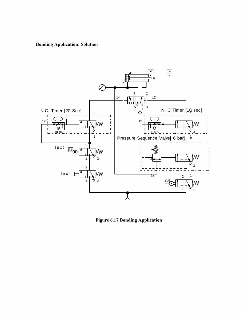
Bonding Application: Solution
Figure 6.17 Bonding Application
F=0
4 2
1
14 12
5 3
2
12 1
3
100%
2
1
12
3100%
2
1
12
3
2
1
S1
3
2
1
S2
3
2
1 3
S1 S2
Te x t
N. C Timer [10 sec]
Pressure Sequence Valve[ 6 bar]
N.C. Timer [20 Sec]
Te x t
Parithy
Typewritten Text
Source : http://elearningatria.files.wordpress.com/2013/10/hydraulics-and-pneumatics.pdf


![[ 3000 Series Time Delay Relays and Measuring Relays ... · [ 3000 Series Time Delay Relays and Measuring Relays ] ... Measuring Relays ] • Time Delay Relays ... Dear Reader, Dear](https://static.fdocuments.us/doc/165x107/5b85683b7f8b9aec488e43dd/-3000-series-time-delay-relays-and-measuring-relays-3000-series-time.jpg)
