Application of Solar Powered Electronic Notice Board to ...
6
1 GJT Vol. 4, No. 2, March, 2020 Application of Solar Powered Electronic Notice Board to Blasting Schedules in Mining Operations* 1 E. Normanyo and 1 I. A. Danquah 1 University of Mines and Technology (UMaT), Tarkwa, Ghana Normanyo, E. and Danquah, I. A. (2020), “Application of Solar Powered Electronic Notice Board to Blasting Schedules in Mining Operations”, Ghana Journal of Technology, Vol. 4, No. 2, pp. 1 - 6. Abstract Wireless electronic notice boards offer great advantages and are very significant in diverse areas. In this paper, a solar powered wireless electronic notice board was designed utilising global system for mobile communication technology, Arduino Uno board with ATmega328P microcontroller to display the blasting schedules in mining operations. A prototype of the system was constructed. The ATmega328P microcontroller was programmed using the Arduino Integrated Development Environment software while the system was simulated using the Proteus software before the physical implementation of the system was done. The simulated and the physical implementation results showed that the system is able to display the blasting schedules of the mine. Cost of implementation stood at US$ 864.05. Keywords: Microcontroller, Notice Board, Photovoltaic, Simulation, Wireless 1 Introduction Notice boards are one of the widely used means to convey messages. Nowadays people prefer to communicate while on the move since the invention of mobile phones which employs the use of Global System for Mobile Communication (GSM) technology. Globally over one billion people have recognised the use of GSM for mobile phone applications. With regards to this technology, GSM based electronic notice boards are used as a major way of displaying information in many public places such as the hospitals, railway stations, schools etc. Electronic notice boards can also be employed in the mining industry to simplify the real time noticing of blasting events. Blasting injuries sometimes result from failure to communicate the blasting schedules to the workers, visitors and the public. In some mining companies, markers are used to write the new blasting events on the notice boards. This method is time wasting and costly considering the fuel used by cars to go round and update the notice boards. Furthermore, the information written on the notice boards is sometimes wiped away by rain preventing the information from reaching the targeted public. In some cases, the notice boards are not updated on time which sometimes leads to lack of awareness of the blasting events in particular. Several research works have been reported in the literature regarding development of electronic notice boards using microcontrollers hence, telecommunication technology. Notable amongst them are GSM based electronic display boards using ATmega microcontroller (Bhoyar et al., 2014; Gurav and Jagtap, 2015; Kamboj and Abrol, 2013; Kamdar et al., 2013; Ketkar et al., 2013; Otuoze et al., 2016; Reddy and Venkareshwarlu, 2013; Saini et al., 2014; Sharma et al., 2015; Singh et al., 2015), deploying PIC 16F877A microcontroller (Dogo et al., 2014; Hakani, 2014; San et al., 2013). ARM microprocessor was utilised by Mao (2018) whilst ARM7 microcontroller was used by Kumar et al. (2016). Gaikwad et al. (2013) made use of Zigbee technology whilst Selvakumari et al. (2015) made use of the power consumption reducing Raspberry Pi with JavaScript coding to implement electronic information notice boards. However, Raspberry Pi was combined with Internet of Things (IoT) by Srivastava and Jakkani (2018). Gowrishankar et al. (2018) created an improved Light Emitting Diode (LED) display notice board with GSM technology by transferring the Short Message Service (SMS) through cellular device and provided a dual system for changing messages. The system was both AC and solar powered. The system turns ON or OFF automatically with the aid of a motion detector. Gayathri et al. (2015) introduced the development of wireless notice boards with self-generating power from a built-in solar panel for its working and the main advantage obtained from this work was the major reduction in power consumption and manpower. The messages were able to pass immediately to the display board without delay. Clearly, wireless electronic notice boards offer great advantages. Little work, however, has been done in using them in mining operations. This paper offers a solar powered wireless electronic notice board based on GSM technology to display the blasting schedules for mining operations. Fig. 1 shows a typical blasting notice put on a board in a mine. *Manuscript received September 16, 2016 Revised version accepted February 27, 2020
Transcript of Application of Solar Powered Electronic Notice Board to ...

1 GJT Vol. 4, No. 2, March, 2020
Application of Solar Powered Electronic Notice Board to Blasting
Schedules in Mining Operations*
1E. Normanyo and
1I. A. Danquah
1University of Mines and Technology (UMaT), Tarkwa, Ghana
Normanyo, E. and Danquah, I. A. (2020), “Application of Solar Powered Electronic Notice Board to Blasting
Schedules in Mining Operations”, Ghana Journal of Technology, Vol. 4, No. 2, pp. 1 - 6.
Abstract
Wireless electronic notice boards offer great advantages and are very significant in diverse areas. In this paper, a solar
powered wireless electronic notice board was designed utilising global system for mobile communication technology,
Arduino Uno board with ATmega328P microcontroller to display the blasting schedules in mining operations. A prototype
of the system was constructed. The ATmega328P microcontroller was programmed using the Arduino Integrated
Development Environment software while the system was simulated using the Proteus software before the physical
implementation of the system was done. The simulated and the physical implementation results showed that the system is
able to display the blasting schedules of the mine. Cost of implementation stood at US$ 864.05.
Keywords: Microcontroller, Notice Board, Photovoltaic, Simulation, Wireless
1 Introduction
Notice boards are one of the widely used means to
convey messages. Nowadays people prefer to
communicate while on the move since the
invention of mobile phones which employs the use
of Global System for Mobile Communication
(GSM) technology. Globally over one billion
people have recognised the use of GSM for mobile
phone applications. With regards to this
technology, GSM based electronic notice boards
are used as a major way of displaying information
in many public places such as the hospitals, railway
stations, schools etc. Electronic notice boards can
also be employed in the mining industry to simplify
the real time noticing of blasting events. Blasting
injuries sometimes result from failure to
communicate the blasting schedules to the workers,
visitors and the public.
In some mining companies, markers are used to
write the new blasting events on the notice boards.
This method is time wasting and costly considering
the fuel used by cars to go round and update the
notice boards. Furthermore, the information written
on the notice boards is sometimes wiped away by
rain preventing the information from reaching the
targeted public. In some cases, the notice boards
are not updated on time which sometimes leads to
lack of awareness of the blasting events in
particular.
Several research works have been reported in the
literature regarding development of electronic
notice boards using microcontrollers hence,
telecommunication technology. Notable amongst
them are GSM based electronic display boards
using ATmega microcontroller (Bhoyar et al.,
2014; Gurav and Jagtap, 2015; Kamboj and Abrol,
2013; Kamdar et al., 2013; Ketkar et al., 2013;
Otuoze et al., 2016; Reddy and Venkareshwarlu,
2013; Saini et al., 2014; Sharma et al., 2015; Singh
et al., 2015), deploying PIC 16F877A
microcontroller (Dogo et al., 2014; Hakani, 2014;
San et al., 2013). ARM microprocessor was
utilised by Mao (2018) whilst ARM7
microcontroller was used by Kumar et al. (2016).
Gaikwad et al. (2013) made use of Zigbee
technology whilst Selvakumari et al. (2015) made
use of the power consumption reducing Raspberry
Pi with JavaScript coding to implement electronic
information notice boards. However, Raspberry Pi
was combined with Internet of Things (IoT) by
Srivastava and Jakkani (2018). Gowrishankar et al.
(2018) created an improved Light Emitting Diode
(LED) display notice board with GSM technology
by transferring the Short Message Service (SMS)
through cellular device and provided a dual system
for changing messages. The system was both AC
and solar powered. The system turns ON or OFF
automatically with the aid of a motion detector.
Gayathri et al. (2015) introduced the development
of wireless notice boards with self-generating
power from a built-in solar panel for its working
and the main advantage obtained from this work
was the major reduction in power consumption and
manpower. The messages were able to pass
immediately to the display board without delay.
Clearly, wireless electronic notice boards offer
great advantages. Little work, however, has been
done in using them in mining operations. This
paper offers a solar powered wireless electronic
notice board based on GSM technology to display
the blasting schedules for mining operations. Fig. 1
shows a typical blasting notice put on a board in a
mine.
*Manuscript received September 16, 2016
Revised version accepted February 27, 2020

2 GJT Vol. 4, No. 2, March, 2020
Fig. 1 Metallic Blasting Notice Board at NGR
2 Resources and Methods Used
2.1 Materials
The hardware materials required are the GSM
shield, Arduino Uno with ATmega 328P, 43 bar-
type professional-grade large screen display, solar
panel. The software used for the programming and
simulations are Proteus version 8.1 and Arduino
Integrated Development Environment (IDE),
respectively. Fig. 2 to Fig. 5 depict the hardware
materials utilised.
Fig. 2 The Arduino GSM Shield
USB
Digital Pins
DC
Input
Power pins Analogue
pins
ISSP
Power LED
ATmega328
Microcontroller
Reset
Fig. 3 The Arduino UNO Board
Fig. 4 The 20 × 4 LCD Display
Fig. 5 Solar Panel
2.2 Methods
The methods employed include the design concept,
data collection and analysis, power supply
computations, flowchart of the designed system,
system modelling and simulations, physical
implementation of the designed system and cost
analysis.
2.2.1 Design Concept
In this design, the operator sends the blasting times
in the form of a text message from his mobile
phone to the GSM modem. The GSM modem is
configured using simple AT commands which
allow the GSM modem to interface with the
microcontroller. When the GSM modem receives
the message from the phone, it is then taken to the
programmed microcontroller and then displayed on
the LCD screen. Fig. 6 shows the block diagram of
the design.
Mobile Phone
GSM Modem
(Arduino Uno)
Microcontroller
(Arduino Uno)
LCD Display Screen
(20 × 4 LCD)
Regulated DC
Solar PV Panel
Fig. 6 Block Diagram of the Proposed Design
2.2.2 Data Collection and Analysis
The annual 22 - year average of direct radiation for
most locations in Ghana is taken to be 4.40 (Anon.,
2016). Distances from the mine for locations where
blasting of rock is required could be averaged as 20
km. In any case, messaging using the GSM modem
is not constrained by distances encountered in the
mines.
2.2.3 Power Supply Computations
The power consumption of components is listed in
Table 1.
3 GJT Vol. 4, No. 2, March, 2020
Table 1 Power Consumption of the Components
Device
Rated
Current
(mA)
Operating
Voltage
(V)
Power
Consu-
med
(W)
Energy
Consumed
in 24 Hrs
(WH/day)
ATmega
328 50 5 0.25 6
Arduino
GSM
Shield
450 5 2.25 54
Large
Screen
Display
- - 105 2580
Total 107.5 2640
Total energy required by PV panel is given by
Equation (1), and the size of the solar panel is
given by Equation (2).
L CPV E E E
= 1.3 2640 = 3432 WH/day
where, PVE = total energy required of PV panel,
WH/day; C
E = energy consumed per day, WH/day;
LE = a constant for energy lost in the system.
where, SP = size of the panel, Wp ; PVE = total
energy required of PV panel, WH/day; FP = panel
generation factor.
The battery sized for 1day autonomy is given by
Equation (3).
cEEBC = =
V V
where, BC = battery capacity, AH; E = energy
consumed by the system in a day, WH; V =
nominal battery voltage, V; cE = energy consumed
by the system per day, WH/day
2640 WH
BC12
= 220 AH
For this system, battery is rated at 12 VDC, 220
AH.
For the power supply circuit, a capacitor (C1) of
capacitance 0.1 µF, the 1N4744A zener diode with
a reverse breakdown voltage of 15 V and the 7805
voltage regulator were employed. C1 is to prevent
static discharge that is, the sudden flow of
electricity between two electrically charged objects.
The 1N4744A zener diode prevents the reverse
flow of current which can destroy the solar panel.
The 7805 voltage regulator IC steps down the 12 V
from the battery source to 5 V as required by the
system. The power supply circuit is shown in Fig.
7.
Fig. 7 Power Supply Circuit for the Designed
System
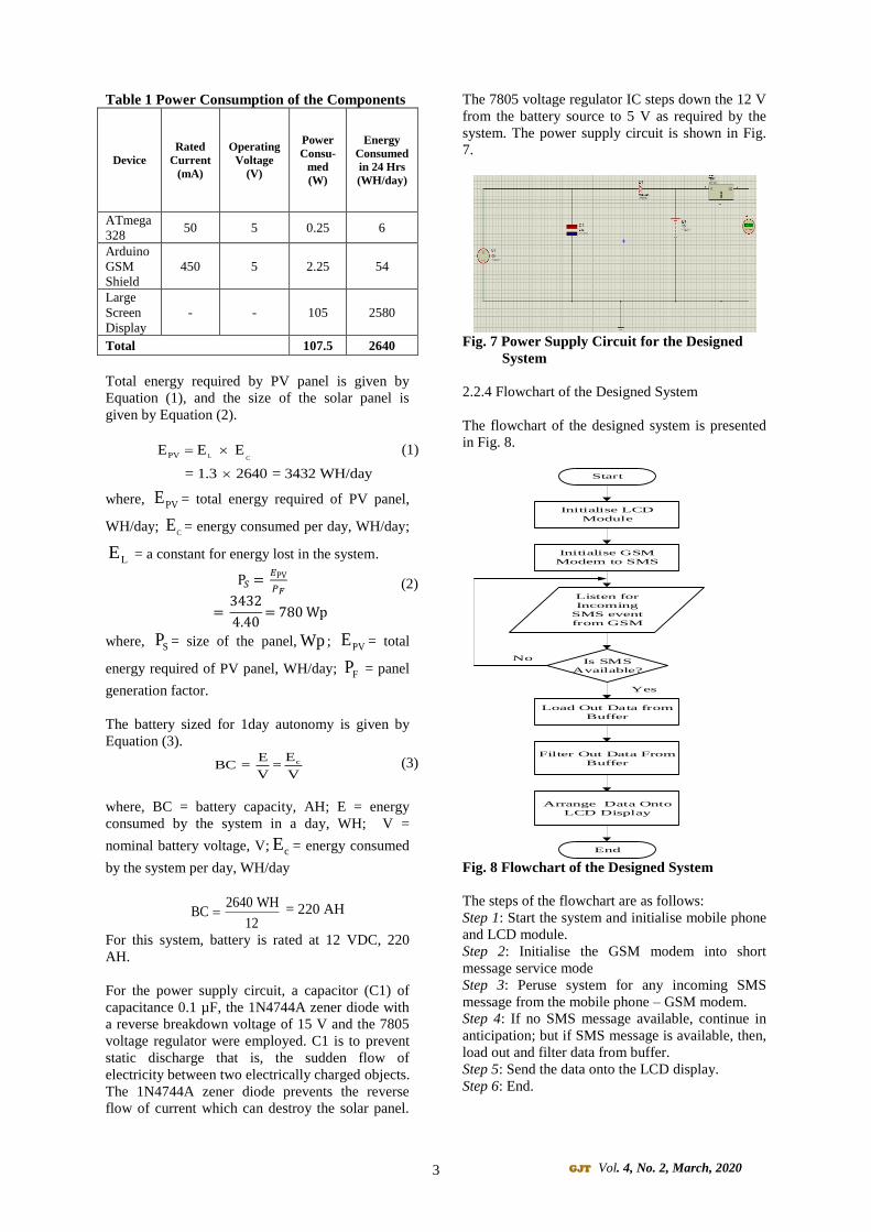
2.2.4 Flowchart of the Designed System
The flowchart of the designed system is presented
in Fig. 8.
Start
Initialise LCD
Module
Initialise GSM
Modem to SMS
Listen for
Incoming
SMS event
from GSM
Is SMS
Available?
Load Out Data from
Buffer
Filter Out Data From
Buffer
Arrange Data Onto
LCD Display
No
Yes
End Fig. 8 Flowchart of the Designed System
The steps of the flowchart are as follows:
Step 1: Start the system and initialise mobile phone
and LCD module.
Step 2: Initialise the GSM modem into short
message service mode
Step 3: Peruse system for any incoming SMS
message from the mobile phone – GSM modem.
Step 4: If no SMS message available, continue in
anticipation; but if SMS message is available, then,
load out and filter data from buffer.
Step 5: Send the data onto the LCD display.
Step 6: End.
(1)
(2)
(3)
4 GJT Vol. 4, No. 2, March, 2020
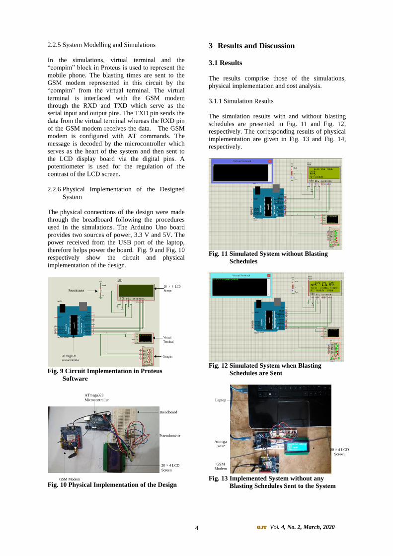
2.2.5 System Modelling and Simulations
In the simulations, virtual terminal and the
“compim” block in Proteus is used to represent the
mobile phone. The blasting times are sent to the
GSM modem represented in this circuit by the
“compim” from the virtual terminal. The virtual
terminal is interfaced with the GSM modem
through the RXD and TXD which serve as the
serial input and output pins. The TXD pin sends the
data from the virtual terminal whereas the RXD pin
of the GSM modem receives the data. The GSM
modem is configured with AT commands. The
message is decoded by the microcontroller which
serves as the heart of the system and then sent to
the LCD display board via the digital pins. A
potentiometer is used for the regulation of the
contrast of the LCD screen.
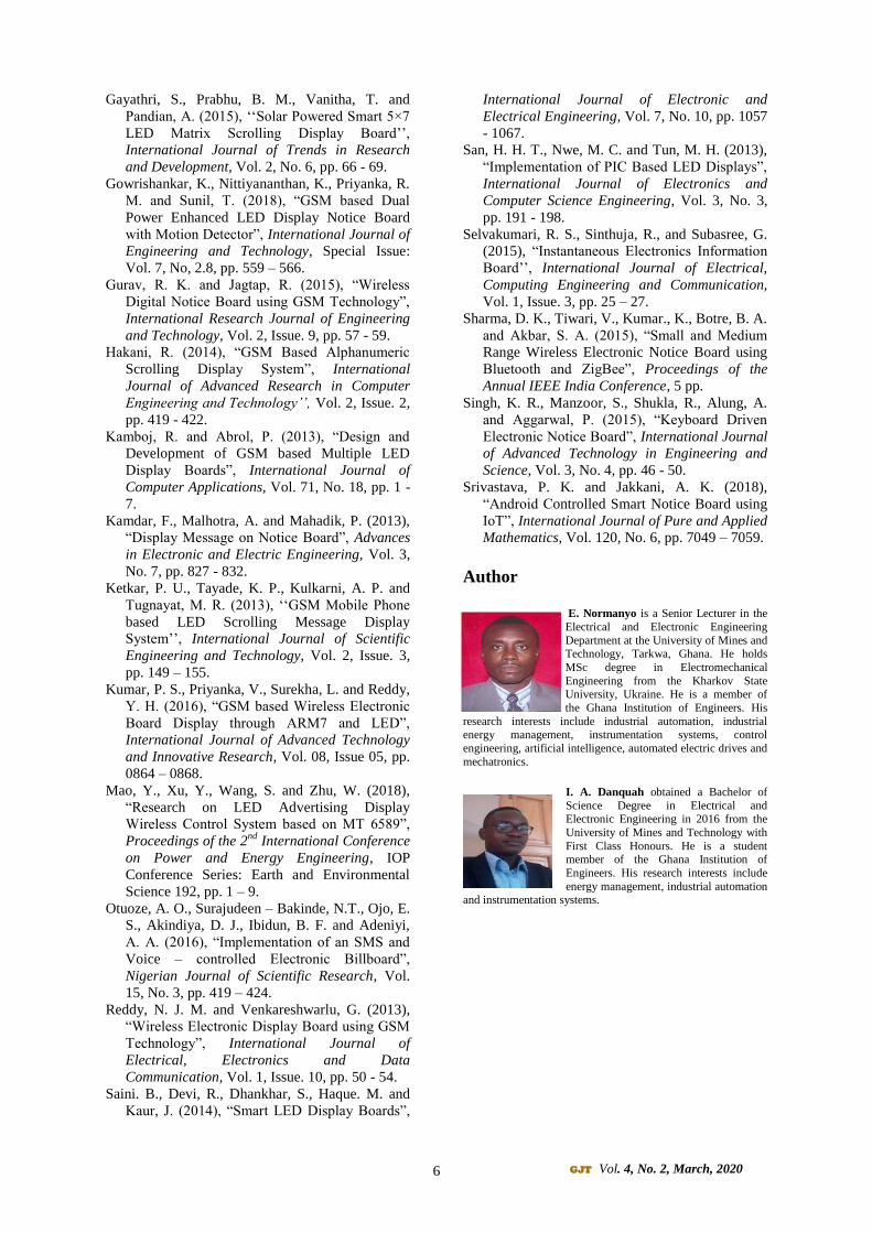
2.2.6 Physical Implementation of the Designed
System
The physical connections of the design were made
through the breadboard following the procedures
used in the simulations. The Arduino Uno board
provides two sources of power, 3.3 V and 5V. The
power received from the USB port of the laptop,
therefore helps power the board. Fig. 9 and Fig. 10
respectively show the circuit and physical
implementation of the design.
Fig. 9 Circuit Implementation in Proteus
Software
Fig. 10 Physical Implementation of the Design
3 Results and Discussion
3.1 Results
The results comprise those of the simulations,
physical implementation and cost analysis.
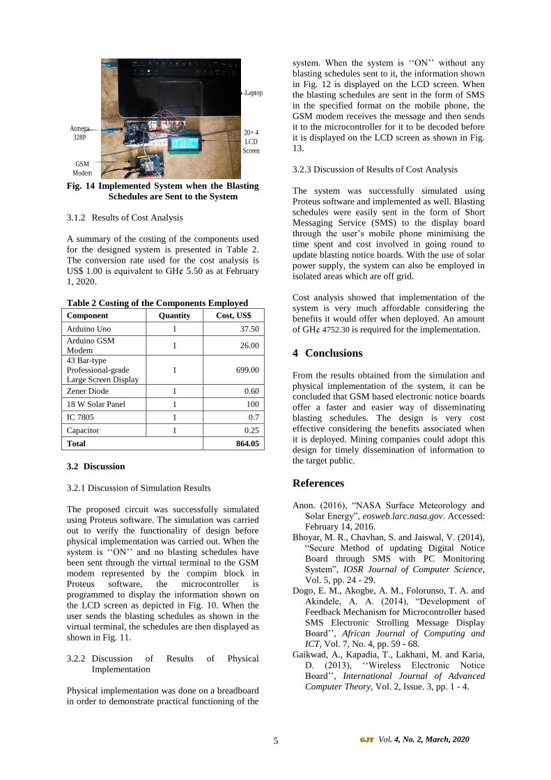
3.1.1 Simulation Results
The simulation results with and without blasting
schedules are presented in Fig. 11 and Fig. 12,
respectively. The corresponding results of physical
implementation are given in Fig. 13 and Fig. 14,
respectively.
Fig. 11 Simulated System without Blasting
Schedules
Fig. 12 Simulated System when Blasting
Schedules are Sent
Fig. 13 Implemented System without any
Blasting Schedules Sent to the System
20 × 4 LCD
Screen
Compim
Virtual
Terminal
ATmega328
microcontroller
Potentiometer
Breadboard
Potentiometer
20 × 4 LCD
Screen
GSM Modem
ATmega328
Microcontroller
20 × 4 LCD
Screen
GSM
Modem
Atmega
328P
Laptop
5 GJT Vol. 4, No. 2, March, 2020
Fig. 14 Implemented System when the Blasting
Schedules are Sent to the System
3.1.2 Results of Cost Analysis
A summary of the costing of the components used
for the designed system is presented in Table 2.
The conversion rate used for the cost analysis is
US$ 1.00 is equivalent to GHȼ 5.50 as at February
1, 2020.
Table 2 Costing of the Components Employed
Component Quantity Cost, US$
Arduino Uno 1 37.50
Arduino GSM
Modem 1 26.00
43 Bar-type
Professional-grade
Large Screen Display
1 699.00
Zener Diode 1 0.60
18 W Solar Panel 1 100
IC 7805 1 0.7
Capacitor 1 0.25
Total 864.05
3.2 Discussion
3.2.1 Discussion of Simulation Results
The proposed circuit was successfully simulated
using Proteus software. The simulation was carried
out to verify the functionality of design before
physical implementation was carried out. When the
system is ‘‘ON’’ and no blasting schedules have
been sent through the virtual terminal to the GSM
modem represented by the compim block in
Proteus software, the microcontroller is
programmed to display the information shown on
the LCD screen as depicted in Fig. 10. When the
user sends the blasting schedules as shown in the
virtual terminal, the schedules are then displayed as
shown in Fig. 11.
3.2.2 Discussion of Results of Physical
Implementation
Physical implementation was done on a breadboard
in order to demonstrate practical functioning of the
system. When the system is ‘‘ON’’ without any
blasting schedules sent to it, the information shown
in Fig. 12 is displayed on the LCD screen. When
the blasting schedules are sent in the form of SMS
in the specified format on the mobile phone, the
GSM modem receives the message and then sends
it to the microcontroller for it to be decoded before
it is displayed on the LCD screen as shown in Fig.
13.
3.2.3 Discussion of Results of Cost Analysis
The system was successfully simulated using
Proteus software and implemented as well. Blasting
schedules were easily sent in the form of Short
Messaging Service (SMS) to the display board
through the user’s mobile phone minimising the
time spent and cost involved in going round to
update blasting notice boards. With the use of solar
power supply, the system can also be employed in
isolated areas which are off grid.
Cost analysis showed that implementation of the
system is very much affordable considering the
benefits it would offer when deployed. An amount
of GHȼ 4752.30 is required for the implementation.
4 Conclusions
From the results obtained from the simulation and
physical implementation of the system, it can be
concluded that GSM based electronic notice boards
offer a faster and easier way of disseminating
blasting schedules. The design is very cost
effective considering the benefits associated when
it is deployed. Mining companies could adopt this
design for timely dissemination of information to
the target public.
References
Anon. (2016), “NASA Surface Meteorology and
Solar Energy”, eosweb.larc.nasa.gov. Accessed:
February 14, 2016.
Bhoyar, M. R., Chavhan, S. and Jaiswal, V. (2014),
“Secure Method of updating Digital Notice
Board through SMS with PC Monitoring
System”, IOSR Journal of Computer Science,
Vol. 5, pp. 24 - 29.
Dogo, E. M., Akogbe, A. M., Folorunso, T. A. and
Akindele, A. A. (2014), “Development of
Feedback Mechanism for Microcontroller based
SMS Electronic Strolling Message Display
Board’’, African Journal of Computing and
ICT, Vol. 7, No. 4, pp. 59 - 68.
Gaikwad, A., Kapadia, T., Lakhani, M. and Karia,
D. (2013), ‘‘Wireless Electronic Notice
Board’’, International Journal of Advanced
Computer Theory, Vol. 2, Issue. 3, pp. 1 - 4.
Laptop
20× 4
LCD
Screen
GSM
Modem
Atmega
328P
6 GJT Vol. 4, No. 2, March, 2020
Gayathri, S., Prabhu, B. M., Vanitha, T. and
Pandian, A. (2015), ‘‘Solar Powered Smart 5×7
LED Matrix Scrolling Display Board’’,
International Journal of Trends in Research
and Development, Vol. 2, No. 6, pp. 66 - 69.
Gowrishankar, K., Nittiyananthan, K., Priyanka, R.
M. and Sunil, T. (2018), “GSM based Dual
Power Enhanced LED Display Notice Board
with Motion Detector”, International Journal of
Engineering and Technology, Special Issue:
Vol. 7, No, 2.8, pp. 559 – 566.
Gurav, R. K. and Jagtap, R. (2015), “Wireless
Digital Notice Board using GSM Technology”,
International Research Journal of Engineering
and Technology, Vol. 2, Issue. 9, pp. 57 - 59.
Hakani, R. (2014), “GSM Based Alphanumeric
Scrolling Display System”, International
Journal of Advanced Research in Computer
Engineering and Technology’’, Vol. 2, Issue. 2,
pp. 419 - 422.
Kamboj, R. and Abrol, P. (2013), “Design and
Development of GSM based Multiple LED
Display Boards”, International Journal of
Computer Applications, Vol. 71, No. 18, pp. 1 -
7.
Kamdar, F., Malhotra, A. and Mahadik, P. (2013),
“Display Message on Notice Board”, Advances
in Electronic and Electric Engineering, Vol. 3,
No. 7, pp. 827 - 832.
Ketkar, P. U., Tayade, K. P., Kulkarni, A. P. and
Tugnayat, M. R. (2013), ‘‘GSM Mobile Phone
based LED Scrolling Message Display
System’’, International Journal of Scientific
Engineering and Technology, Vol. 2, Issue. 3,
pp. 149 – 155.
Kumar, P. S., Priyanka, V., Surekha, L. and Reddy,
Y. H. (2016), “GSM based Wireless Electronic
Board Display through ARM7 and LED”,
International Journal of Advanced Technology
and Innovative Research, Vol. 08, Issue 05, pp.
0864 – 0868.
Mao, Y., Xu, Y., Wang, S. and Zhu, W. (2018),
“Research on LED Advertising Display
Wireless Control System based on MT 6589”,
Proceedings of the 2nd
International Conference
on Power and Energy Engineering, IOP
Conference Series: Earth and Environmental
Science 192, pp. 1 – 9.
Otuoze, A. O., Surajudeen – Bakinde, N.T., Ojo, E.
S., Akindiya, D. J., Ibidun, B. F. and Adeniyi,
A. A. (2016), “Implementation of an SMS and
Voice – controlled Electronic Billboard”,
Nigerian Journal of Scientific Research, Vol.
15, No. 3, pp. 419 – 424.
Reddy, N. J. M. and Venkareshwarlu, G. (2013),
“Wireless Electronic Display Board using GSM
Technology”, International Journal of
Electrical, Electronics and Data
Communication, Vol. 1, Issue. 10, pp. 50 - 54.
Saini. B., Devi, R., Dhankhar, S., Haque. M. and
Kaur, J. (2014), “Smart LED Display Boards”,
International Journal of Electronic and
Electrical Engineering, Vol. 7, No. 10, pp. 1057
- 1067.
San, H. H. T., Nwe, M. C. and Tun, M. H. (2013),
“Implementation of PIC Based LED Displays”,
International Journal of Electronics and
Computer Science Engineering, Vol. 3, No. 3,
pp. 191 - 198.
Selvakumari, R. S., Sinthuja, R., and Subasree, G.
(2015), “Instantaneous Electronics Information
Board’’, International Journal of Electrical,
Computing Engineering and Communication,
Vol. 1, Issue. 3, pp. 25 – 27.
Sharma, D. K., Tiwari, V., Kumar., K., Botre, B. A.
and Akbar, S. A. (2015), “Small and Medium
Range Wireless Electronic Notice Board using
Bluetooth and ZigBee”, Proceedings of the
Annual IEEE India Conference, 5 pp.
Singh, K. R., Manzoor, S., Shukla, R., Alung, A.
and Aggarwal, P. (2015), “Keyboard Driven
Electronic Notice Board”, International Journal
of Advanced Technology in Engineering and
Science, Vol. 3, No. 4, pp. 46 - 50.
Srivastava, P. K. and Jakkani, A. K. (2018),
“Android Controlled Smart Notice Board using
IoT”, International Journal of Pure and Applied
Mathematics, Vol. 120, No. 6, pp. 7049 – 7059.
Author
E. Normanyo is a Senior Lecturer in the
Electrical and Electronic Engineering
Department at the University of Mines and Technology, Tarkwa, Ghana. He holds
MSc degree in Electromechanical
Engineering from the Kharkov State University, Ukraine. He is a member of
the Ghana Institution of Engineers. His
research interests include industrial automation, industrial energy management, instrumentation systems, control
engineering, artificial intelligence, automated electric drives and
mechatronics.
I. A. Danquah obtained a Bachelor of
Science Degree in Electrical and Electronic Engineering in 2016 from the
University of Mines and Technology with
First Class Honours. He is a student member of the Ghana Institution of
Engineers. His research interests include
energy management, industrial automation and instrumentation systems.