application of ripper-dozer combination in surface mines - ethesis
61
APPLICATION OF RIPPER-DOZER COMBINATION IN SURFACE MINES: ITS APPLICABILITY AND PERFORMANCE STUDY A THESIS SUBMITTED IN PARTIAL FULFILLMENT OF THE REQUIREMENTS FOR THE DEGREE OF BACHELOR IN TECHNOLOGY IN MINING ENGINEERING BY RAJAT KUMAR SAHU 108MN010 DEPARTMENT OF MINING ENGINEERING NATIONAL INSTITUTE OF TECHNOLGY ROURKELA-769008 2012
Transcript of application of ripper-dozer combination in surface mines - ethesis

APPLICATION OF RIPPER-DOZER COMBINATION IN
SURFACE MINES: ITS APPLICABILITY AND
PERFORMANCE STUDY
A THESIS SUBMITTED IN PARTIAL FULFILLMENT OF THE REQUIREMENTS FOR
THE DEGREE OF
BACHELOR IN TECHNOLOGY
IN
MINING ENGINEERING
BY
RAJAT KUMAR SAHU
108MN010
DEPARTMENT OF MINING ENGINEERING
NATIONAL INSTITUTE OF TECHNOLGY
ROURKELA-769008
2012

APPLICATION OF RIPPER-DOZER COMBINATION IN
SURFACE MINES: ITS APPLICABILITY AND
PERFORMANCE STUDY
A THESIS SUBMITTED IN PARTIAL FULFILLMENT OF THE REQUIREMENTS FOR
THE DEGREE OF
BACHELOR IN TECHNOLOGY
IN
MINING ENGINEERING
BY
RAJAT KUMAR SAHU
108MN010
Under the guidance of
PROF. H.K.NAIK
DEPARTMENT OF MINING ENGINEERING
NATIONAL INSTITUTE OF TECHNOLGY
ROURKELA-769008
2012

i
NATIONAL INSTITUTE OF TECHNOLGY
ROURKELA
CERTIFICATE
This is to certify that the thesis entitled “APPLICATION OF RIPPER-DOZER
COMBINATION IN SURFACE MINES: ITS APPLICABILITY AND PERFORMANCE
STUDY” submitted by Sri Rajat Kumar Sahu in partial fulfillment of the requirements for the
award of Bachelor of Technology degree in Mining Engineering at National Institute of
Technology, Rourkela (Deemed University) is an authentic work carried out by him under my
supervision and guidance.
To the best of my knowledge, the matter embodied in the thesis has not been submitted to any
other University/Institute for the award of any Degree or Diploma.
Date : Prof. H.K.NAIK Dept. of Mining Engineering
National Institute of Technology
Rourkela – 769008

ii
ACKNOWLEDGEMENT
First and foremost, I express my profound gratitude and indebtedness to Prof. H.K.Naik ,
Department of Mining Engineering for allowing me to carry on the present topic “Application
of ripper-dozer combination in surface mines: its applicability and performance study” and
his able guidance and pain taking effort in improving my understanding in this project.
Assemblage of this nature could never have been attempted without the reference to and
inspiration from the works of others whose details are mentioned in the reference section. I
acknowledge my indebtedness to all of them.
At last, my sincere thanks to all my friends who have patiently extended all sorts of helps for
accomplishing this assignment.
Date : RAJAT KUMAR SAHU

iii
CONTENTS
Page No.
CERTIFICATE i
ACKNOWLEDGEMENT ii
ABSTRACT v
LIST OF FIGURES vi
LIST OF TABLES vii
1. INTRODUCTION
1.1 Background 1
1.2 Objective 1
1.3 Research technique 1
2. LITERATURE REVIEW
2.0 Background 3
2.1 Reasons to select ripping 4
2.2 Rippability assessment- A review
2.3 Determining rippability
2.3.1 Direct methods 8
2.3.2 Indirect methods 10
2.3.3 Laboratory tests 13
2.4 Ripping techniques 15
2.5 Types of rippers 16
2.6 Ripping mechanism 19
2.7 Dozer blade. 21
3. SELECTION OF RIPPER DOZER 22
4. FIELD STUDY 1: PANCHPATMALI BAUXITE MINES,NALCO
4.1 Introduction 24
4.2 Location 25
4.3 Relief of terrain 25
4.4 Geology of the area 26
4.5 Mining method 26
4.6 Drilling and Blasting operation 28

iv
4.7 Selection for blast free mining 31
4.8 Specification of KOMATSU D475A ripper dozer 32
4.9 Cost Calculation
4.9.1 Cost calculation for drilling and blasting per tonne 36
4.9.2 Cost calculation for ripping per tonne. 38
4.10 Dozing operation 40
4.11 Drawbacks of ripping 41
4.12 Conclusion 41
5. FIELD STUDY 2: TALABIRA-1 OCP COAL MINES, HINDALCO
5.1 Introduction 42
5.2 Geo-mining condition 42
5.3 Salient features of Talabira-1 OCP 44
5.4 Parameters of overburden and coal benches 44
5.5 Selection and use of ripper dozer in Talabira-1 OCP 45
5.6 Cost calculation
5.6.1 Ripping cost calculation per tonne of OB 46
5.6.2 Drilling and blasting cost per tonne of OB produced 47
5.7 Conclusion 47
6. RECENT DEVELOPMENTS IN FIELD OF RIPPING & DOZING 48
7. CONCLUSION 50
REFERENCES 51
v
ABSTRACT
The surface mining of rocks and coal requires drilling and blasting operation for loosening the
strata. In drilling and blasting a lot of dust, gases, ground vibrations, cracks and noise are
produced. This concludes that these operations are not eco -friendly. Also they involve many
types of machinery to complete the job. Blast free mining is the need of the hour to conserve the
environment. Different studies and experiments have come up with developments like Ripper
dozer and Surface miner. Ripper is mainly used to excavate the overburden. These involve less
number of machinery. But before deploying rippers in mines, proper rippability assessment of
the strata should be done. There are different parameters on which rippability of rocks depend
on. Relationships are made between the parameters and productivity of rippers. Considering all
these parameters rippers are introduced in mines.

vi
LIST OF FIGURES
Figure no. Name Page 2.1
Different excavation techniques considering various types of strata 6
2.2 Seismic velocities in relation to ripping 8
2.3 Triangular cross section cut
9
2.4 Excavability based on Rebound no.( R) and compressive
strength(qu)
10
2.5 Ripping capacities (in term of power and seismic velocity) 12
2.6 Laboratory ripping machine 13
2.7 Relation between specific energy and hourly production of ripper 14
2.8 Hinge type ripper 17
2.9 Parallelogram type ripper 17
2.10 Adjustable parallelogram type 18
2.11 Adjustable radial type 18
2.12 Modes of achievement of initial penetration of tyne 19
2.13 Different ripping mechanisms 20
4.1 Panchpatmali bauxite mines Mining and reclamation 28
4.2 Komatsu D-475A ripper dozer 33
6.1 Dozer being remotely controlled 48

vii
LIST OF TABLES
Table
no.
Topic Page
2.1 Factors suggested by different researchers 5
2.2 Excavation characteristics based on rock strength and hardness 7
2.3 Excavation characteristics based on joint spacing 7
2.4 The relationships between rock properties and specific energy 14
2.5 Drawbar pull for consecutive speed 15
3.1 General relationship between ease of ripping and producivity 22
3.2 Extended rippability classes of marls 22
3.3 Typical specifications of various rippers from the Caterpillar
Company.
23
4.1 The results of the seismic velocity by NGRI Hyderabad 31
4.2 The physico-mechanical properties of various types of rock at
Panchpatmali bauxite mines study by IIT Kharagpur
32
4.3 Cost calculation for drilling per MT 36
4.4 Cost of blasting per T (tonne) with gel explosive 37
4.5 Ripping cost per T (tonne)
39
5.1 Geo-mining condition of Talabira-1 block 43
5.2 Parameters of the Ob and coal benches 44
5.3 Ripping cost per tonne of OB 46

1 | P a g e
Chapter 01
INTRODUCTION
1.1 Background :
Archaeological studies say that mining was done during in prehistoric times in stone age. Great
progress was made in the field of mining when the concept of black powder reached far west,
probably from China in the late middle ages. This was replaced by dynamite and gradually
shifted to ammonium nitrate fuel blasting agents and slurries. Proper breakage of rocks require
correct hole placement and blasting order.
Development in drilling techniques was accompanied by developments in loading and
excavation techniques. Now-a-days deposits at greater depth have been attacked by surface
mining methods. The share of opencast methods has gone upto 70% of world’s total mineral
production.
The surface mining of hard rocks and ore demands drilling and blasting. But these techniques
have many adverse effects on environment. So today’s eco-conscious world demands
introduction of improved technology for blast free, safe and eco-friendly mining.
Ripper with dozer can be an appropriate answer to the present trend blast free eco-friendly
mining. It results in minimized use of explosives for very hard strata.
1.2 Objective:
The basic objective is to study the applicability and performance of ripper-dozer combination in
both coal and metal opencast mines and suggest some recent developments.
1.3 Research technique:
I. Extensive literature review has been done to identify the parameters affecting the
performance of ripper-dozer. The role of these parameters and how they are affecting are
established in this study.

2 | P a g e
II. Two case studies have been done to study the performance of ripper dozer. Cases of
Panchpatmali Bauxite mines, NALCO, Damanjodi and Talabira-1 coal OCP,
HINDALCO, Talabira have been studied.
III. Recent developments in the field of ripping and dozing have been mentioned in this
report.

3 | P a g e
Chapter 02
LITERATURE REVIEW
2.0 Background:
Ripping with dozers came into existence in late 1950s and have become popular method of
excavating soil and rock. Mostly it is used to excavate overburden. Ripping is method of
loosening rocks using steel tynes attached to the rear of bulldozers. These tynes are lowered into
the ground which displaces the soil or blocks of rocks as the whole unit moves forward.
Ripping is usually economic than drilling and blasting. But as the ripping becomes harder
drilling and blasting becomes cheaper. The problems of noise and dust pollution by the fly rock
and the ground vibration in blasting area has caused serious concern to the environmentalist and
the laws as in different countries have laid down strict limits for them. With the evolution of high
power rippers this has been made possible and as it stand today ripper dozer while taking care of
environment and safety have become competitor to drilling and blasting even in term of cost.
The ripper has a long recorded history as it was the first means for fragmenting the rock in situ.
The evolution of rippers can be dated back to 312 B.C when a wheel mounted plough drawn by
oxen was used for building the Roman Appian way the rippers drawn by tractors with about 75
H.P with the passage of time developments have undergone several technological developments
and today we have the heaviest ripper weighing about 92965 kg being pulled by the 770 H.P
tractor.

4 | P a g e
2.1 Reasons to select ripping:
Ripping is considered due to various reasons as stated below:
Increased productivity: In ripping process there is continuous work going on. This
reduces idle time. It also eliminates shifting of machines which present in blasting
operation.
Minimized ground vibration: Drilling and blasting operation includes large ground
vibration which affect nearby inhabitation and creates cracks on ground and structures.
Ripping and dozing minimizes ground vibration.
Safety: There are chances of generation of fly rocks during blasting. Also chances of
misfires are more in blasting operation. Ripping eliminates the chances of generation of
fly rocks and misfires, thereby increasing safety of life and properties.
Noise and dust reduction: Drilling and blasting creates a lot of noise and dust which is
eliminated by use of rippers.
Product size: Blasting sometimes result in oversize boulders which may require
secondary blasting which is a costly affair. But selection of right kind of ripper results in
right size of material.
Slope stability: blasting may result in slope failure. But ripping provides better safety
and slope stability.
Quality control: In blasting there are chances of dilution of ore. But in ripping operator
can easily distinguish between ore and waste. Ripping is helpful in selecting mining.
Cost economics: Ripping doesn’t involve involvement of various machineries as in
drilling and blasting thereby making the process economical.
Environmental friendly: Ripper provides a pollution free environment to work.
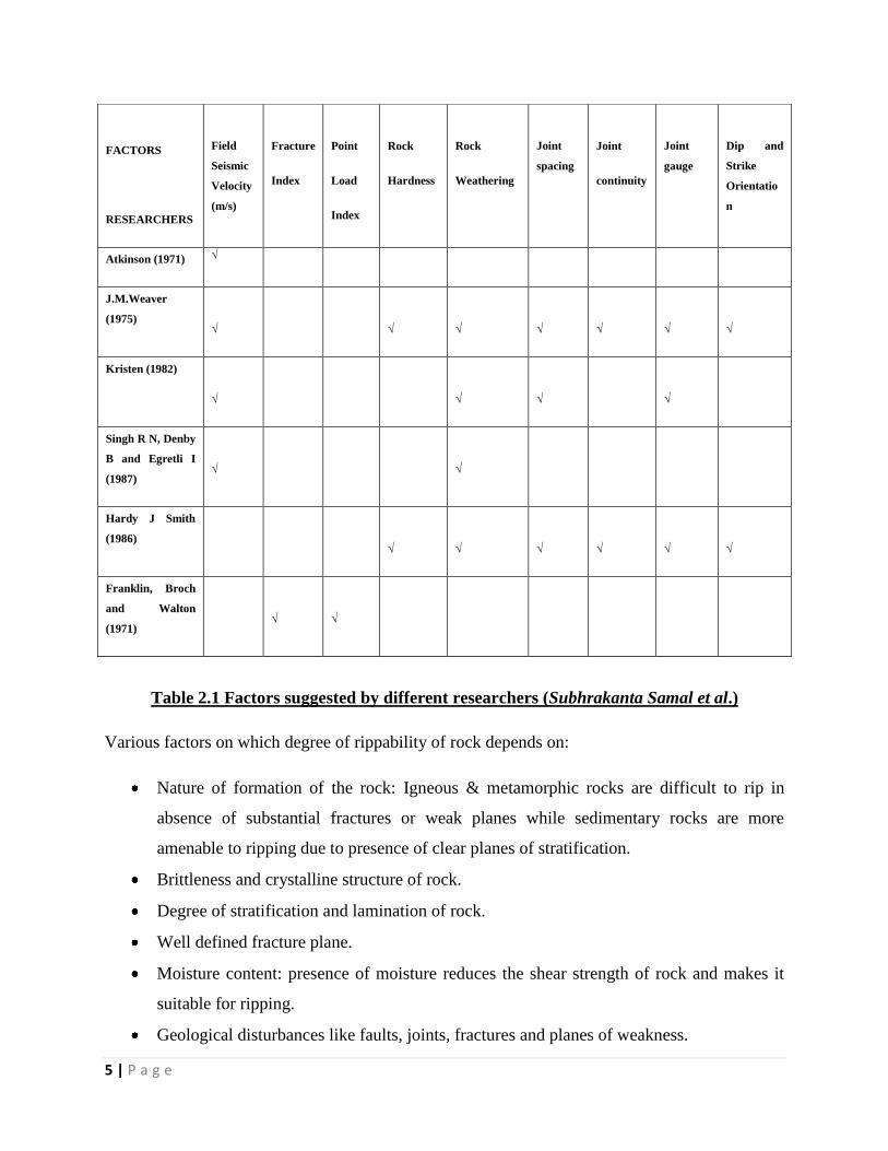
2.2 Rippability assessment- A review
Selection of ripper depends on degree of rippability of rock. There is lot of factors on which
degree of rippability depends on. Many researchers have suggested many factors. Following is
table showing various factors proposed by different researchers.
5 | P a g e
Table 2.1 Factors suggested by different researchers (Subhrakanta Samal et al.)
Various factors on which degree of rippability of rock depends on:
Nature of formation of the rock: Igneous & metamorphic rocks are difficult to rip in
absence of substantial fractures or weak planes while sedimentary rocks are more
amenable to ripping due to presence of clear planes of stratification.
Brittleness and crystalline structure of rock.
Degree of stratification and lamination of rock.
Well defined fracture plane.
Moisture content: presence of moisture reduces the shear strength of rock and makes it
suitable for ripping.
Geological disturbances like faults, joints, fractures and planes of weakness.
FACTORS
RESEARCHERS
Field
Seismic
Velocity
(m/s)
Fracture
Index
Point
Load
Index
Rock
Hardness
Rock
Weathering
Joint
spacing
Joint
continuity
Joint
gauge
Dip and
Strike
Orientatio
n
Atkinson (1971) √
J.M.Weaver
(1975)
√
√
√
√
√
√
√
Kristen (1982)
√
√
√
√
Singh R N, Denby
B and Egretli I
(1987)
√
√
Hardy J Smith
(1986)
√
√
√
√
√
√
Franklin, Broch
and Walton
(1971)
√
√

6 | P a g e
Grain size: coarser the grain-size more it is suitable for ripping.
Degree of consolidation of rock.
Physico-mechanical properties of rocks like compressive strength tensile strength, shear
strength rocks having higher compressive strength require high power ripper for breaking
them.
Specific energy (Basarir H., et al, 2004).
Fig.2.1 Different excavation techniques considering various types of strata.

7 | P a g e
Table 2.2 Excavation characteristics based on rock strength and hardness. (Rock
excavation techniques, MnE-415 course notes, university of Arizona mining and geological
engineering.)
Table 2.3. Excavation characteristics based on joint spacing (Rock excavation techniques,
MnE-415 course notes, university of Arizona mining and geological engineering.)

8 | P a g e
Fig.2.2. Seismic velocities in relation to ripping (Source: Caterpillar,2008 ).
2.3 Determining rippablity
Rippability can be determined in two methods:
i) Direct methods
ii) Indirect methods
2.3.1 Direct method:
It includes direct field trials at the site with available equipment. The ripper performance is
determined based on hourly production rate, Qh in m3/hr, which is either determined by volume
by weight, volume by cross sectioning, and volume by length method (Basarir and Karpuz,
2004). Hourly production depends on ripper horsepower and in-situ rock properties.
Volume by length method: Hourly production is calculated as follows:
Hourly production rate, Qh = Qc x 60 x E /t
Where, Qc – Production per cycle, m3/hour (on bank volume)
E – Operator’s efficiency
t – Cycle time, minutes
9 | P a g e
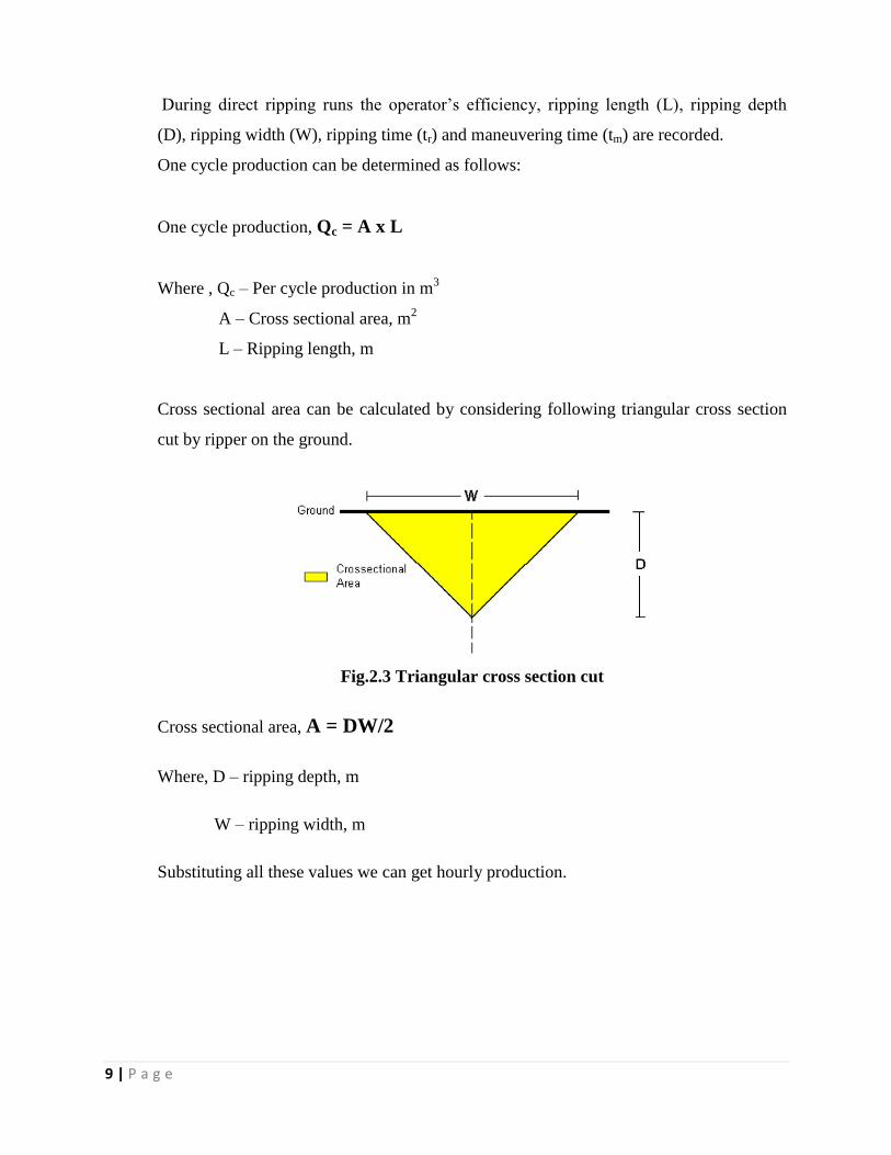
During direct ripping runs the operator’s efficiency, ripping length (L), ripping depth
(D), ripping width (W), ripping time (tr) and maneuvering time (tm) are recorded.
One cycle production can be determined as follows:
One cycle production, Qc = A x L
Where , Qc – Per cycle production in m3
A – Cross sectional area, m2
L – Ripping length, m
Cross sectional area can be calculated by considering following triangular cross section
cut by ripper on the ground.
Fig.2.3 Triangular cross section cut
Cross sectional area, A = DW/2
Where, D – ripping depth, m
W – ripping width, m
Substituting all these values we can get hourly production.

10 | P a g e
2.3.2 Indirect methods:
These methods utilize the material properties and rock mass. They are divided into ‘graphical’,
‘seismic’ and ‘graphical’ methods (Basarir H, et al). Graphical method is used during planning
stage of major work. Figure 2.2 and 2.4 shows performance of ripper based on various material
properties and seismic velocity of the strata.
Source (McLean & Gribble, 1985)
Fig.2.4 Excavability based on Rebound no.( R) and compressive strength(qu)
11 | P a g e
Seismic wave analysis:
The seismic wave analysis is based on the principle of propagation of sound waves through
different sections of rock. It is known that sound waves travel sub-surface material at different
velocities, depending upon the degree of consolidation of the material. Poorly consolidated
materials with low seismic velocity are easily rippable than highly consolidated material with
high seismic velocity.
The seismic velocity analysis is accomplished by use of Refraction seismograph. The equipment
includes a source of sound or shock wave, a receiver, an electric counter, and a set of cables.
For performing the survey, all benches are surveyed to measure the compressional wave seismic
velocities (P-wave) to aid in the evaluation of the rippability of the sub surface. The instrument
called Geode (Make: Geometrics controllers Inc., USA) is used for acquiring the seismic data
and the method of profiling is carried out.
Surface wave tomography is an efficient way to obtain images of the group velocity at at a test
area, because Rayleigh-wave group velocity depends on frequency. There are separate images
for each frequency and at each point in these images the group velocities define dispersion curve
which relates group velocity to frequency. Detection and imaging requires a multichannel
approach to data acquisition and processing. Integrating Multichannel Analysis of Surface
Waves (MASW) method with a Common Mid-Point (CMP) style data acquisition permits the
generation of a laterally continuous 2D shear wave velocity field cross section (Park et al., 1999;
Xia et al., 1999). Mating MASW with CMP provides a non-invasive method of delineating
horizontal and vertical variations in near-surface material properties. ( M.Ramulu et al., 2012).
Continuous acquisition of MASW data along linear transects has recently shown great promise
in detecting shallow voids and tunnels, mapping the bed rock surface, locating remnants of
underground mines and delineating structures (Park et al.,1999). Extending this technology from
sporadic sampling to continuous imaging required the incorporation of MASW and CDP
(Mayne, 1962). Integrating these technologies result in generation of 2D cross section of the
shear wave velocity field. This cross section contains information about horizontal and vertical
continuity and physical properties of materials at shallow depths. Seismic reflection surveys are

12 | P a g e
generally designed to image structural and stratigraphic features with a high degree of resolution
and accuracy. The surface waves are considered noise.
The seismic wave velocity is recorded in m/s and the tests help in determining the following:
a) Depth to unconsolidated layer such as bed rock gravel or clay
b) Thickness of the intermediate layers assuming each becomes progressively harder
c) Approximate density of each layers degree of consolidation leading to identification of
material type
d) Location of faults, fractures and other irregularities in the formation
Fig.2.5 Ripping capacities (in term of power and seismic velocity)

13 | P a g e
2.3.3 Laboratory tests:
Laboratory experiments are done to determine the uniaxial compressive strength (UCS), indirect
tensile strength (ITS), unit weight (d), and point load strength index tests (Is50).
Laboratory ripping runs tests is performed on laboratory ripping machines as shown in fig 2.6.
This machine simulates working of a single shank ripper with rating 1850 rpm, and cutting speed
of 150m/s (Mohd For Mohd Amin, 2008).
Specially designed cutting shank is used to make a V-cut in rock samples. The required power is
noted down. The result is in terms of specific energy in MJ/m3. Using the length of the cut (L) in
meters, density of material produced, and volume of the material cut in m3 is calculated.
Considering force (F) measured in mega Newtons (MN)
The specific energy (SE) is,
SE = FL/V
Fig 2.6 Laboratory ripping machine.
The specific energies can be related to various rock parameters as shown in the table 2.4

14 | P a g e
Table 2.4. The relationships between rock properties and specific energy (H Basarir et al,
2008)
The relation between specific energy and hourly production of ripper is shown in the following
graph.
Fig.2.7 Relation between specific energy and hourly production of ripper (H Basarir et al,
2008)

15 | P a g e
2.4 Ripping techniques:
The suitable technique depends on the job conditions. Following factors are to be considered
before selecting proper ripping technique.
a) Ripping speed: Proper gear and speed plays important role in maximization of ripping
production. Generally first gear with a speed of 1-1.5mph gives the economical
production with maximum drawbar pull. Excessive speed causes track slippage and rapid
undercarriage wear as well as tip wear. Excessive speed heats up the tip thereby
decreasing the life of the tip.
Speed in MPH Drawbar HP
0.5
324.00
1.0
466.00
1.5
510.00
2.0
410.00
2.5
490.00
3.0
480.00
5.0
466.67
Table 2.5 Drawbar pull for consecutive speed (P K Panda & S K Misra, 1989)

16 | P a g e
b) Ripping depth: Ripping depth is a function of job condition, material hardness,
lamination thickness, and degree of fracturing. Ripping should be done at maximum
depth allowable by the ripper. When considerable stratification is encountered it is
preferable to rip at partial depth and remove the material in its natural layer rather than to
take out a full ripped layer. Where scrapers are used to lift materials to the dumpers it is
advisable to rip to a uniform depth eliminating the hard rocks which can lift off the
scraper edged from the ground.
c) Spacing between the passes: Optimum spacing between the passes helps in maximizing
the production. Closer the spacing, smaller is the chunk size. When full penetration
occurs, pass spacing of one-half the tractor width allows the track to move over the
material just ripped and increasing the crushing of the same.
d) Ripping direction: The ripping direction is decided by the job layout. When scrapers are
used to remove material ripping should be done in the direction scraper loading in order
to increasing the scraper loading efficiency. When vertical laminations or fractures are
found on the rock formations ripping is done across the cuts. Downhill ripping is
preferred as it takes the advantage of the tractor weight and horsepower.
2.5 Types of Rippers: (P K Panda & S K Misra, 1989)
Following types of ripper dozers are available:
1) Hinge type
2) Parallelogram type
3) Adjustable parallelogram type
4) Adjustable radial type
5) Impact ripper.
1) Hinge type:
In this type the linkage carrying the beam and the shank pivots at the rear end of the ripper. It
uses a beam with one or more pockets to hold one to five shanks. Each pocket allows upto five
different shank positions to adjust depth and tooth angle to meet various condition. Hinge type

17 | P a g e
provides the advantage of aggressive tooth entry angle but cannot be adjusted for varying rock
conditions.
Fig.2.8 Hinge type ripper (P K Panda & S K Misra, 1989).
2) Parallelogram type:
Here the linkage maintains the same tip ground angle regardless of tooth depth, hence excellent
penetration characteristics. Single shank rippers are used specially for hard ripping where greater
ripping depth is required. The clearance between the tracks and the shanks is more in cseof
parallelogram type than hinge type. The ripper is in raised position which helps the operator to
see the tip damage or loss thereby avoiding damage to the shank from ripping.
Fig. 2.9 Parallelogram type ripper

18 | P a g e
3) Adjustable parallelogram type
This shares the features of hinge type and parallelogram type. It can vary the tip angle beyond
vertical for improved penetration and can be hydraulically adjusted while ripping to provide the
optimum ripping angle.
Fig. 2.10 Adjustable parallelogram type
4) Adjustable radial type
It combines the features of hinge type with the shank angles from high angles. It provides more
aggressive shank penetration angle at start and optimum angle for advancement through material.
Fig.2.11 Adjustable radial type.
5) Impact type
Generally the drawbar force is limited by tractor engine horse power, power train, weight and
traction. In impact type engine power is converted to hydraulic power for operating an impact
which is then transferred to shank. This result in fracturing of rock thus increasing penetration,

19 | P a g e
reducing drawbar pull requirement and expanding range of rippable rock. With this type ripper it
is now possible to rip rocks having seismic velocity for 3000m/s.
2.6 Ripping mechanism
In the process of ripping, the ripper tip is lowered in to the ground by means of hydraulic forces
which continues till initial bit penetration is achieved. The initial penetration of the tip or tyne is
either occurred through the rock mass, defect planes or combination of both as shown in fig 2.12.
Fig.2.12 Modes of achievement of initial penetration of tyne
When the stress concentration of tip exceeds the compressive strength of the rock it causes shear
failure of rock allowing initial tip penetration. As tractor moves the penetration causes tensile
failure of rock. In case of jointed rocks the failure takes place due to failure of cohesive force
between the structural blocks.
There are basically five mechanisms of ripping (by Fiona Mac Gregor) as show in following fig
2.13. These include ploughing, loosening, crushing, tearing, splitting and prying out.

20 | P a g e
Fig. 2.13 Different ripping mechanisms.
Ripping mechanisms outlined by Darcy, 1971:
i) Ploughing: In dense material without bedding planes, a narrow road is plowed ,
displacing only a small amount of material.
ii) Crushing: in case of fractured rocks having small defect spacing (0.1-0.3m) material is
easily crushed, disorganized.
iii) Lifting: In horizontally stratified rocks, slabs are lifted by ripper causing breaking by
traction, bending and shearing.
iv) Breaking: Breaking takes place in case of inclined stratified rocks by shearing at the
point of the ripper by bending and lateral traction.

21 | P a g e
2.7 Dozer blade:
Ripper is also available with a pusher blade attachment. The dozer blade or the pusher blade
can be raised or lowered through small angles horizontally by rams operated through
hydraulic pressure or ropes. The blades are Used to push materials ripped or sand or soft
weathered rocks. A dozer can dig upto1.5m below the ground in earth or weathered rock.
There are different types of blades to suit different types of work, but most commonly used
are straight, universal and semi-universal. The straight blade comprises of mold board
slanting forward and concave in the front. It has a removable cutting edge at the bottom. The
universal blade has large wings on either side of central section. The semi-universal has
features in between the above two and short wings. The straight blade has higher capability
of better penetration and handling of heavier material. The universal blade is suited for larger
loads pushed over long distances. The wings prevent the spillage of materials. The semi-
universal blade provides improved load retention capability and better penetration in tighter
ground as compared to universal blade.
Output of dozer :
Q = 60Csµ/t
Where, Q- output in m3/h
C – dozer blade capacity
s – swell factor
µ - production efficiency
t – cycle efficiency

22 | P a g e
Chapter 03
SELECTION OF RIPPER- DOZER
There are various factors affecting the selection if rippers. However the seismic wave velocity
and productivity affects much. Also the specific energy plays an important role. Various studies
have been taking place. Relationship between specific energies, seismic wave velocity and
productivity has been established by various researchers.
Table 3.1. General relationship between ease of ripping and producivity ( by Fiona Mac
Gregor)
Following table suggest relationship between the specific energies and productivity of different
types of Caterpillar ripper dozers.
Table 3.2 Extended rippability classes of marls (by H. Basarir & C. Karpuz, 2004)
23 | P a g e
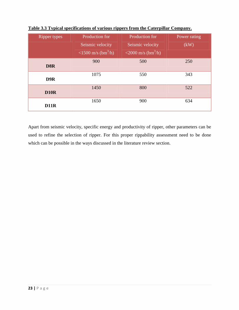
Table 3.3 Typical specifications of various rippers from the Caterpillar Company.
Ripper types Production for
Seismic velocity
<1500 m/s (bm3/h)
Production for
Seismic velocity
<2000 m/s (bm3/h)
Power rating
(kW)
D8R 900 500 250
D9R 1075 550 343
D10R 1450 800 522
D11R 1650 900 634
Apart from seismic velocity, specific energy and productivity of ripper, other parameters can be
used to refine the selection of ripper. For this proper rippability assessment need to be done
which can be possible in the ways discussed in the literature review section.

24 | P a g e
Chapter 04
FIELD STUDY 1: PACHPATMALI BAUXITE MINES, NALCO
4.1 Introduction:
Panchpatmali bauxite mines of national Aluminium Company Limited with a production of 4.8
Million tonnes of bauxite 1.6 Million tonnes of over burden with high capacity rippers has been
chosen as economic alternative to drilling and blasting. The bauxite deposits of Precambrian age
where the ore has been formed through a process of weathering and lateralization of the parent
rock (khondalites). The over burden is composed of hard ferruginous laterite extending in
thickness from 0 to 3.5 m with an layer extending in thickness in an irregular manner from 10 to
35m with an average thickness of 14mts.The average OB ratio is 1:0.3 over entire deposit.
The seismic wave velocity studies of different formation conducted by NGRI Hyderabad reveals
that vary from 1100m/s to 2600 m/s and 80% of deposit falls within the velocity range of 1100 -
1300 m/s 15% of the deposit falls within 1300 to 1800 m/s to 2600m/s and above. The study of
seismic wave velocities in the various formations of Panchpatmali deposit demonstrated the
amenability of the deposit for efficient and economic application of production ripping and
enabled the designers to select out of the available rippers suitable equipment sizes for rock
fragmentation in the mine.
4.2 Location
The Panchpatmali bauxite mine in the Koraput District of Orissa exploits the largest single
bauxite deposit in India having a reserve of 317 million tones of bauxite with a production
capacity of 4.8 million tones pre year. It is located 40 Kms from the Koraput District Head
quater on the national haighway NH-43 (connecting Raipur & Vizag). The Panchapatmali Hill
spans for a length of 21 Kms in NE-SW directions, bounded by latitudes 18046’ & 18
0 north &
longitude 820 57’ and 83
0 04’ east. The deposit constitutes the top of the Panchpatmali hill the
bauxite is confined between the elevations of 1154m &1366m above the mean sea level in the
three different blocks namely North, Central and South blocks, extending over an area of 16
sq.kms. The central block has been further divided into Sector-I and Sector –II.
25 | P a g e
4.3 Relief of the terrain
Panchpatmali hill forms a part of the Eastern Ghats range in general this area represents deserted
hill topography. Small hillocks and mounds are inter-spaced with narrow and deep valleys.
Panchpatmali is distinctly marked within this hilly terrain both in the field and in topo sheet
because of its height and extensive flat plateau land conspicuously this hill is continuous and
undisseccted compared to the adjoining hills of smaller dimensions.
Flat to gently rolling plateau top on Panchpatmali hill extends for a length of 21 km In NE-SW
direction. Few water sources cut the plateau width and flow to irregular laid out narrow steep
valleys and escarpments at the hill slopes. The width of plateau varies from more than 2000
meters to less than 100 meters with an average of 800 meters. The area is 16.8 sq. km.
The highest point on Panchpatmali stands at an elevation of 1336.7 meters above mean sea level
and 450 meters above the adjoining plains. The mean reduced level of plateau edge is around
1280 meters. It has steep escarpments for 10 meters to 50 meters on all the thereafter the slope is
gentle.
4.4 Geology of the area
The geological, structural and Lithological characteristics of Panchapatmali bauxite deposit and
secondary areas are same as other Eastern Ghats deposit. Bauxite bearing laterite capping which
occurs as a blanket cover over whole of Panchpatmali hill is formed in situ by weathering and
lateralization of khondalites the parent rock which lies below the lateritic formation the main
geological features are out lined below-
The rock types of the area belong to Khondalites and Chanockite series of the Eastern
Ghats and are of Precambrian age khondalites generally form high and liner ridges while
charnockites occur on lower slopes of the hills or the valleys.
Khondolites are granitic gneisses with quartz feldspar garnet, sillimanite corundum
opaque ore minerals limonite and graphite as the major mineral constitutes. Charnockites
of all types i.e. acidic, basic and intermediate types are observed in the area. Khondolites
with weak planes of line foliations cleavages joints etc. are more weathered and altered
compared to charnockites.

26 | P a g e
Relatively low mineralization thickness (13.3 m) on the whole compared to the
admissible bench height up to 12m.
Irregular mineralization thickness, generally between 8.5m and 18m sometimes more
than 20m particularly varying by a possible 5m over about 10m.
Small amount of sterile overburden averaging 3m in thickness, or only 18.4% of the total
thickness to be mined.
Simple relief with slopes generally less than 10% although steeper over 2/5 of the of the
deposit area.
Very irregular contact between ore and bottom due to the relief and more especially to
the irregularities in the mineralization thickness and overburden.
4.5 Mining method
Considering the deposit characteristic of Panchpatamali bauxite deposit “Trench Mining
Method” has been adopted for scientific extraction of Bauxite ore. This is a simple modification
of the conventional bench method of mining. This method drive for operating a number of
slightly absently trenches with staggered faces and floor at increasingly lower level form a
service road & normally advancing parallel to the longer axis of the plateau. The width
exceeding 40 m & different floor levels between adjacent trenches not exceeding 4 m.
The trench mining method of operation adopted in Panchpatmali Bauxite mine can be classified
into three basic phases.
1) Excavation of overburden
Overburden on the top of the mineralized Zone average (3m thick) comprising top soil and
laterite are mined in two stages. Top soil is directly excavated and loaded will ahead of laterite &
kept separately for using in plantation in reclaimed area. The laterite is mined on a single bench,
ahead of bauxite maintaining a lead of 75m. The low ratio of overburden to ore & the relative
softness of the rock handled to excavation or rocks breakage by ripping. Blasting is used in
addition to ripping in the harder formation rock breakage. After blasting or ripping the OB is
handled wheel loader & dozer to clean the mineralized top. The laterite overburden is loaded into
27 | P a g e
50/55 ton dumper by means of wheel loader. Then the dumpers carry the overburden to a
dumping area, where the Bauxite has already been mined out for reclamation.
2) Excavation of bauxite
The bauxite mining at present is carried out in two stages top bench mining & Bottom bauxite
mining. The top benches are excavated by drilling & blasting with average bench height of 8 m
Holes of 150 mm dia. drilled by DTH drill are Charged with indo–boost , indo-gel & blasted to
loosen the ore. The blasted mineral is loaded by the 8.7 m3 wheel loader into 50/55 ton dumpers
which carry it to the crusher. The bottom bench bauxite is mined selectively by using back hoe
for complete bauxite excavation. Both overburden & bauxite face advances in a number of
parallel trenches of varying width & levels.
The bauxite ore is crushed to 150mm size by a double roll toothed crusher & then transported to
Alumina plant through a single flight long distance cable belt conveyor system of 14.6 km
Length.
The trench method of mining has the following advantages-
Mining faces are separated, inter chargeable, are numerous & can be worked concurrently
for effective grade control of ROM feed.
Adaptability to geological disturbances on the deposit resulting in lower loss & dilution
factors.
Convenient work site dimensions permit concentration of mining equipment &
minimized travel time.
3) Reclamation of mined out area
Reclamation of mined out area is a concurrent process with ore mining in the trench mining
method. Once complete bauxite excavation is done the area is released for back filling by the
over burden consisting of fertile soil and laterite mined separately. First laterite is filled and

28 | P a g e
leveled then a thin layer of soil is covered on the top of it for plantation activities. Sumps and
reservoirs’ are also planned within this reclaimed area for collecting rain & surface runoff water
from mining areas which is allowed to the valleys after due sedimentation/ setting of mud.
SAB\mis2\ppt 16
Top Bxt.
Bottom. Bxt.
Top Soil
PLK
Laterite
Land Re clamation
& Plantation
Mining & Reclamation
Fig 4.1 Panchpatmali bauxite mines Mining and reclamation.
4.6 Drilling and blasting operation
The existing practice of Drilling & Blasting has been adopted since the inception of the mine
with lot of efforts, leading to optimum use of explosive energy. The non-rainy days and non-
watery holes use ANFO. ANFO is mixed by imported Mixing and delivering truck of very high
capacity. Cartridge and/or Cast booster is predominantly used as booster. In dry holes, cartridge
column charge is used with cartridge booster. The support system to store explosives, explosive
vans to carry explosives and accessories are quite systematic and observe all statutory provisions
as is laid in Indian Explosives Rules & Metalliferrous Mines regulation.
Major drawbacks:
1) Use and Storage of explosive- After naxal attack in the mines crores of money has been
invested not only for the security of the employees but more in Storage and transportation
of Explosive. It is very challenge for the C.I.S.F. Jawan to maintain security in the
magazine where explosive is stored. Recent times using explosive for mining operation

29 | P a g e
not only unsafe for the life of security force but also not advisable for economical point
of view.
2) Fragmentation- Generation of oversize boulders in blasting which cause jamming,
shear pin and downtime of crusher so necessitates of secondary breaking, first option
secondary blasting which is not done so rock breaker is the next option for handling over
size boulder. Sorting the oversize boulder while loading by wheel loader then breaking
in to required size by rock breaker need extra machine as well as manpower which cause
loss of working hour as well as unsafe to handle and un-productivity one.
3) Steep mining- Where the angle of dip of the bauxite deposit is more than 250 mainly
valley side it is not easy for drilling so dozer or loader is deployed for preparation of
platform for drilling and also to make the blasting face vertical for better output which is
uneconomical. Where the angle of dip is very steep drilling & blasting impossible so
need for ripper dozer operation
4) Ground vibration- one of the troublesome and controversial issues facing is that blast
induced ground vibration with general trend towards large blasting in mines, increased
population and spread of urban near to the mining site ground vibration problem
complain have risen manifolds so blasting near to structural building and valley site
villages is avoided
5) Impact on environment- Panchpatmali bauxite mines comes under forest region; bird
and wild animal of different species are found in this place. Heavy noise and ground
vibration scares away the animal and birds inhabiting the area it also harmful for human
beings as well.
Minor drawbacks-
1) In the process of rock blasting lot of dust as well as high level of noise is produced
which is harmful for the men.
2) Blasting results in back break and overhangs which are dangerous for equipment
operating there.
3) Since men and machineries need to be shifted from the danger zone before blasting a
lot of idle time is inevitable.
4) Fly of rock after blasting needs to be cleaned at the face before loading which further
increase idle time of equipment.

30 | P a g e
5) Failure of blasting, misfire, blown out directly effect to the production as well as
productivity.
6) The operator is unable to distinguish between ore and waste in blasted face near to
non-ore zone which affects the quality of the ROM.
7) Blasting in rain and dense fog is not possible for the safety point of view.
8) Extra qualified personnel for drilling as well as blasting is needed for safe operation
9) Bucket fill factor for blasted material is less than dozing material
10) More power is required for loader for loading blasted material than dozed material
11) The top Bauxite in Panchpatmali Bauxite Mines contains non-ore as intrusion which
will make quality control very difficult in blasting
12) The contact zone of overburden and bauxite is very undulating by blasting not
possible to control
4.7 Selection for blast free mining system
Year before last the mine faced a serious threat to the life and property. Armed extremist groups
attacked the mine and the explosive storage ware house (called ‘magazine’). In the post, PCRA
had approached the Central government about the possible solutions to get rid of explosives used
in drilling and blasting operations in the mine. A number of literatures on the ‘blast free mining’
technique currently in use globally was also studied. National geophysical Research Laboratory,
Hyderabad had done seismic wave velocity study for Nalco Bauxite deposit and had revealed
that this S. Wave velocity varies from 1100 m/s to2600 m/s, and some 80% of the deposit was
within the velocity range of 1100-1300m/s with the rest within 1800-2600 m/s and above. Their
study had revealed that 60% of the bauxite deposit is amenable for ripping. Over last 25 years of
experience, Nalco had been doing considerable amount of ripping. Ripper dozer mining can be
the best alternative option to totally eliminate drilling & blasting operation.

31 | P a g e
4.7.1 Different Studies done for selection of ripper dozer machine at
Panchpatmali bauxite mines
In order to assess the economical process of rock fragmentation at Panchpatmali various tests
were carried out which include the following:
1) Laboratory determination of seismic wave velocity in both laterite as well as bauxite
by NGRI Hyderabad
2) Field determination of seismic wave velocity in both laterite and bauxite by NGRI
Hyderabad
3) Study of physico-mechanical properties of both laterite and bauxite by IIT,
Kharagpur.
Table 4.1 The results of the seismic velocity by NGRI Hyderabad ( S. Samal et al)
No of species Laterite bauxite khondalite
80% 1100m/s 1300m/s 1400m/s
90% 1500m/s 1500m/s 1500m/s
95% 1800m/s 1700m/s 1700m/s
100% 2600m/s 2200m/s 1900m/s

32 | P a g e
Table 4.2 The physico-mechanical properties of various types of rock at Panchpatmali
bauxite mines study by IIT Kharagpur ( S. Samal et al)
Rock property laterite Vesicular
bauxite
Massive
bauxite
Soft
bauxite
khondalite
Dry density
(kg/m3)
2.0 1.85 2.1 1.8 1.9
Moisture Content
(%)
2.0 2.2 2.5 2.5 7.0
Compressive
Strength (kg/cm2)
140+/-
70
92+/-
31
144+/-
87
85+/-
35
32+/-
36
Tensile
strength(kg/cm2)
26+/_
13
18+/-
4
25+/-
6
16+/-
3
15+/-
4
The test results indicated that both bauxite & laterite at Panchpatmali were amenable to ripping.
A techno-economic analysis was carried out for selecting the appropriate method of ripping or
blasting for rock fragmentation.
4.8 Specification of KOMATSU D-475A ripper dozer: (KOMATSU D475A-5E0
manual)
Komatsu D-475A ripper dozer is employed. Following are the specification of ripper.
Engine
Model . . . . . . . . . . . . . . . . . . . . . . . . . . . . Komatsu SAA12V140E-3
Type . . . . . . . . . . . . . . . . . . . . . 4-cycle, water-cooled, direct injection
Aspiration . . . . . . . . . . . . . . . . . . Turbocharged, air-to-air after cooled
Number of cylinders . . . . . . . . . . . . . . . . . . . . . . . . . . . . . . . . . . . 12
Bore x stroke . . . . . . . . . . . . . . . . . 140 mm x 165 mm 5.51" x 6.50"

33 | P a g e
Piston displacement . . . . . . . . . . . . . . . . . . . . . . . 30.48 ltr 1,860 in3
Governor . . . . . . . . . . . . . . . . . . . . . . . . . . . . . . All-speed, electronic
Horsepower
SAE J1995 . . . . . . . . . . . . . . . . . . . . . . . . . Gross 671kW 899 HP
ISO 9249/SAE J 1349* . . . . . . . . . . . . . . . . . . Net 664kW 890 HP
Rated rpm. . . . . . . . . . . . . . . . . . . . . . . . . . . . . . . . . . . . 2000rpm
Fan drive type . . . . . . . . . . . . . . . . . . . . . . . . . . . . . . . . . . Hydraulic
Lubrication system
Method . . . . . . . . . . . . . . . . . . . . . . . Gear pump, force lubrication
Filter . . . . . . . . . . . . . . . . . . . . . . . Full-flow and bypass combined
*Net horsepower at the maximum speed of
Radiator cooling fan . . . . . . . . . . . . 641 kW 860HP
Transmission
Komatsu TORQFLOW transmission consists of a water-cooled, 3-element, 1-stage, 1-phase
torque converter with lockup clutch and a planetary gear, multiple-disc clutch transmission
which is hydraulically-actuated and force-lubricated for optimum heat dissipation. Gearshift lock
lever and neutral safety switch prevent accidental starts.
Final drive
Double-reduction final drive of spur and planetary gear sets to increase tractive effort and reduce
gear tooth stresses for long final drive life. Segmented sprocket teeth are bolt-on for easy
replacement
Fig.4.2 Komatsu D-475A ripper dozer
34 | P a g e
Steering system
PCCS lever, joystick-controlled, wet multiple-disc steering clutches are spring-loaded and
hydraulically released. Wet multiple-disc steering brakes are spring-actuated, hydraulically
released, and require no adjustment. Steering clutches and brakes are interconnected for easy,
responsive steering.
Minimum turning radius . . . . . . . . . . . . . . . . . . . . . . . . . . 4.6 m 15'
Operating weight
Tractor weight . . . . . . . . . . . . . . . . . . . . . . . . . 83590 kg 184,290 lb Including steel cab, rated
capacity of lubricant, coolant, full fuel tank, operator, and standard equipment.
Operating weight . . . . . . . . . . . . . . . . . . . . . 108390 kg 238,960lbIncluding strengthened Semi-
U tilt dozer, giant ripper, steel cab, ROPS, operator, standard equipment, rated capacity of
lubricant, coolant, and full fuel tank.
Ground pressure . . . . . . . . . . . . . . . . 166 kPa 1.69 kg/cm2 24.0 psi A 2770 mm
Coolant & lubricant capacities
Coolant . . . . . . . . . . . . . . . . . . . . . . . . . . . . . . 210 ltr 55.5 U.S.gal
Engine . . . . . . . . . . . . . . . . . . . . . . . . . . . . . . 121 ltr 32.0 U.S. gal
Torque converter, transmission, bevel gear, and steering system . . . . . . . . . 210 ltr 55.5 U.S. gal
Final drive (each side) . . . . . . . . . . . . . . . . . . . 75 ltr 19.8 U.S.gal
Undercarriage
Suspension . . . . . . . . . . Oscillating equalizer bar and pivot shaft
Track roller frame. . . . . . . Cylindrical, high-tensile-strength steel construction
Rollers and idlers. . . . . . . . Lubricated track rollers K-Bogie Undercarriage
Lubricated track rollers are resiliently mounted to the track frame with a bogie suspension
system whose oscillating motion is cushioned by rubber pads.
Extreme Service Track Shoes Lubricated tracks. Unique seals prevent entry of foreign abrasives
into pin to bushing clearances to provide extended service life. Track tension is easily adjusted
with grease gun.
Number of shoes (each side) . . . 41

35 | P a g e
Grouser height:
Single grouser . . . . . . . . . . . . . 105 mm 4.1"
Shoe width (standard) . . . . . . . . 710 mm 28"
Ground contact area . . . . . . . . . 64240 cm2 9,957 in2
Ground pressure (Tractor) . . . . . 128 kPa 1.30 kg/ cm2 at 18.5 psi
Number of track rollers . . . . . . . . 8
Number of carrier rollers . . . . . . . 2
Hydraulic system
Closed-center load sensing system (CLSS) designed for precise and responsive control, and for
efficient simultaneous operation.
Hydraulic control units:
All spool valves externally mounted beside the hydraulic tank.
Plunger type hydraulic pump with capacity (discharge flow) of 542
Ltr/min 143 U.S. gal/min at rated engine rpm.
Relief valve setting . . . . . . . . . . . 27.5 MPa 280 kg/cm2 3,980 psi
Control valves:
Spool control valves for Semi-U tilt dozer and Full-U tilt dozer
Positions: Blade lifts . . . . . . . . . . . . . . Raise, hold, lower, and floats
Blade tilts. . . . . . . . . . . . . . . . . . . . . Right, hold, and left
Spool control valves for variable digging angle multi-shank ripper and giant ripper.
Positions: Ripper lifts . . . . . . . . . . . . . . . . . . Raise, hold, and lower
Rippers tilt. . . . . . . . . . . . . Increase, hold, and decrease
Hydraulic cylinders . . . . . . . . . . . . . . . . . . . . . . Double-acting, piston
Hydraulic oil capacity (additional volume):
Semi-U tilt dozer . . . . . . . . . . . . . . . . . . . . . . 180 ltr 48 U.S. gal
U tilt dozer . . . . . . . . . . . . . . . . . . . . . . . . . . . 180 ltr 48 U.S. gal
Ripper equipment (additional volume):
Giant ripper . . . . . . . . . . . . . . . . . . . . . . . . . . 130 ltr 34 U.S. gal
Multi-shank ripper . . . . . . . . . . . . . . . . . . . . . 130 ltr 34 U.S. gal
36 | P a g e
Following Types of dozer used in Panchpatmali bauxite mines
1) BEML D-355---------------------------------3Nos.
2) BEML D-475---------------------------------1No
3) Komatsu D-375----------------------------2Nos
4) Komatsu D-475-----------------------------2Nos
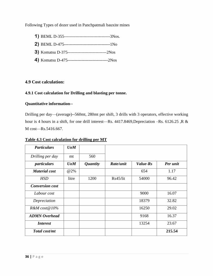
4.9 Cost calculation:
4.9.1 Cost calculation for Drilling and blasting per tonne.
Quantitative information--
Drilling per day—(average)--560mt, 280mt per shift, 3 drills with 3 operators, effective working
hour is 4 hours in a shift, for one drill interest—Rs. 4417.8469,Depreciation –Rs. 6126.25 ,R &
M cost—Rs.5416.667.
Table 4.3 Cost calculation for drilling per MT
Particulars UoM
Drilling per day mt 560
particulars UoM Quantity Rate/unit Value-Rs Per unit
Material cost @2% 654 1.17
HSD litre 1200 Rs45/lit 54000 96.42
Conversion cost
Labour cost 9000 16.07
Depreciation 18379 32.82
R&M cost@10% 16250 29.02
ADMN Overhead 9168 16.37
Interest 13254 23.67
Total cost/mt 215.54

37 | P a g e
Table 4.4 Cost of blasting per T (tonne) with gel explosive
Explosive consumption in one hole------114 kg
Drilling cost for one hole -------------------Rs 1725
Quantity generated --------------------------200
Drilling cost per MT---------------------------8.65
Total cost Drilling & blasting per MT-----33.90+8.65= Rs 42.55 per T
Particulars UoM Quantity Rate/unit Value
(Rs)
Per
unit(Rs)
Material generated Mt 560
T 1200
Material cost
Explosive kg 9000 32 288000 24
HSD for explosive
Van
litre 60 45 2700 0.25
Conversion cost
Labor cost 9000 0.75
Depreciation 4241 0.35
R&M @10% 3750 0.32
Admn OH@10% 25409 2.12
Interest 3059 5.46
Total cost 33.90

38 | P a g e
Shovel is used to excavate and load the blasted material onto dumpers. So the shovel operation
and maintenance costs = Rs. 12.42 per T.
Final cost = Rs( 42.55 + 12.42) = Rs. 54.97 per T ………………………..(1)
4.9.2 Cost calculation for ripper dozer per T (tonne)
Material generated-7200T
Executive working hours in a day--8
Two dozers operating in one shift
Diesel consumption-2000lit,
Labor cost Rs -6000 per day

39 | P a g e
Table 4.5 Ripping cost per T (tonne)
In order to load the material loader is required.
So the owning and operating cost of loader = Rs. 14.92 per T.
Therefore total cost of ripping and dozing = Rs 51.423 per T …………………….(2)
Particulars unit quantity
Material generated T 7200
Particulars UoM Quantity Rate/unit value Per unit
A) Material cost
consumbles@2% of R&M 6545 .91
HSD Litre 2000 Rs 45/lit 90000 12.5
B) Conversion cost
Laborers cost 6000 .833
Depreciation 61263 8.51
Repair& maintenance cost @10%
residual cost
32725 4.55
Admn.overhead@10% 22053 3.06
Interest on capital 44178 6.14
Total cost/per MT 36.503

40 | P a g e
4.10 Dozing operation
Different tests and cost calculation for ripping & dozing in both laterite and bauxite was done
then after techno- economic analysis carried out for selecting the appropriate method for ripping
was found. Considering ripping:-
For removal of over burden
The thickness of overburden is very less about 3mts ripping & dozing appeared to be the right
choice compared to drilling blasting due to following reasons
Drilling productivity in over burden is less due to shifting the machine for each hole for
3mts drilling. Experience has showed that nearly 20% time is wasted for shifting
Due to Low thickness powder factor in blasting is high in overburden
Pile formed after blasting is not suitable for handling properly by wheel loaders
Low moisture give rise to huge amount of silica rich dust which creates health hazards
Thickness of laterite is not uniform so by blasting operation totally removal laterite is not
possible without ripping & dozing
Removal of over burden is carried out by two method blasting as well as ripping but in loose
area where ripping is easily possible ripper dozer is deployed but for hard weathered lateritic
over burden blasting is the best option till now. Highly sloping areas where drilling is not
possible then ripper dozer of higher HP such as Komatsu 475-A is deployed. Cross ripping
practices advisably where ripping is only done not dozing for loosen the in situ
Bauxite excavation
Average thickness of the bauxite deposit is 14mts but varies from 4mts to 40mts. During the test
and observation it is found that heterogeneous bauxite formations occurring over 30% of the
initial of mining area where iron percentage varies widely across the bauxite profile where
drilling blasting is necessary but after that deposit is very weak so ripping is economical.
Various ripping techniques which is employed in the mines as follow
Close spaced ripping is employed where the mineral deposit very hard massive and
ferruginous to avoid big boulders due to degree of fracture

41 | P a g e
Cross ripping with dozing involves ripping an area with series of longitudinal passes and
then covering the same area while ripping in a transverse direction then dozing the area to
make pile this is done when extremely hard surfaces
Only Cross ripping is done where there is no requirement of dozing the material to make
pile for loading by wheel loader .it is only possible in very loose deposit.
4.11 Drawbacks of ripper dozer mining
1. Initial capital cost is higher
2. Maintenance team be bigger .In some case without spare parts dozer is kept out of
production months and more
3. Highly experienced skilled operator is prime necessary for operation so it takes long time
to make a dozer operator.
4. As operators have different skills & ideas so to maintain bench height and floor level
close supervision is necessary
5. Output very low in hard weathered laterite & ferruginous bauxite area
6. Output of dozer to the demand of production is very slow in mines
4.12 Conclusion:
Experience gained in production ripping at NALCO’s bauxite mines has conclusively
established ripping as an economically viable alternative to drilling and blasting and can be
safely resorted to where ever the rock characteristics are favorable and the suitable equipment
available within the country, production by ripping is gaining wider acceptance the world over
mainly due to the techno- economic considerations due to need lesser manpower capital
investment and uninterrupted work cycle this alternative for rock breaking is become popular
and economical.

42 | P a g e
Chapter 05
FIELD STUDY 2: TALABIRA- 1 COAL MINE, OCP, HINDALCO
5.1 Introduction:
The interest to begin coal mining under safest environment condition lead to the birth of
Talabira-1 mining operation- the first blast free coal mine in India and fist captive coal minng in
Odisha through ripper dozer and surface miner. Talabira-1 mine is situated in Sambalpur District
of Odisha. It is operated by HINDALCO. The excavated coal goes to Hirakud for captive power
generation. Mining operation is accomplished by Ripper dozer and continuos surface miner. No
crushing unit and coal handling plant are required due to deployment of surface miner.
Overburden removal and coal winning is directly handled by HINDALCO whereas loading and
transportation of overburden and coal has been handled by the contractor AVIAN OVERSEAS
Pvt. Ltd. Continuous surface miner produces coals of desired size below 150mm suitable for
using in the power plant and improves quality by selective removing the dirt band. This is
selective mining. Then the coal is transported to the destination by tippers.
5.2 Geo-mining condition:
Talabira-1 constitutes the south eastern end of Ib valley coalfield. The area allocated is 2.60
sq.km and HINDALCO lease area is 1.70 sq.km the remaining belongs to the forest department
and to the department of water resources. The mine is located near to the water reservoir of
Hirakud dam. The south eastern tongue of the coalfield is affected by three major faults ( N-S,
NW-SE, NE-SW) in which the NE-SW fault separate block from the Rampur Colliery. The rock
exposures of the Talabira-1 belong to Karharbari and Barakar formations. The three correlated
splits of Ib seam represent the Karharbari formation. The Barakar formation on the other hand,
contains five correlatable horizons of top and four splits of Rampur bottom seam. The Rampur
top seam is the youngest and the thickest seam.

43 | P a g e
Table 5.1 Geo-mining condition of Talabira-1 block (HINDALCO, 2011)
Name
of the
seam
Range of
depth
Parting
in meters
Thickness
in meters
Direction
of dip
Rate of
dip
Nature of
overburden
Rampur
top
8-54 NW-SE 5o to 10
o Top soil/
boulder clay
Rampur
bottom-
III
6-60 2-5.32 0.44-2.76 NW-SE 5o to 10
o Sandstone &
shale
Rampur
bottom-
II
6-66 071-6.15 0.44-3.01 NW-SE 5o to 10
o Sandstone &
shale
Rampur
bottom-I
6-74 0.3-3.42 0.24-5.57 NW-SE 5o to 10
o Sandstone &
shale
IB-III 18.37-
82.71
2.34 0.4-3.83 NW-SE 5o to 10
o Sandstone &
shale
IB-II 32-92.00 2.66 0.14-2.0 NW-SE 5
o to 10
o Sandstone &
shale
IB-I 36-08 0.25-2.54 NW-SE 5
o to 10
o Sandstone &
shale
44 | P a g e
5.3 Salient features of Talabira-1 OCP:
Mining lease area : 170.305 Ha
Coal bearing area : 89 Ha
Active mining area : 55 Ha
Recoverable coal reserve : 23.50 MT (million tonnes)
Grade of coal : G & F
Workable seams : 7 no.s
Use of coal : Captive power
Avg. stripping ratio : 1.09 m3/tonne
Dip of the seam : 5o-10
o
Output per manshift : 31.56 tonne
Thickness range of seams : 0.7m to 44.69m
Maximum overburden on top seam : 23m
Maximum depth to be mined : 90m
Average stripping ratio : 1.25
Cost of coal : Rs.350 per tonne.
Gross calorific value : 3250-3600 kcal. (F-G)
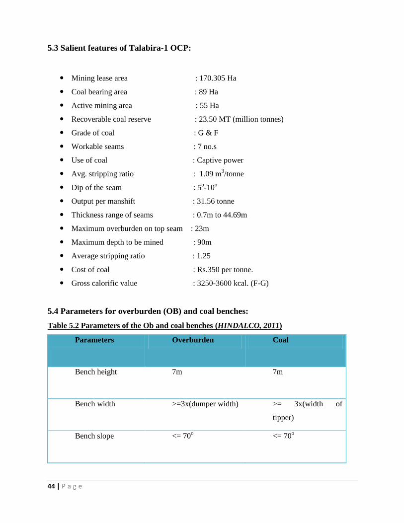
5.4 Parameters for overburden (OB) and coal benches:
Table 5.2 Parameters of the Ob and coal benches (HINDALCO, 2011)
Parameters Overburden Coal
Bench height 7m 7m
Bench width >=3x(dumper width) >= 3x(width of
tipper)
Bench slope <= 70o <= 70
o

45 | P a g e
5.5 Selection and use of Ripper dozer in Talabira-1:
Based on the seismic velocity analysis and productivity of ripper types of ripper are selected.
Also Talabira-1 is located near water reservoir of Hirakud dam. So it was dangerous to practice
drilling and blasting practices near to it. Therefore as directed by DGMS, blast free mining
method was adopted for the excavation. Ripper dozers are used to remove the overburden and
continuous surface miner is used to excavate the coal. Loaders are used to load the OB and coal
to dumpers and tippers.
HINDALCO has deployed two rippers of KOMASU D-475A for OB removal (year of
commencement – July 2003).
Feature of D-475A ripper used in Talabira-1:
Number- 2
Power:- 860 HP ( Komatsu D-475A)
Used mainly for overburden and shale (hard rock)
Cost:- Rs 4.5 crores.
Operating Cost:- Rs 20 per te (approx)
Oil consumption per hour = 120 lt
The specification of the ripper D-475A has been already mentioned in the section 4.8.

46 | P a g e
5.6 Cost Calculation:
5.6.1 Ripping cost calculation per tonne (T) of OB generated.
Table 5.3 Ripping cost per tonne of OB
Considering loader for loading the OB onto the dumpers.
Owning and operating costs of loader = Rs.14.92
Total cost of ripping = Rs.49.483 per T …………………..(3)
Particulars unit quantity
Material generated T 7800
Particulars UoM Quantity Rate/unit value Per
unit
A) Material cost
consumbles@2% of R&M 6500 .833
HSD Litre 2160 Rs 45/lit 97200 12.46
B) Conversion cost
Laborers cost 6000 .769
Depreciation 61260 7.854
Repair& maintenance cost
@10% residual cost
32500 4.167
Admn.overhead@10% 22000 2.82
Interest on capital 44178 5.66
Total cost per MT 34.563
47 | P a g e
5.6.2 Drilling and blasting cost per tonne of OB produced.
Drilling cost per meter = Rs.215.54
Hole diameter = 150mm
Hole depth = 7.8m
Drilling cost per hole = Rs.1681
Material generated = 344 T
Drilling cost per T = Rs. 4.88
Blasting operating cost = Rs.38.63 per T
Labor cost = Rs. 0.75 per T
Depreciation cost = Rs.0.35 per T
Repair and maintenance cost = Rs. 0.32 per T
Administration overhead cost = Rs.2.12 perT
Interest = Rs.5.46
Total blasting cost = Rs.47.63 per T
Shovel owning and operating cost = Rs. 12.42 per T.
Total cost incurred in drilling and blasting process = Rs 64.94 per T …………..(4)
5.7 Conclusion:
It is obvious ripping and dozing is economical but this is constrained by various factors.
Also due to location this method was adopted. Talabira 1 mine is located 50 mts away from
the Hirakud water reservoir. So it demanded a blast free mining.
For very hard strata ripping becomes expensive. So it can be associated by drilling and
blasting.

48 | P a g e
Chapter 06
RECENT DEVELOPMENTS IN THE FIELD OF RIPPER
DOZER.
1. Remote operation of ripper and dozer: ( Remote control technologies Pv.t Ltd,
Australia)
Remote Control Technologies is a world leader in remote control systems for dozer applications
and the first one to design systems for Caterpillar D5N, D8T, D9H, D10, D10N, D10R, D11N,
D11R Series 1,2,3, KOMATSU D475, D572-A2, D575A, D575A-3 & D275AX. RCT is the first
one to install remote control for a dozer CAT D11Nin PNG in 1989. In 2006 RCT was the first
in the world to remote control a CAT D8T dozer.
Following are the advantages of remote control operation:
Prevents repetitive stress injuries.
Maximization of machine utilization.
Greater overall operator vision.
Improved ergonomic working condition for operator.
Less idle time between production cycle.
More control of critical machine tolerances.
Hazardous machine tasks can be accomplished safely.
Fig.6.1 Dozer being remotely controlled.
49 | P a g e
2. Mine APS Dozer (www.apsmining.com)
MineAPS Dozer is a GPS+GLONASS machine guidance solution for dozers, enabling faster,
safer and more productive operation. High precision GPS+GLONASS guidance allows accurate
dozing to plan without the need for rechecking or pegging.
Features:
Accurately report machine position in 3D relative to digital design.
Open systems technologies includes MS Windows, SQl, XML, NMEA, Sharepoit
services.
Compact and flexible GPS+GLONASS receivers to balance investment and application.
Easy to use touch screen operator interface.
Operator can choose to work to design surface or offsets.
Support multiple user selectable surfaces in asingle file.
Onboard system diagnostics.
Fixed hazard and mobile equipment proximity warnings.
Optional ripper sensor.
Optional blade guidance sensor.
Open communications interface compatible with 3G cellular, 802.11x, mesh and other
communication systems.
Off board and onboard producitn reporting options by machine, area, group or opretor
including: volumes, push distances, cycles, rehandle, idle vs push vs ripping, delays,
export DTM of ‘as built’ surface.
Benefits of the system:
Selective mining is possible leading to improved grades.
Improved safety through fixed hazard and proximity warnings.
Improved efficiency and reduced errors.
Achieves results faster with fewer passes.
Reduce rework caused by over or under cutting or filling.
Significantly reduce dependence on survey and grade checking.
Machine based production reporting removes errors and improves timeless and accuracy
of management information.

50 | P a g e
Chapter 07
CONCLUSION
Recent developments in the ripper capabilities have made ripping a viable operation than drilling
and blasting. Although blasting can be associated with ripping in some cases, but different
studies like initial investment, operating cost, volume produced and cost incurred studies should
be done. Now a day in this eco-conscious world there is high need to conserve the environment.
Recent scenario of mining industry has to follow lot of laws & regulations of the government and
public welfare as well as political parties to run the mines. To save environment, life of wild
animal with poor villagers’ welfare will be the basic need to fulfill for smooth run of mines. Air
pollution, dust, fly rock, ground vibrations from drilling and blasting and handling explosive is
very difficult to manage for this time being. There is a high need of blast free mining. Recent
studies show that ripping is now possible for iron ore production.
In future there will be further development to apply ripping in majority surface mines and hence
will start a revolution of blast free mining.

51 | P a g e
REFERENCES
i. Amin Mohd For Mohd ; Huei Chan Sook ; Zuhairi Abd. Hamid; Mohd Khairolden
Ghani. “Rippability assessment of rock based on specific energy and production rate”, 2nd
construction industry research achievement international conference (CIRAIC2009). Pp-
3-5.
ii. Panda P.K ; Misra S.K . “ Ripping an aid to primary mining system a NALCO
experience” ,3rd
national conference on surface mining , 1989.
iii. Samal Subhrakanta ; Dash Ashish ; Murthy V.M.S.R ; Mohanty P.R. “ Ripping –an
excavation technique of future promise” , ISM Dhanbad.
iv. Basarir H. ; Karpuz C. ; Tutluoglu L. (2007). “ A fuzzy logic based rippability
classification system”. Template journal.
v. Basarir H. ; Karpuz C. ; Tutluoglu L. (2008). “ Specific energy based rippability
classification system for coal measure rock” , Journal of terramechanics.
vi. Prof.Mishra G.B, “Surface mining”, Bhubaneswar; Geominetech publications, first
edition, 2007, chapter 8-”excavation and loading”, page- 405-406.
vii. www.rct.net.au ; Remote control solutions for dozer applications., Remote control
Technologies Pvt.Ltd.,Kewdale western Australia.
viii. http://www.civil.utm.my/staff/file/116/file/Rippability%20Assessment%20of%20Rock%
20Based%20on%20Specific%20Energy%20&%20Production%20Rate.pdf
ix. http://www.saimm.co.za/Journal/v107n12p817.pdf
x. http://www.civil.utm.my/staff/file/116/file/Rippability%20Assessment%20of%20Quartzi
te%20in%20Kenny%20Hill%20Formation%5B1%5D.pdf

52 | P a g e
xi. Overburden Side Casting by Blasting-Operating large Opencast Coal Mines in a Cost
Effective Way",Partha das sharma
xii. Ramulu M.; Choudhury P.B.; Sangode A.G. and Soni A.K., 2012 “Rippability
assessment by refraction seismic survey at an iron ore mine in Karnataka” ,Mining
engineers Journal, volume 13, No.10, PP-20-27.
xiii. Komatsu company Handbook edition 30, 2010,pp-IC-14.
xiv. Xia,J., Miller R.D., and Park C.B.,1999, “Estimation of Near surface shear wave velocity
by inversion of Rayleigh wave”: Geophysics, pp 64,691-700.
xv. HINDALCO Industries limited, “Annual Mines Safety Fortnight”, 2011-12.
xvi. Atkinson, T.,1970, “Ground Penetration by ripping in open pit mining”, Mining
magazine, vol.122, pp 458-468.
xvii. Caterpillar Tractor Company, October 9182, Caterpillar performance Handbook, 13th
edition, section 1-10, caterpillar tractor Company, Peoria,IL.
xviii. Fiona MacGregor,PhD, thesis summary-“The Rippability of Rock”, pp-1, 6-8.
xix. University of Arizona , Mining and geological Engineering, “Rock Excavation”, MnE
415-515 : course notes- spring 2006, pp- 235-248.
xx. NALCO Ltd. field study.