Application of Pressure Control Type Quasi- Servo Valve … · Application of Pressure Control Type...
4
Application of Pressure Control Type Quasi- Servo Valve to Force Control System Y. Moriwake, S. Dohta, T. Akagi, and S. Shimooka Department of Intelligent Mechanical Engineering, Okayama University of Science , Okayama, Japan Email: [email protected], [email protected], [email protected], [email protected] Abstract—Today, the aged people are rapidly increasing and the number of children is decreasing in Japan. This social problem causes the demand of the care and welfare equipment to support a nursing and a self-reliance for the senior. For example, a power assist device for reducing the burden of the user has been researched and developed. The purpose of this study is to develop a small and light-weight pneumatic control valve and to apply it to the care and welfare equipment. In our previous study, the small-sized quasi-servo valve using two inexpensive on/off valves was developed and tested. The pressure control type quasi-servo valve was also proposed and tested by using the quasi-servo valve, a pressure sensor and an embedded controller. In this paper, the pressure control type quasi-servo valve is applied to a force control of the pneumatic cylinder, and its control performance is investigated. Index Terms—quasi-servo valve, pneumatic cylinder, force control I. INTRODUCTION Today, the care and welfare pneumatic devices to support a nursing care and a self-reliance of the senior and the disabled are actively researched and developed by many researchers [1], [2]. These wearable devices require many control valves for multi degrees of freedom and precise control performance of the wearable actuator. However, by increasing the degree of freedom, the total weight load of the wearable devices increases too. Therefore, we aim to develop a small-sized, light-weight and low-cost quasi-servo valve using on/off valves to decrease the burden of the user instead of expensive and bulky conventional electro-pneumatic servo valves. In our previous study [3], an inexpensive pressure control type quasi-servo valve using a low-cost embedded controller and a pressure transducer was proposed and tested. In addition, the compensation for decrease of output flow rate was proposed to improve the pressure control performance of the valve. An analytical model of the pressure control type quasi-servo valve including the embedded controller was also proposed. The control performance of the valve using P and PD controller was investigated theoretically [4]. We also investigated the optimal control parameter of the PD controller by means of simulation. It is easier to realize the force control when the pressure control type valve is used. In this paper, as Manuscript received January 1, 2015; revised June 12, 2015. an application of the pressure control type quasi-servo valve, the force control system is built and tested by using a pneumatic cylinder. The force control system consists of the pressure control type valve, a pneumatic cylinder and an electric linear actuator. II. CONSTRUCTION AND OPERATING PRINCIPLE OF QUASI-SERVO VALVE Fig. 1 shows the schematic diagram of the quasi-servo valve developed before [5]. The valve consists of two on/off type control valves (Koganei Co. Ltd., G010HE-1) whose both output ports are connected to each other. One valve is used as a switching valve to exhaust or supply, and the other is used as a PWM control valve that can adjust output flow rate like a variable fluid resistance. The valve connected with the actuator is a two-port valve without exhaust port. The other is a three-port valve that can change the direction of fluid flow from the supply port to the output port or the fluid flow from the output port to the exhaust port. The two-port valve is driven by pulse width modulation method in order to adjust the valve opening per time. The size of the on/off valve is 33×19.6×10 mm, and the mass is only 15 g. The maximum output flow rate is 38 liter/min at 500 kPa. Figure 1. Schematic diagram of quasi-servo valve. III. PRESSURE CONTROL TYPE QUASI-SERVO VALVE A. Construction Fig. 2 shows the schematic diagram of the pressure control type quasi-servo valve. The valve system consists of the above quasi-servo valve, a pressure sensor (Matsushita Electronics Co. Ltd., ADP5160) and an embedded controller (Renesas Co. Ltd. R8C12M). The pressure control is done as follows. The embedded controller gets the sensor output voltage and the reference voltage through an inner 10 bit A/D converter. The manipulated value for the PWM valve, duty ratio, is Journal of Automation and Control Engineering Vol. 4, No. 3, June 2016 ©2016 Journal of Automation and Control Engineering 209 doi: 10.18178/joace.4.3.209-212
Transcript of Application of Pressure Control Type Quasi- Servo Valve … · Application of Pressure Control Type...
Application of Pressure Control Type Quasi-
Servo Valve to Force Control System
Y. Moriwake, S. Dohta, T. Akagi, and S. Shimooka Department of Intelligent Mechanical Engineering, Okayama University of Science , Okayama, Japan
Email: [email protected], [email protected], [email protected], [email protected]
Abstract—Today, the aged people are rapidly increasing and
the number of children is decreasing in Japan. This social
problem causes the demand of the care and welfare
equipment to support a nursing and a self-reliance for the
senior. For example, a power assist device for reducing the
burden of the user has been researched and developed. The
purpose of this study is to develop a small and light-weight
pneumatic control valve and to apply it to the care and
welfare equipment. In our previous study, the small-sized
quasi-servo valve using two inexpensive on/off valves was
developed and tested. The pressure control type quasi-servo
valve was also proposed and tested by using the quasi-servo
valve, a pressure sensor and an embedded controller. In this
paper, the pressure control type quasi-servo valve is applied
to a force control of the pneumatic cylinder, and its control
performance is investigated.
Index Terms—quasi-servo valve, pneumatic cylinder, force
control
I. INTRODUCTION
Today, the care and welfare pneumatic devices to
support a nursing care and a self-reliance of the senior
and the disabled are actively researched and developed by
many researchers [1], [2]. These wearable devices require
many control valves for multi degrees of freedom and
precise control performance of the wearable actuator.
However, by increasing the degree of freedom, the total
weight load of the wearable devices increases too.
Therefore, we aim to develop a small-sized, light-weight
and low-cost quasi-servo valve using on/off valves to
decrease the burden of the user instead of expensive and
bulky conventional electro-pneumatic servo valves. In
our previous study [3], an inexpensive pressure control
type quasi-servo valve using a low-cost embedded
controller and a pressure transducer was proposed and
tested. In addition, the compensation for decrease of
output flow rate was proposed to improve the pressure
control performance of the valve. An analytical model of
the pressure control type quasi-servo valve including the
embedded controller was also proposed. The control
performance of the valve using P and PD controller was
investigated theoretically [4]. We also investigated the
optimal control parameter of the PD controller by means
of simulation. It is easier to realize the force control when
the pressure control type valve is used. In this paper, as
Manuscript received January 1, 2015; revised June 12, 2015.
an application of the pressure control type quasi-servo
valve, the force control system is built and tested by using
a pneumatic cylinder. The force control system consists
of the pressure control type valve, a pneumatic cylinder
and an electric linear actuator.
II. CONSTRUCTION AND OPERATING PRINCIPLE OF
QUASI-SERVO VALVE
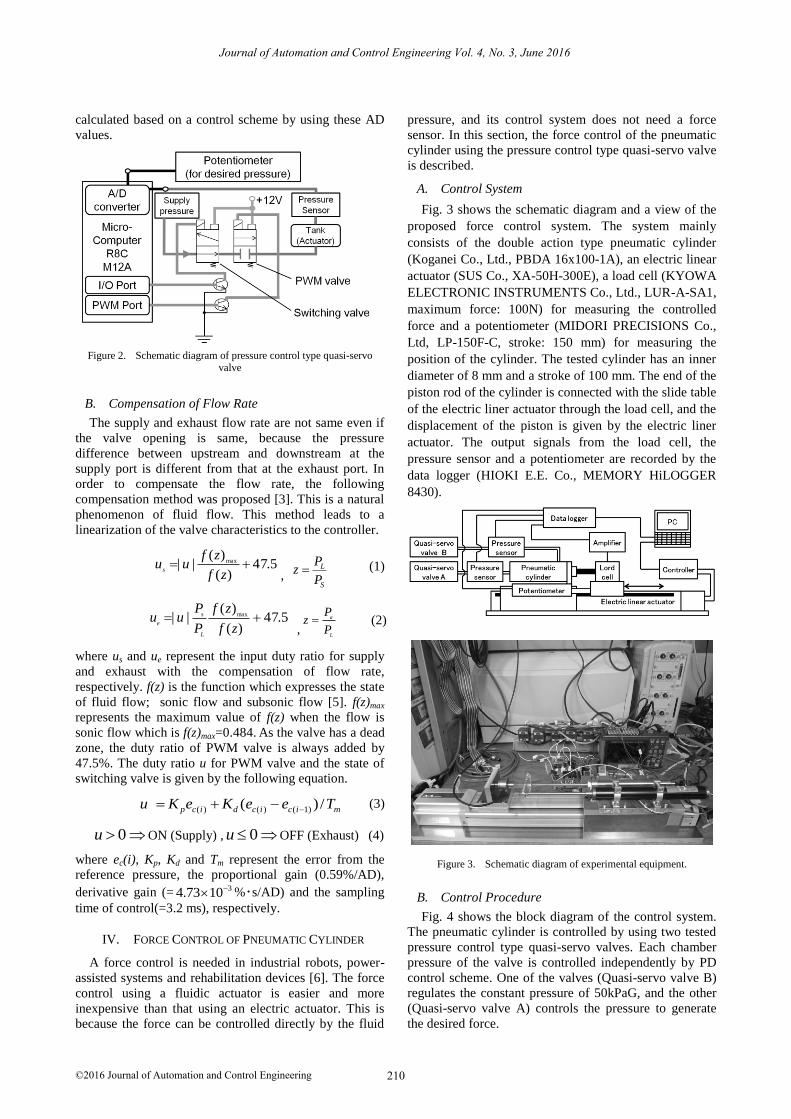
Fig. 1 shows the schematic diagram of the quasi-servo
valve developed before [5]. The valve consists of two
on/off type control valves (Koganei Co. Ltd., G010HE-1)
whose both output ports are connected to each other. One
valve is used as a switching valve to exhaust or supply,
and the other is used as a PWM control valve that can
adjust output flow rate like a variable fluid resistance.
The valve connected with the actuator is a two-port valve
without exhaust port. The other is a three-port valve that
can change the direction of fluid flow from the supply
port to the output port or the fluid flow from the output
port to the exhaust port. The two-port valve is driven by
pulse width modulation method in order to adjust the
valve opening per time. The size of the on/off valve is
33×19.6×10 mm, and the mass is only 15 g. The
maximum output flow rate is 38 liter/min at 500 kPa.
Figure 1.
Schematic diagram of quasi-servo valve.
III. PRESSURE CONTROL TYPE QUASI-SERVO VALVE
A. Construction
Fig. 2 shows the schematic diagram of the pressure
control type quasi-servo valve. The valve system consists
of the above quasi-servo valve, a pressure sensor
(Matsushita Electronics Co. Ltd., ADP5160) and an
embedded controller (Renesas Co. Ltd. R8C12M). The
pressure control is done as follows. The embedded
controller gets the sensor output voltage and the reference
voltage through an inner 10 bit A/D converter. The
manipulated value for the PWM valve, duty ratio, is
Journal of Automation and Control Engineering Vol. 4, No. 3, June 2016
©2016 Journal of Automation and Control Engineering 209doi: 10.18178/joace.4.3.209-212
calculated based on a control scheme by using these AD
values.
Figure 2. Schematic diagram of pressure control type quasi-servo valve
B. Compensation of Flow Rate
The supply and exhaust flow rate are not same even if
the valve opening is same, because the pressure
difference between upstream and downstream at the
supply port is different from that at the exhaust port. In
order to compensate the flow rate, the following
compensation method was proposed [3]. This is a natural
phenomenon of fluid flow. This method leads to a
linearization of the valve characteristics to the controller.
5.47)(
)(|| max
zf
zfuu
s
, S
L
P
Pz (1)
5.47)(
)(|| max
zf
zf
P
Puu
L
s
e ,
L
a
P
Pz (2)
where us and ue represent the input duty ratio for supply
and exhaust with the compensation of flow rate,
respectively. f(z) is the function which expresses the state
of fluid flow; sonic flow and subsonic flow [5]. f(z)max
represents the maximum value of f(z) when the flow is
sonic flow which is f(z)max=0.484. As the valve has a dead
zone, the duty ratio of PWM valve is always added by
47.5%. The duty ratio u for PWM valve and the state of
switching valve is given by the following equation.
micicdicp TeeKeKu /)( )1()()(
(3)
0u ON (Supply) , 0u OFF (Exhaust) (4)
where ec(i), Kp, Kd and Tm represent the error from the
reference pressure, the proportional gain (0.59%/AD),
derivative gain (= 31073.4 %・s/AD) and the sampling
time of control(=3.2 ms), respectively.
IV. FORCE CONTROL OF PNEUMATIC CYLINDER
A force control is needed in industrial robots, power-
assisted systems and rehabilitation devices [6]. The force
control using a fluidic actuator is easier and more
inexpensive than that using an electric actuator. This is
because the force can be controlled directly by the fluid
pressure, and its control system does not need a force
sensor. In this section, the force control of the pneumatic
cylinder using the pressure control type quasi-servo valve
is described.
A. Control System
Fig. 3 shows the schematic diagram and a view of the
proposed force control system. The system mainly
consists of the double action type pneumatic cylinder
(Koganei Co., Ltd., PBDA 16x100-1A), an electric linear
actuator (SUS Co., XA-50H-300E), a load cell (KYOWA
ELECTRONIC INSTRUMENTS Co., Ltd., LUR-A-SA1,
maximum force: 100N) for measuring the controlled
force and a potentiometer (MIDORI PRECISIONS Co.,
Ltd, LP-150F-C, stroke: 150 mm) for measuring the
position of the cylinder. The tested cylinder has an inner
diameter of 8 mm and a stroke of 100 mm. The end of the
piston rod of the cylinder is connected with the slide table
of the electric liner actuator through the load cell, and the
displacement of the piston is given by the electric liner
actuator. The output signals from the load cell, the
pressure sensor and a potentiometer are recorded by the
data logger (HIOKI E.E. Co., MEMORY HiLOGGER
8430).
Figure 3. Schematic diagram of experimental equipment.
B. Control Procedure
Fig. 4 shows the block diagram of the control system.
The pneumatic cylinder is controlled by using two tested
pressure control type quasi-servo valves. Each chamber
pressure of the valve is controlled independently by PD
control scheme. One of the valves (Quasi-servo valve B) regulates the constant pressure of 50kPaG, and the other (Quasi-servo valve A) controls the pressure to generate
the desired force.
Journal of Automation and Control Engineering Vol. 4, No. 3, June 2016
©2016 Journal of Automation and Control Engineering 210

Figure 4. Block diagram of tested system.
C. Control Results and Discussion
Fig. 5 shows the control result of the cylinder force.
The reference force is 5N. In the figure, the solid and
dotted lines show the measured force and displacement of
piston, respectively. The displacement of triangle wave
with an offset of 40 mm and an amplitude of 20 mm was
applied to the cylinder. The piston speed is plus or minus
16 mm/s. From the figure, it is observed that there is a big
difference between reference force and measured force.
The constant force opposite to the moving direction of the
slide table can be found. This is caused by Coulomb
friction between the piston and the cylinder. Therefore,
the friction characteristic of the cylinder was investigated
by the experiment.
Figure 5. Control result (without friction compensation).
Fig. 6 shows the relation between velocity of the piston
and frictional force. The experiment was carried out three
times under the constant velocity of the slide table, and
the force was measured at the certain position. From the
experimental results, the following relation is obtained.
)sgn(21.38.13 ccc VVF (5)
where Fc
[N] and Vc
[m/s] represent
the frictional force
and the velocity of the piston, respectively. From this
equation, the coulomb
friction of 3.21 N and the
coefficient of viscous resistance
of 13.8 N/(m・ s) are
obtained. In the following experiment, based on this
result, the force control with friction compensation was
tried.
Figure 6. Friction characteristics.
Fig. 7 shows the force control result using tested valve
with friction compensation. The compensation method is
as follows. The sign of piston velocity is detected, and the
pressure corresponding to the frictional force of 3.21 N is
added or subtracted based on the sign. This control
procedure is also shown in the block diagram in Fig. 4.
From Fig. 7, it is found that there still exists an error of
1.8 N between reference and measured force. It is also
observed that there is a sudden change of measured force
when the piston displacement is the maximum and the
moving direction is changed. At this position, the
cylinder is extended largely and the chamber volume
becomes maximum. It is considered that the sudden
change is caused by the time delay of the pressure
response due to the larger chamber volume. We think that
these problems can be solved by improving the control
scheme.
Figure 7. Control result (with friction compensation).
V.
CONCLUSIONS
The purpose of this study is to develop a small and
light-weight pneumatic control valve and to apply it to
Journal of Automation and Control Engineering Vol. 4, No. 3, June 2016
©2016 Journal of Automation and Control Engineering 211

the care and welfare equipments. This study can be
summarized as follows.
The small-sized quasi-servo valve which consists of
two inexpensive on/off valve is explained. The pressure
control type quasi-servo valve is built by the quasi-servo
valve, a pressure sensor and an embedded controller. The
force control using the pressure control type quasi-servo
valve is easier and more inexpensive than others.
Therefore, as an application of the tested pressure control
type quasi-servo valve, the force control system of the
cylinder is built and tested. The force control system
consists of a pneumatic cylinder, an electric linear
actuator, a load cell and a potentiometer. As a result, a
large error between reference and measured force was
observed. This is because of Coulomb friction in the
cylinder. Then, the friction characteristics were
investigated and the control performance was improved
by compensating the friction.
ACKNOWLEDGMENT
Finally, we express our thanks that this work was
supported in part by MEXT in Japan through a QOL
Innovative Research Program (2012).
REFERENCES
[1] T. Noritsugu, M. Takaiwa, and D. Sasaki, “Realization of all 7
motions for the upper limb by a muscle suit,” Journal of Robotics and Mechatronics, vol. 21, no. 5, pp. 607-613, 2009.
[2] H. Kobayashi, T. Shiba, and Y. Ishida, “Development of power assist wear using pneumatic rubber artificial muscles,” Journal of
Robotics and Mechatronics, vol. 16, no. 5, pp. 504-512, 2004.
[3] Y. Moriwake, T. Akagi, S. Dohta, and F. Zhao, “Development of low-cost pressure control type quasi-servo valve using embedded
controller,” Journal of Procedia Engineering, vol. 41, pp. 493-500, 2012.
[4] Y. Moriwake, T. Akagi, S. Dohta, and F. Zhao, “Improvement of
pressure control type quasi-servo valve and on/off valves using embedded controller,” in Proc. 2013 IEEE/ASME International
Conf. on Advanced Intelligent Mechatronics, 2013, pp. 882-887. [5] F. Zhao, S. Dohta, and T. Akagi, “ Development and analysis of
small-sized quasi-servo valve for flexible bending actuator,”
Transactions of the Japan Society of Mechanical Engineers, Series C, vol. 76, no. 772, pp. 3665–3671, 2010.
[6] S. Moromugi, T. Tanaka, T. Higashi, M. Q. Feng, and T. Ishimatsu, “Pneumatically driven prehension orthosis with force
control function,” Journal of Robotics and Mechatronics, vol. 25,
no. 6, pp. 973-982, 2013.
Yoshinori Moriwake received the B.S. degree in Engineering from Okayama
University of Science, Japan in 2012. And he
received the M.S. degree in Engineering from Okayama University of Science in 2014. He
is currently a Ph.D student in Graduate School of Engineering, Okayama University
of Science. His research interests are focusing
on wearable control systems using microcomputers and wearable control devices
such as a small-sized servo valve. He is a member of The Japan Fluid Power System Society (JFPS).
University in 1990. His major in mechatronics is focusing on the
development of robotics, wearable devices for rehabilitation purpose.
Prof. Shujiro Dohta
is a current member of The Japan Society of
Mechanical Engineers (JSME), The Society of Instrument and Control
Engineers (SICE), The Robotics Society of Japan (RSJ), and The Japan Fluid Power System Society (JFPS)..
Tetsuya Akagi
is currently a
professor of Department of Intelligent Mechanical
Engineering, Okayama University of Science, Japan.
He received his doctor degree in
Engineering from Okayama University of
Science in 1998. He started
at
Tsuyama National College of Technology, Japan as a
research associate on 1998. Then, he joined Okayama University of Science as a lecturer
starting from 2005. His research interests
include mechatronics and robotics; especially wearable control systems using microcomputers and wearable control devices such as flexible
pneumatic actuator, soft sensor and wearable control valve.
Prof. Tetsuya Akagi is currently a member of The Japan Society of
Mechanical Engineers (JSME), The Society of Instrument and Control
Engineers (SICE), The Robotics Society of Japan (RSJ), and The Japan Fluid Power System Society (JFPS).
So Shimooka received the B.S.
degree in Engineering from Okayama University of
Science, Japan
in 2014. He is currently a master-course student in Graduate School of
Engineering, Okayama University of Science.
His research interests
are
focusing on wearable control systems using
microcomputers and wearable control devices such as an artificial muscle
with built-
in
sensor.
He
is
a member of The Japan Fluid
Power System
Society
(JFPS).
Shujiro Dohta is currently a professor of
Department of Intelligent Mechanical
Engineering, Okayama University of Science, Japan. He is also currently a Vice-president
of Okayama University of Science. He joined Okayama University of Science as a research
associate on 1974. Then, he became an
Exchange Faculty of Wright State University, U.S.A. from 1984 to 1985. He received his
doctor degree in Engineering from Kobe
Journal of Automation and Control Engineering Vol. 4, No. 3, June 2016
©2016 Journal of Automation and Control Engineering 212