APPLICATION OF FINITE ELEMENT MODEL UPDATING FOR …
19
INTERNATIONAL JOURNAL OF OPTIMIZATION IN CIVIL ENGINEERING Int. J. Optim. Civil Eng., 2018; 8(2):275-293 APPLICATION OF FINITE ELEMENT MODEL UPDATING FOR DAMAGE ASSESSMENT OF SPACE STRUCTURE USING CHARGED SYSTEM SEARCH ALGORITHM H. Safari and A. Gholizad *, † Department of Civil Engineering, University of Mohaghegh Ardabili, Ardabil, Iran ABSTRACT Damage assessment is one of the crucial topics in the operation of structures. Multiplicities of structural elements and joints are the main challenges about damage assessment of space structure. Vibration-based damage evaluation seems to be effective and useful for application in industrial conditions and the low-cost. A method is presented to detect and assess structural damages from changes in mode shapes. First, the mechanism of using two-dimensional continuous wavelet transform is applied for damage localization. Second, finite element model updating technique is utilized as an inverse optimization problem by applying the charged system search algorithm to assess the damage in each element sited in the first stage. The study indicates the potentiality of the developed code to assess the damages of space structures without concerning about the size and shape of structure. A series of numerical examples with different damage scenarios have been carried out in the double layer space structures and the results confirm the reliability and applicability of introduced method. Keywords: damage detection, 2D continuous wavelet transform, finite element model updating, space structure, charged system search algorithm. Received: 10 July 2017; Accepted: 7 September 2017 1. INTRODUCTION Damage detection using structural modal identification methods is based on the premise that damage is manifested as a loss of effective stiffness over one or more regions of the structure. These damages may endanger structure’s integrity and functionality and need to be accurately detected [1]. Vibration based Structural Health Monitoring (SHM) became an interesting research topic in structural mechanics around 30 years ago. Vibration methods are based on the fact * Corresponding author: University of Mohaghegh Ardabili, Ardabi, Iran † E-mail address: [email protected] (A. Gholizad)
Transcript of APPLICATION OF FINITE ELEMENT MODEL UPDATING FOR …

INTERNATIONAL JOURNAL OF OPTIMIZATION IN CIVIL ENGINEERING
Int. J. Optim. Civil Eng., 2018; 8(2):275-293
APPLICATION OF FINITE ELEMENT MODEL UPDATING FOR
DAMAGE ASSESSMENT OF SPACE STRUCTURE USING
CHARGED SYSTEM SEARCH ALGORITHM
H. Safari and A. Gholizad*, †
Department of Civil Engineering, University of Mohaghegh Ardabili, Ardabil, Iran
ABSTRACT
Damage assessment is one of the crucial topics in the operation of structures. Multiplicities of
structural elements and joints are the main challenges about damage assessment of space
structure. Vibration-based damage evaluation seems to be effective and useful for application
in industrial conditions and the low-cost. A method is presented to detect and assess structural
damages from changes in mode shapes. First, the mechanism of using two-dimensional
continuous wavelet transform is applied for damage localization. Second, finite element model
updating technique is utilized as an inverse optimization problem by applying the charged
system search algorithm to assess the damage in each element sited in the first stage. The
study indicates the potentiality of the developed code to assess the damages of space structures
without concerning about the size and shape of structure. A series of numerical examples with
different damage scenarios have been carried out in the double layer space structures and the
results confirm the reliability and applicability of introduced method.
Keywords: damage detection, 2D continuous wavelet transform, finite element model
updating, space structure, charged system search algorithm.
Received: 10 July 2017; Accepted: 7 September 2017
1. INTRODUCTION
Damage detection using structural modal identification methods is based on the premise that
damage is manifested as a loss of effective stiffness over one or more regions of the
structure. These damages may endanger structure’s integrity and functionality and need to
be accurately detected [1].
Vibration based Structural Health Monitoring (SHM) became an interesting research
topic in structural mechanics around 30 years ago. Vibration methods are based on the fact
*Corresponding author: University of Mohaghegh Ardabili, Ardabi, Iran †E-mail address: [email protected] (A. Gholizad)
H. Safari and A. Gholizad
276
that the reduction of stiffness due to damage affects the dynamic response of structure.
Alteration of the vibration characteristics of the structure, such as the natural frequency,
displacement, mode shapes and damping ratios are signs to observe the damage in the
structure [2].
Vibration based methods are typified by Fourier transform [3,4], wavelet transform [5,6],
time-frequency analysis [7,8], and intelligent computation [9]. Wavelet transform
background comes from the beginning of the last century [10], and its development as an
engineering signal processing analysis tool for SHM is rather new [11]. Wavelet analysis is
an efficient methodology which has found wide applications in structural health monitoring
(SHM) problems. Wavelet transform is mainly attractive because of its ability to compress
and encode information, to reduce noise, or to detect any local singular behavior of a signal.
Wavelet-based methods have been applied by researchers for detection and localization
of damages in one-dimensional structural parts (beams) [12-14] and 2D plane problems
(plate) [15-18].
An appropriate feature must be sensitive enough to damage, but rather insensitive to
environmental and operational effects; hence, selecting a suitable damage indicator feature is a
major issue in this approach. The literatures about the vibration based damage identification
methods are abundant and several damages sensitive features have been proposed in the
previous research [19-21]. Among different structural responses that can be used as measures
of structural damage, modal parameters enjoy the benefit of being independent of external
excitation [22]. If a modal analysis is performed, then wavelet analysis can be applied to mode
shapes or their derivatives to detect changes induced by damage.
Space structures, which enable the designers to cover large spans as sports stadiums,
assembly halls, exhibition centers, swimming pools, shopping centers and industrial
buildings have been widely applied by structural and architectural engineers in the recent
decades. According to the application of structure, various types of space frames like
geodesic dome, double layer grid and pyramid could be designed. In the prior methods
introduced by other researchers for damage detection of truss like structures, size of
structure, differences in geometric patterns and verity of shape were the key problems to
limit the application of these methods [1,23-25].
To reduce the computational costs and time, the mechanism of using two dimensional
continuous wavelet transform (2D- CWT) is applied by exploiting the concept of simulating
the mode shape of space structure to a 2D spatially distributed signal for damage localization
of space structure [2].
In the last few decades, techniques based on finite element model updating (FEMU) have
been widely developed for vibration-based damage detection. The basic idea is to change the
properties of the numerical model to fit the values provided by experimental data,
identifying damaged regions and the extent of damage on the structure. In other words, the
optimization algorithm seeks the optimal reduction factors of element's stiffness to achieve a
predefined performance in terms of the modal parameters defined by the experimental data
[26]. SR Shiradhonkar and M. Shrikhande [27] used the frequency-domain decomposition
and empirical transfer function estimates to identify the modal parameters. They found that a
combination of system identification techniques with sensitivity based finite element model
updating can potentially locate and quantify the damage in a moment resistant frame. YZ Fu,
et al. [28] used the inverse response sensitivity- based finite element model updating

APPLICATION OF FINITE ELEMENT MODEL UPDATING FOR DAMAGE …
277
approach with the penalty function method with Tikhonov regularization to identify local
damages of the plate in the time domain. A Majumdar, et al. [23] formulate the inverse
problem in terms of optimization and utilized a solution technique employing ant colony
optimization to detect and assess structural damages from changes in natural frequencies.
The developed code is used to assess damages of truss like structures using first few natural
frequencies. An improvement in the hybrid Pincus-Nelder-Mead optimization algorithm (P-
NMA) which enables to solve the target optimization problem of vibration-based damage
detection is proposed by [29], and the results of a beam modeled with 25 finite elements
were compared to those obtained by the P-NMA and the meta heuristic harmony search
algorithm. ZH Ding, et al. [24] used artificial bee colony algorithm with hybrid search
strategy based on an objective function established in the frequency domain for damage
detection on a truss and plate structures. SM Seyedpoor [25] proposed a two-stage method
of determining the location and extent of multiple structural damages. First, the damage is
located using the concept of modal strain energy and second; the particle swarm
optimization is utilized to determine the extent of damaged elements. The method is
assessed by a planar truss with 31 elements.
This paper presents a framework for SHM and damage assessment of space structure. In
the first stage, the mechanism of using 2D- CWT is applied for damage localization of space
structure [2]. In the second stage, finite element model updating (FEMU) technique is
utilized as an inverse optimization problem by applying the charged system search (CSS)
algorithm [30] to assess the amount of damage of each element sited in the first stage.
Numerical results show the high efficiency of the proposed method for accurately
identifying the extent of multiple structural damages.
2. THEORETICAL BACKGROUND
2.1 Two-dimensional continuous wavelet transform
Wavelet analysis provides a powerful tool to characterize the local features of a signal.
Unlike the Fourier transform, where the function used as the basis of decomposition is
always a sinusoidal wave, other basis functions can be selected for wavelet shape according
to the features of the signal.
The two-dimensional CWT (2D-CWT) is a natural extension of the one-dimensional
CWT, with the translation parameter being a vector in the plane. As in the 1D case, a 2D
wavelet is an oscillatory, real or complex-valued function 𝜓 𝑥 𝜖 𝐿2(𝑅2,𝑑2𝑥 ) satisfying the
admissibility condition on real plane 𝑥 𝜖 𝑅2, 𝐿2(𝑅2,𝑑2𝑥 ) denotes the Hilbert space of
measurable, square integrable 2D functions on the plane. If 𝜓 is regular enough as in most
cases, the admissibility condition can be expressed as:
𝜓(0 ) = 0 ⟺ 𝜓 𝑥 𝑑2𝑥 = 0𝑅2
(1)
Function 𝜓 𝑥 is called mother wavelet and usually localized in both the position and
frequency domains. The mother wavelet 𝜓 can be transformed in the plane to generate a

H. Safari and A. Gholizad
278
family of wavelet 𝜓𝑎 ,𝑏 ,𝜃 𝑥 . A transformed wavelet 𝜓𝑎 ,𝑏 ,𝜃
𝑥 under translation by a vector
𝑏 , dilation by a scaling factor 𝑎, and rotation by an angel 𝜃 can be derived as [31]:
𝜓𝑎 ,𝑏 ,𝜃 𝑥 = 𝑎−1𝜓 𝑟−𝜃
𝑥 − 𝑏
𝑎 𝑎 > 0, 𝑏 ,𝜃𝜖𝑅2 (2)
Given a 2D signal 𝑓(𝑥 )𝜖𝐿2(𝑅2,𝑑2𝑥 ), its 2D-CWT (with respect to the wavelet 𝜓)
𝑊𝑓 𝑎, 𝑏 , 𝜃 is the scalar product of 𝑓(𝑥 ) with the transformed wavelet 𝜓𝑎 ,𝑏 ,𝜃 and
considered as a function of 𝑎, 𝑏 , 𝜃 as:
Wf a, b , θ = f,ψa,b ,θ =
1
a f(x )ψ∗ r−θ
x − b
a d2x
+∞
−∞
(3)
where the 𝜓∗ denotes the complex conjugate and 𝑟−𝜃 is the 2D rotation matrix as:
r−θ = cos θ − sin θ
sin θ cos(θ) (4)
The 2D-CWT is a space scale representation of a plane and acts as a local filter with
scale and position. If the wavelet is isotropic, there is no dependence on angle in the
analysis. The Mexican hat wavelet is an example of an isotropic wavelet. Isotropic
wavelets are suitable for point wise analysis of a 2D system. If the wavelet is
anisotropic, there is a dependence on angle in the analysis, and the 2D-CWT acts a local
filter with scale, position, and angle. The morlet wavelet is an example of an anisotropic
wavelet. In the Fourier domain, this means that the spatial frequency support of the
wavelet is a convex cone with the apex at the origin. Anisotropic wavelets are suitable
for detecting directional feature.
The point wise nature of the 2D damage detection in the space structure is made the
isotropic wavelets suitable for this kind of structure. The chosen wavelet function is
isotropic Mexican hat wavelet, and the scaled is equal to 2. Wavelet computation is
performed using MATLAB code.
The denoising and filtering capability of the isotropic 2D-CWT provides us with an
important analysis tool in practice. The Mexican hat wavelet is real and isotropic. The
1D Mexican hat wavelet is the second derivative of the Gaussian function. Likewise, the
2D Mexican hat wavelet is the Laplacian of the 2D Gaussian function. It was first
proposed by EC Hildreth [32] as a differential-smooth operator for their edge contours
detection theory. Its expression in the position domain is given as follows [15]:
ψ x = 2 − x 2 exp −1
2 x 2 (5)

APPLICATION OF FINITE ELEMENT MODEL UPDATING FOR DAMAGE …
279
2.2 Charged system search algorithm
The Charged System Search (CSS) algorithm is based on the Coulomb and Gauss laws from
electrical physics and the governing laws of motion from the Newtonian mechanics. This
algorithm can be considered as a multi-agent approach, where each agent is a Charged
Particle (CP). In this section, CSS is represented briefly. The CSS algorithm can be
summarized as follows:
Level 1. Initialization
Step 1. Initialization. The initial positions of CPs are determined randomly in the search
space as:
𝑥𝑖 ,𝑗(0)
= 𝑥𝑖 ,𝑚𝑖𝑛 + 𝑟𝑎𝑛𝑑. 𝑥𝑖 ,𝑚𝑎𝑥 − 𝑥𝑖 ,𝑚𝑖𝑛 , 𝑖 = 1, 2,… ,𝑛 (6)
where 𝑥𝑖 ,𝑗(0)
determines the initial value of the ith variable for the jth CP; 𝑥𝑖 ,𝑚𝑖𝑛 and 𝑥𝑖 ,𝑚𝑎𝑥 are
the minimum and the maximum allowable values for the ith variable; rand is a random
number in the interval [0,1]; and n is the number of variables. The initial velocities of
charged particles are set to zero
𝑣𝑖 ,𝑗(0)
= 0, 𝑖 = 1, 2,… ,𝑛 (7)
The magnitude of the charge is defined considering the quality of its solution, as follows:
qi =fit i − fitworst
fitbest − fitworst i = 1,2,3… . . , N (8)
where fitbest and fitworst are the so far best and the worst fitness of all particles; fit(i)
represents the objective function value or the fitness of the agent i; and N is the total number
of CPs. The separation distance 𝑟𝑖𝑗 between two charged particles is defined as follows:
rij = 𝐗i − 𝐗j
𝐗i − 𝐗j 2 − 𝐗best + ε (9)
where 𝐗i and 𝐗j are the positions of the ith and jth CPs, 𝐗best is the position of the best
current CP, and ε is a small positive number to avoid singularities.
Step 2. CP ranking. Evaluate the values of the fitness function for the CPs, compare with
each other and sort them in an increasing order.
Step 3. CM creation. Store the number of the first CPs equal to charged memory size
(CMS) and their related values of the fitness functions in the charged memory (CM).
Level 2. Search
Step 1. Attracting force determination. Determine the probability of moving ith CP
toward the jth CP is expressed by the following probability function:
H. Safari and A. Gholizad
280
pij = 1 fit i − fitbest
fit j − fit i > 𝑟𝑎𝑛𝑑 ∨ 𝑓𝑖𝑡 j > 𝑓𝑖𝑡 i
0 otherwise
(10)
The value of the resultant electrical force acting on a CP is determined as:
𝐅j = qi qi
a3rij . i1 +
qi
rij2 . i2 pij 𝐗i − 𝐗j
i,i≠j
j = 1, 2,… . , N i1 = 1, i2 = 0 ⇔ rij < 𝑎
i1 = 0, i2 = 1 ⇔ rij ≥ a
(11)
where 𝑞𝑖 the volume charge density of the jth particle and it has a value between 0 and 1; 𝑭𝑗
is the resultant force acting on the jth CP; 𝑟𝑖𝑗 is the separation distance between two charged
particles which is defined as Eq. 12.
Step 2. Solution construction. Move each CP to the new position and find its velocity
using the following equations:
𝑿𝑗 .𝑛𝑒𝑤 = 𝑟𝑎𝑛𝑑𝑗1.𝑘𝑎 .𝑭𝑗𝑚𝑗
△ 𝑡2 + 𝑟𝑎𝑛𝑑𝑗2. 𝑘𝑣 .𝑽𝑗 .𝑜𝑙𝑑 △ 𝑡 + 𝑿𝑗 .𝑜𝑙𝑑 (12)
𝑽𝑗 .𝑛𝑒𝑤 =𝑿𝑗 .𝑛𝑒𝑤 − 𝑿𝑗 .𝑜𝑙𝑑
△ 𝑡 (13)
where 𝑘𝑎 is the acceleration coefficient; 𝑘𝑣 is the velocity coefficient to control the influence
of the previous velocity; and 𝑟𝑎𝑛𝑑𝑗1 and 𝑟𝑎𝑛𝑑𝑗2 are two random numbers uniformly
distributed in the range of (0,1). △ 𝑡 is the time step and set to unity. 𝑘𝑎 and 𝑘𝑣 are defined
as:
𝑘𝜈 = 0.5 1 − 𝑖𝑡𝑒𝑟 𝑖𝑡𝑒𝑟𝑚𝑎𝑥 𝑘𝑎 = 0.5(1 + 𝑖𝑡𝑒𝑟 𝑖𝑡𝑒𝑟𝑚𝑎𝑥 ) (14)
where iter is the actual iteration number and 𝑖𝑡𝑒𝑟𝑚𝑎𝑥 is the maximum number of iterations.
Step 3. Modification of CP position. If each CP violates from its allowable boundary, its
position is corrected as fallow:
𝑥𝑖 ,𝑗 =
𝑤. 𝑝.𝐶𝑀𝐶𝑅 ⟹ 𝑠𝑒𝑙𝑒𝑐𝑡 𝑎 𝑛𝑒𝑤 𝑣𝑎𝑙𝑢𝑒 𝑓𝑜𝑟 𝑎 𝑣𝑎𝑟𝑖𝑎𝑏𝑙𝑒 𝑓𝑟𝑜𝑚 𝐶𝑀,
⟹𝑤.𝑝. 1 − 𝑃𝐴𝑅 𝑑𝑜 𝑛𝑜𝑡𝑖𝑛𝑔, ⟹𝑤. 𝑝.𝑃𝐴𝑅 𝑐𝑜𝑜𝑠𝑒 𝑎 𝑛𝑒𝑖𝑔𝑏𝑜𝑟𝑖𝑛𝑔 𝑣𝑎𝑙𝑢𝑒,
𝑤.𝑝. 1 − 𝐶𝑀𝐶𝑅 ⟹ 𝑠𝑒𝑙𝑒𝑐𝑡 𝑎 𝑛𝑒𝑤 𝑣𝑎𝑙𝑢𝑒 𝑟𝑎𝑛𝑑𝑜𝑚𝑙𝑦,
(15)
where “w.p.” is the abbreviation for “with the probability”; 𝑥𝑖 ,𝑗 is the ith component of
the CP j; The CMCR (the Charged Memory Considering Rate) varying between 0 and 1 sets
the rate of choosing a value in the new vector from the historic values stored in the CM, and
(1 − CMCR) sets the rate of randomly choosing one value from the possible range of values.
The pitch adjusting process is performed only after a value is chosen from CM. The value
(1−PAR) sets the rate of doing nothing, and PAR sets the rate of choosing a value from
neighboring the best CP.

APPLICATION OF FINITE ELEMENT MODEL UPDATING FOR DAMAGE …
281
Step 4. CP ranking. Evaluate and compare the values of the fitness function for the new
CPs, and sort them in an increasing order.
Step 5. CM updating. If some new CP vectors are better than the worst ones in the CM
(means CPs with better merit function), include the better vectors in the CM and exclude the
worst ones from the CM.
Level 3. Controlling the terminating criterion. Repeat the search level steps until a
terminating criterion is satisfied. The terminating criterion is considered to be the number of
iterations.
3. METHOD
In the present section the hybrid 2D-CWT and finite element model updating method is
presented with the simulation of structural response data. First, the finite-element model
considerations and structural response data achievement will be shown. Then, the isosurface
of first displacement mode shape on (𝑥, 𝑦) plane will be generated. Finally, the effectiveness
of the proposed method for damage detection of space structures will be evaluated by
applying on three types of space frames.
Step 2. Generating isosurface
First of all, the geometric pattern of space structure is modified using Formian software.
the modified geometric pattern is analyzed by SAP2000 and truss element cross sections is
designed according to the LRFD AISC [33]. the open-source finite-element package
Opensees is used to perform an eigenvalue analysis and compute the mode shapes of the
intact and damaged structures.
Secondly, the MATLAB code is written to import the displacement values of normal
modes from modal analysis. The generated isosurface 𝑓(𝑥 ) can be directly used to indicate
the location and area of the damage. In practice, this could be verified by observing that the
natural frequencies and mode shapes of the structure are not drastically changed after the
damage imposing event.
The 2D-CWT is implemented in MATLAB to the modified isosurface [2]. In the wavelet
base damage detection methods, researchers always face with two main problems of
boundary distortion and noise effects. To deal with boundary distortion, the mode shape data
is extended beyond its original boundary by the cubic spline extrapolation based on points
near the boundaries [15] and the noise effect of proposed wavelet analyses is treated by
calculating the absolute difference values of wavelet coefficients derived from 2D-CWT
analysis of intact and damaged structure as [34,35]:
D x = Wfa − Wfd (16)
where 𝑊𝑓𝑎 and 𝑊𝑓𝑑 are the 2D-CWT coefficients of intact and damaged space structure
respectively. Finally by plotting the isosurface of 𝐷 𝑥 values, location and area of the
damage can be defined.
Step 5. Finite element model updating
Finite element model updating technic is applied by employing the CSS algorithm to
identify the damaged elements and define the severity of damage among the elements in the
H. Safari and A. Gholizad
282
located region in previous step by diminishing the objective function. The objective function
is formulated through the difference between the measured date of damaged structure and
calculated data from the analytical model as [36]:
E = ηi ωi
m − ωicalc
ωim + ϖ 1 − diag(MACi)
N
i=1
N
i=1
(17)
where E is the objective function, 𝜔𝑖𝑚 and 𝜔𝑖
𝑐𝑎𝑙𝑐 are the natural frequencies of damaged
structure and analytical model, 𝜛 and 𝜂𝑖 are the weight factors of mode shape and natural
frequency respectively. The subscripts i, denote the orders of the modes. The modal
assurance criterion (MAC) is used for diagnosing global changes in vibration characteristics
of a structure which can be computed as:
MACi = ϕi
m Tϕi
calc 2
ϕim T
ϕim ϕi
calc Tϕi
calc (18)
where 𝜙𝑖𝑚 and 𝜙𝑖
𝑐𝑎𝑙𝑐 denote the modal vectors obtained from a damaged structure and analytical
model, respectively. The subscripts i, denote the orders of the modes; and the superscript T,
denotes the transpose of a vector. The damage is simulated in analytical model by diminishing
the Young’s modulus of elements in the damaged region located in previous step.
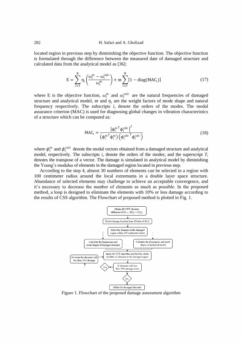
According to the step 4, almost 30 numbers of elements can be selected in a region with
100 centimeter radius around the local extremums in a double layer space structure.
Abundance of selected elements may challenge to achieve an acceptable convergence, and
it’s necessary to decrease the number of elements as much as possible. In the proposed
method, a loop is designed to eliminate the elements with 10% or less damage according to
the results of CSS algorithm. The Flowchart of proposed method is plotted in Fig. 1.
Figure 1. Flowchart of the proposed damage assessment algorithm

APPLICATION OF FINITE ELEMENT MODEL UPDATING FOR DAMAGE …
283
3. NUMERICAL EXAMPLES AND RESULTS
In order to show the capabilities of the proposed approach for identifying multiple structural
damages, three illustrative type of space structures with nine different damage scenarios are
considered.
Space Structure consists of steel truss elements (tubular part) and connectors (ball joint).
The MERO jointing system is a multidirectional system allowing up to fourteen tubular
members to be connected together at various angles. In a double-layer space structure, the
ball joint system can be subjected to tension or compressive axial forces. The system
consists of tubular elements that connected together by MERO jointing system. Details of
connecting system and MERO ball joints are shown in Fig. 2.
Figure 1. (a) MERO jointing system with four tubular elements; (b) member of the double layer
grid; (c) details of the MERO jointing system
According to step one, a three phases design procedure is implemented to perform an
eigenvalue analysis to calculate the mode shapes of space frames. The programming
language Formian is utilized to create the polyhedric configuration of space frames,
including node coordinates. The outcome geodesic forms of space frames are exported to
SAP2000. The general views of selected space frames in SAP2000 are depicted in Fig.3. Geometric properties of introduced double layer diamatic dome, double layer grid and
double layer pyramid are illustrated in Table 1.
In the second step, the imported geometric data in SAP2000 is exploited to design
structural elements. It is assumed that tubular part has uniform area and material properties
along its length. This part is modeled well enough using beam element and constructed from
the components which are generally utilized in practice with the modulus of elasticity
𝐸 = 200 K𝑁/m𝑚2, density 𝜌 = 800 𝑘𝑔/𝑚3, yield stress 0.25 K𝑁/m𝑚2 and the Poisson’s
ratio 𝜇 = 0.3. The tubular parts are modeled by one-dimensional frame element with six
degrees of freedom at each of its two nodes and designed according to the LRFD AISC [33]
provision.

H. Safari and A. Gholizad
284
Table 1: The structural properties of sample systems
Frame type Property Value (unit)
Double layer diamatic
dome
Radius of top circum sphere 50 (m)
Radius of bottom circum sphere 48.5 (m)
Sweep angle 40
Frequency of top layer 16
Number of sectors 6
Double layer grid
Length in x-direction 45 (m)
Length in y-direction 45 (m)
Depth of grid 1.5 (m)
Frequency in x-direction 30
Frequency in y-direction 30
Double layer pyramid
Length of each side of base 30 (m)
Height of pyramid 20 (m)
Distance between two layers 1.25 (m)
Frequency in each side 20
Number of sides of the base 6
Figure 2. (a) General view of the double-layer diamatic dome for Case I; (b) general view of
the double-layer grid for Case II; (c) general view of the
In the last step, the designed section properties of tubular parts and geometric properties
imported from SAP2000 is used to carry out the set of modal analyses in the open-source
finite-element package Opensees. The analytical Opensees model, consists of nodes
coordinate, material properties and section assignments.

APPLICATION OF FINITE ELEMENT MODEL UPDATING FOR DAMAGE …
285
Opensees is used to perform an eigenvalue analysis and calculate the mode shapes of the
intact and damaged space structure. Opensees software is linked to MATLAB to perform
the wavelet analyses and the vertical displacement of mode shape is selected as the input
data. The isosurface of first natural frequency for sample systems with equal elevation on
(𝑥, 𝑦) plane are illustrated in Fig. 4.
Figure 3. Isosurface of the first natural frequency for the intact model: (a) Case I; (b) Case II; (c)
Case III
The 2D-CWT analysis with Mexican hat mother wavelet is applied to the isosurface
generated by the fundamental mode shape. The isosurface is treated as 2D spatially
distributed signals in the form of a matrix, corresponding to the vertical displacement of the
joints along the x- and y-directions, respectively (table 2).
Table 2: Geometric properties of sample systems
Case No. Matrix dimension Number of elements Number of joints
I 2352*2352 9216 2352
II 1861*1861 7200 1861
III 2521*2521 10980 2521

H. Safari and A. Gholizad
286
Nine damage scenarios are selected to evaluate the applicability of introduced method.
Both of tubular parts and ball joints are vulnerable and could be suffered damage in a space
structure. Here, damage is considered as a reduction of stiffness, which is incorporated into
the equations by a reduction in the Young’s modulus of damaged element. Damage can be
simulated in the ball joint by a reduction in the stiffness of all its connected tubular parts.
The reduction stiffness in damaged elements for all scenarios is expressed in the last column
in Table 3.
Table 3: Damage scenarios of sample systems
Scenario No. Case Damaged
elements
Damaged
Joints
Coordinate on isosurface Damage
(%) x y
1 I 6391 - 52 17 50
2 I - 1282 36 24 70
3 I - 503 108 40 80
1669 18 48 60
4 II - 728 73 22 85
5 II 1121 - 28 31 90
6 II 1133 28 67 65
1536 70 16 80
7 III - 578 82 33 90
8 III - 954 37 34 80
9 III
10597
58 97
100
10599 90
10637 80
The introduced scenarios are selected intently to investigate four main goals. Sensitivity
of the proposed method to slight damage, the ability to detect damage in joints and tubular
parts, multiple structural damage localization and quantification and the ability of fast
damage detection for all types of space frames.
Damage index 𝐷(𝑥,𝑦) from Eq. 19 is applied to minimize these effects. According to the
denoised data modified in step 4, the final results for introduced scenarios are illustrated in
Fig. 5.
APPLICATION OF FINITE ELEMENT MODEL UPDATING FOR DAMAGE …
287
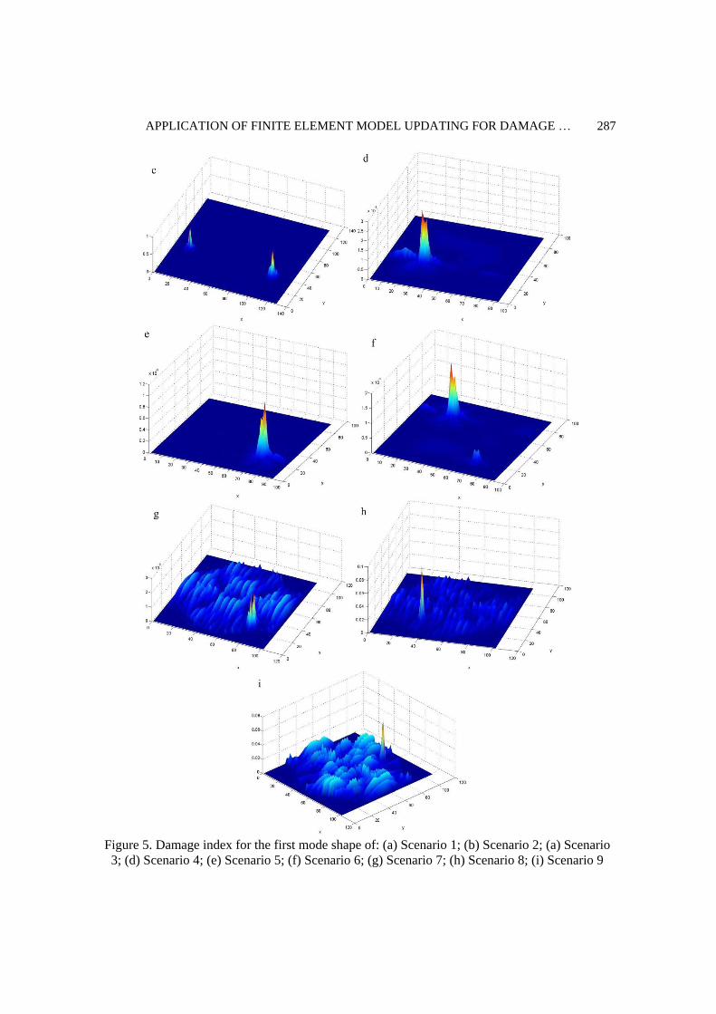
Figure 5. Damage index for the first mode shape of: (a) Scenario 1; (b) Scenario 2; (a) Scenario
3; (d) Scenario 4; (e) Scenario 5; (f) Scenario 6; (g) Scenario 7; (h) Scenario 8; (i) Scenario 9

H. Safari and A. Gholizad
288
Fig. 5 show the smoothed surface generated based on the positional damage index
𝐷(𝑥,𝑦). The results show that, index D is a good indicator for damage detection. As the
results, the noisy pattern of modified data or intensity of index D is variable and ascends
according to the severity of damage imposed on the structure.
To investigating the applicability of the proposed approach on structural damage
quantification, the coordinates of damages defined in the previous steps and the modal
parameters (frequencies and mode shapes) of intact and damaged structure are applied as the
input to the CSS algorithm. The number of modes used should be selected intently to
maintain proper balance between the robustness of the algorithm, and the effort put into
providing the data. While using more data helps the algorithm to converge to the right state
of damage in a larger portion of runs, it generally needs considerably more effort. Here, first
seven natural frequencies are considered for the assessment of damages in all Examples. The
number of CPs increases the search strength of the algorithm as well as the computational
cost and vice versa a small number causes a quick convergence without performing a
complete search. A population of 20 CPs is used for single damage cases, and 25 CPs is
used for the multiple damage cases. A maximum number of iterations of 150 are used as the
termination criterion in all the examples.
Double layer diamatic dome is considered as the first numerical example. Natural
frequencies for seven mode shapes of intact and damaged structures are presented in Table 3.
Table 4: Natural frequencies of the intact and damaged structures (Double layer diamatic dome-
Case I)
Frequency number Intact structure Scenario No.
1 2 3
1 43.340 43.336 43.281 43.238
2 43.342 43.341 43.308 43.253
3 45.235 45.235 45.184 45.149
4 59.556 59.550 59.497 59.479
5 59.559 59.557 59.538 59.511
6 63.103 63.101 62.985 62.892
7 63.110 63.110 63.106 63.060
According to the damage coordinates, resulted from 2D-CWT analysis, 21, 21 and 40
elements is selected in scenario 1, 2 and 3, respectively to perform FEMU analysis and
defining the amount of damage on elements. Variation of the objective function with the no.
of iteration is shown in Fig. 6.
In the second case, Double layer grid is considered. Frequencies of the first seven mode
shapes of intact and damaged structure is presented in table 5 according to the damage
scenarios 4, 5 and 6.

APPLICATION OF FINITE ELEMENT MODEL UPDATING FOR DAMAGE …
289
Figure 6. Variation of normalized objective function with no. of iteration for scenarios of case I
Table 2: Natural frequencies of the intact and damaged structures (Double layer grid -Case II)
Frequency number Intact structure Scenario No.
1 2 3
1 23.141 23.126 23.098 23.136
2 33.148 33.092 33.097 33.129
3 33.148 33.148 33.148 33.148
4 43.077 42.994 43.056 43.048
5 75.465 75.425 75.413 75.460
6 77.575 77.283 77.508 77.521
7 78.650 78.305 78.550 78.510
Fig. 7 shows the normalized objective function with iteration for 20, 18 and 39 selected
elements in the damaged locations of scenarios 4, 5 and 6 respectively.
Figure 4. Variation of normalized objective function with no. of iteration for scenarios of case II

H. Safari and A. Gholizad
290
The convergence history of 24, 23 and 20 elements in the damaged locations for
scenarios 7, 8 and 9 are plotted in Fig.8, respectively.
Table 3: Natural frequencies of the intact and damaged structures (Double layer pyramid - Case III)
Frequency number Intact structure Scenario No.
1 2 3
1 58.928 58.853 58.844 58.907
2 58.928 58.918 58.922 58.928
3 66.444 66.360 66.344 66.408
4 66.445 66.406 66.397 66.445
5 74.373 74.300 74.291 74.353
6 84.616 84.549 84.597 84.614
7 94.102 93.977 93.958 94.034
Figure 5. Variation of normalized objective function with no. of iteration for scenarios of case III
According to the results of FEMU, error from the exact damage for each element in the
damaged region defined by 2D-CWT is illustrated in Fig. 9 for scenario 1. It is worth to
remind here that the more distant from zero these plots are, the worse the performance of a
given algorithm is.
Figure 6. Errors from the exact damage of elements in scenario 1

APPLICATION OF FINITE ELEMENT MODEL UPDATING FOR DAMAGE …
291
The mean error from exact damage for all damage scenarios are plotted in Fig. 10.
Figure 7. The mean error from exact damage for all damage scenarios
The results reveal that the applied optimization algorithm and proposed FEMU method is
completely capable of multiple damage localization in different types of space structures.
4. CONCLUSIONS
The main objective of this heuristic study is to evaluate the performance of an evolutionary
strategy in the finite element model updating approaches for damage assessment in space
structures. Based on the continuous wavelet transform, the location of damaged joints or
tubular parts are defined according to mode shapes of damaged and intact structure to
increase the calculation costs of damage assessment. The finite element model updating
method has been implemented as an inverse optimization problem by applying the charged
system search algorithm to assess the severity of damage in each element sited in the
damage region.
Nine different numerical examples on three different shape of space structure were
studied in order to show the advantages of proposed method. Referring to the results of these
examples, the usefulness, Simplicity and flexibility of the proposed method in defining the
amount of elements damage is demonstrated.
The numerical results demonstrate that the combination of the 2D-CWT algorithm
together with finite element model updating concepts can provide an efficient tool for
properly identifying the multiple damages in all types of space structures without any
limitation on size and shape of structure.
REFERENCES
1. Kaveh A, Zolghadr A: An improved CSS for damage detection of truss structures using
changes in natural frequencies and mode shapes, Adv Eng Softw 2015; 80: 93-100.
2. Gholizad A, Safari H: Two-dimensional continuous wavelet transform method for
H. Safari and A. Gholizad
292
multidamage detection of space structures, J Perform Construct Facili 2016, 13(3) DOI:
10.1061/(ASCE)CF.1943-5509.0000924.
3. Roveri N, Carcaterra A. Damage detection in structures under traveling loads by
Hilbert–Huang transform, Mech Syst Signal Process 2012, 28: 128-44.
4. Quek ST, Tua PS, Wang Q: Detecting anomalies in beams and plate based on the
Hilbert–Huang transform of real signals, Smart Mater Struct 2003, 12: 447.
5. Xu W, Radzieński M, Ostachowicz W, Cao M. Damage detection in plates using two -
dimensional directional Gaussian wavelets and laser scanned operating deflection
shapes, Structural Health Monitor 2013; 12(5-6) 457-68.
6. Yun GJ, Lee SG, Carletta J, Nagayama T. Decentralized damage identification using
wavelet signal analysis embedded on wireless smart sensors, Eng Struct 2011, 33: 2162-
72.
7. Bharathi Priya C, Likhith Reddy A. Low frequency and boundary condition effects on
impedance based damage identification, Case Studies Nondestructive Test Evaluat 2014;
2: 9-13.
8. Hamzeloo SR, Shamshirsaz M, Rezaei SM. Damage detection on hollow cylinders by
electro-mechanical impedance method: experiments and finite element modeling,
Comptes Rendus Mécanique 2012; 340: 668-77.
9. Strang G, Nguyen T. Wavelets and Filter Banks, SIAM, 1996.
10. Haar A. Zur Theorie der orthogonalen Funktionensysteme, Mathemat Annalen 1910, 69:
331-71.
11. Surace C, Ruotolo R. Crack detection of a beam using the wavelet transform. In The
International Society for Optical Engineering, Poit International Society for Optical
1994: 1141-47.
12. Zhong S, Oyadiji SO: Detection of cracks in simply-supported beams by continuous
wavelet transform of reconstructed modal data, Comput Struct 2011, 89: 127-48.
13. Song YZ, Bowen CR, Kim HA, Nassehi A, Padget J, Gathercole N, Dent A: Non-
invasive damage detection in beams using marker extraction and wavelets, Mech
Systems Signal Process 2014; 49: 13-23.
14. Xiang J, Liang M: Wavelet-based detection of beam cracks using modal shape and
frequency measurements, Comput-Aided Civil Infrastruct Eng 2012; 27: 439-54.
15. Fan W, Qiao P. A 2-D continuous wavelet transform of mode shape data for damage
detection of plate structures, Int J Solids Struct 2009; 46: 4379-95.
16. Katunin A. Damage identification in composite plates using two-dimensional B-spline
wavelets, Mech Syst Signal Process 2011, 25: 3153-67.
17. Xu W, Cao M, Ostachowicz W, Radzieński M, Xia N: Two-dimensional curvature mode
shape method based on wavelets and Teager energy for damage detection in plates, J
Sound Vib 2015, 347: 266-78.
18. Xiang J, Matsumoto T, Wang Y, Jiang Z: Detect damages in conical shells using curvature
mode shape and wavelet finite element method, Int J Mech Sci 2013, 66: 83-93.
19. Baneen U, Kinkaid NM, Guivant JE, Herszberg I: Vibration based damage detection of a
beam-type structure using noise suppression method, J Sound Vib 2012, 331: 1777-88.
20. Makki Alamdari M, Li J, Samali B: FRF-based damage localization method with noise
suppression approach, J Sound Vib 2014, 333: 3305-20.
21. Avci O, Abdeljaber O. Self-organizing maps for structural damage detection: a novel

APPLICATION OF FINITE ELEMENT MODEL UPDATING FOR DAMAGE …
293
unsupervised vibration-based algorithm, J Perform Construct Facilit 2015, 0:04015043.
22. Doebling SW, Farrar CR, Prime MB, Shevitz DW. Damage identification and health
monitoring of structural and mechanical systems from changes in their vibration
characteristics: A literature review, In Other Information: PBD: May 1996, Edited by;
1996: Medium: ED; Size: 132 p.
23. Majumdar A, Maiti DK, Maity D: Damage assessment of truss structures from changes
in natural frequencies using ant colony optimization, Appl Math Comput 2012, 218:
9759-72.
24. Ding ZH, Huang M, Lu ZR: Structural damage detection using artificial bee colony
algorithm with hybrid search strategy, Swarm Evolutionary Comput 2016, 28:1-13.
25. Seyedpoor SM. A two stage method for structural damage detection using a modal strain
energy based index and particle swarm optimization, Int J Non-Linear Mech 2012, 47: 1-8.
26. Shayanfar MA, Kaveh A, Eghlidos O, Mirzaei B: Damage detection of bridge structures
in time domain via enhanced colliding bodies optimization, Int J Optim Civil Eng 2016,
6: 211-26.
27. Shiradhonkar SR, Shrikhande M: Seismic damage detection in a building frame via
finite element model updating, Comput Struct 2011; 89: 2425-38.
28. Fu YZ, Lu ZR, Liu JK: Damage identification in plates using finite element model
updating in time domain, J Sound Vib 2013, 332: 7018-32.
29. Nhamage IA, Lopez RH, Miguel LFF: An improved hybrid optimization algorithm for
vibration based-damage detection, Adv Eng Softw 2016, 93: 47-64.
30. Kaveh A, Talatahari S: A novel heuristic optimization method: charged system search,
Acta Mech 2010; 213: 267-89.
31. Rucka M, Wilde K: Application of continuous wavelet transform in vibration based
damage detection method for beams and plates, J Sound Vib 2006, 297: 536-50.
32. Hildreth EC. Computations underlying the measurement of visual motion, Artificial
Intell 1984, 23: 309-354.
33. AISC: Resistance factor design specification for structural steel buildings, Edited by
Chicago: American Institute of Steel Construction, 1999.
34. Gallego A, Moreno-García P, Casanova CF: Modal analysis of delaminated composite
plates using the finite element method and damage detection via combined Ritz/2D-
wavelet analysis, J Sound Vib 2013, 332:2971-2983.
35. Castro E, García-Hernandez MT, Gallego A. Damage detection in rods by means of the
wavelet analysis of vibrations: Influence of the mode order, J Sound Vib 2006, 296:
1028-38.
36. Marwala T. Finite Element Model Updating Using Computational Intelligence
Techniques: Applications to Structural Dynamics, Springer Science & Business Media,
2010.