Application of Ca-based geopolymer with blast furnace€¦ · geopolymer with blast furnace slag...
18
Transcript of Application of Ca-based geopolymer with blast furnace€¦ · geopolymer with blast furnace slag...


2nd International Slag Valorisation Symposium | Leuven | 18-20/04/2011 33
Application of Ca-based geopolymer with blast furnace slag, a review
Joseph DAVIDOVITS
Geopolymer Institute, 16 rue Galilée, 02100 Saint-Quentin, France
Abstract
We present the differences that occur in the chemical mechanism of “alkali-activated
slag” and slag-based geopolymer. The negative aspects of alkali-activation are
essentially due to corrosive mixture conditions, coined “user-hostile” when compared
with the mild milieu that governs geopolymerisation, coined “user-friendly”. Ca-based
geopolymer with blast furnace slag generates lower CSH and Al(OH)3 content,
yielding three-dimensional molecular structures of the anorthite hydrate type
embedded in a solid solution comprising poly(sialate) and poly(sialate-disiloxo)
structures. One distinguishes 3 types of Ca-based geopolymer, namely: 1) MK-
750/slag-based used for toxic and radio-active waste management; 2) Rock/slag-
based for cement in building and infrastructure; 3) Fly ash/slag-based for geopolymer
concrete.
Introduction
Davidovits coined the term geopolymer in 1978 to represent a broad range of
materials characterised by chains or networks of inorganic molecules.1 Iron blast
furnace slag-based geopolymer research started in 1983 at the Central Laboratory of
a major American cement company, Lone Star Industries, Inc, Houston, Texas, USA
where Davidovits and Sawyer developed a geopolymer cement, later coined
Pyrament cement.2 In the 1930’s, alkalis, such as sodium and potassium hydroxide,
were originally used to test iron blast furnace ground slag to determine if the slag
would set when added to Portland cement. In the course of studying the testing
systems for slag, the Belgian scientist Purdon3 discovered in 1940 that the alkali
addition produced a new, rapid-hardening binder. Alkali-activated slag cements
(called Trief cements) were used in large-scale construction as early as the 1950’s.
The usual alkalination called for adding 1.5 percent NaCl and 1.5 percent NaOH to 97
percent ground slag mix (U.S. Army Engineer Waterways Experiment Station, 1953).
In 1957, the Ukrainian scientist Victor Glukhovsky4 developed alkali-activated slag
binders for building applications.

2nd International Slag Valorisation Symposium | Leuven | 18-20/04/2011 34
Geopolymerisation mechanism with iron blast furnace slag
The mineral composition of the slag glassy phase is mainly composed of melilite, a
solid solution of gehlenite Ca2Al2SiO7 plus akermanite Ca2Mg(Si2O7) (Figure 1) and
also merwinite Ca3Mg(SiO4)2 . Aluminium is only found in gehlenite and magnesium
akermanite and merwinite. From a geopolymeric chemistry point of view, gehlenite
is the reactive molecule with effective potential as geopolymeric precursor.
Geopolymerisation starts with the alkalination step involving NaOH or KOH. Its
mechanism can be followed with MAS-NMR spectroscopy.
In 29Si NMR, the several resonances around -76 ppm for untreated slag (Figure 2a)
are characteristic of the resonance reported by Kirkpatrick5 for akermanite glass and
solid solution of gehlenite glass. They are assigned to Q1 species in akermanite glass
and to Q2(2Al) in gehlenite glass. The alkalination with KOH (5 M) performed by
Richardson et al.6 (Figure 2b) produced a shift to -79 ppm for hydrated Q1 units of
akermanite and a strong line at -82 ppm for hydrated Q2(1Al) elements in gehlenite.
The shoulder around -76 ppm is assigned to unreacted glass and is not taken into
account.
In 27Al NMR, the broad resonance at 58.05 ppm (Figure 3a) reflects the presence of Al
in highly distorted tetrahedral configuration within the gehlenite glass fraction. On
alkalination with KOH (Figure 3b) there is a narrowing and sharpening of this peak
and a shift to 63 ppm, a shoulder around 70 ppm and presence of a new narrow
resonance at 10 ppm typical for Al in 6-fold coordination. Richardson and Groves7
had shown the presence in hardened blast furnace slag of layers with Mg, Al
hydroxide phase related to the naturally occurring mineral hydrotalcite
[Mg0.75Al0.25(OH)2](CO3)0.125(H2O)0.5. Alkalination with KOH and NaOH liberates
Mg(OH)2 and Al(OH)3, Al in 6-fold coordination which precipitate or react with
atmospheric CO2.
Figure 1: Molecular structure of gehlenite and akermanite in melilite glass

2nd International Slag Valorisation Symposium | Leuven | 18-20/04/2011 35
Figure 2: 29Si NMR; a) (left) untreated slag; b) (right) alkalination with KOH
The alkalination and dissolution of gehlenite glassy slag produces low molecular Q1
and Q2(1Al), Q2 species, monomers, dimers, and several hydroxides. Yet, according to
Astutiningsih and Liu8 the major drawback in utilising blast furnace slag for
geopolymers is the high content of CaO, composing 41% of the precursor’s total
weight. These authors believe that CaO, which is integrated in the gehlenite,
akermanite and merwinite phases, does not interfere with the geopolymerisation of
the alumina-silica constituents. During mixing, Ca++ would react with OH- in the
alkaline aqueous system to form Ca(OH)2, which then reacts with CO2 in the
atmosphere, forming calcite, CaCO3. According to them, these reactions would be in
essence the hardening mechanism of mortar. At the same time, dissolution of
alumina-silica precursor proceeds.
Figure 3: 27Al NMR; a) (left) untreated slag; b) (right) alkalination with KOH.
2nd International Slag Valorisation Symposium | Leuven | 18-20/04/2011 36
However, our laboratory experience shows that carbonation into CaCO3 or MgCO3
does not occur in the reaction mixture, but later, after the geopolymer has set and
comes in contact with the atmosphere, during the first drying process. Hardening is
therefore only governed by geopolymerisation. Alkalination induces the splitting of
the Al-O-Al sequence in Ca-poly(alumino-sialate) glass, gehlenite. One Al atom
participates in geopolymerisation, the second goes into the solution as the Mg. The
chemical mechanism of the alkalination of melilite glass may be interpreted in this
way.
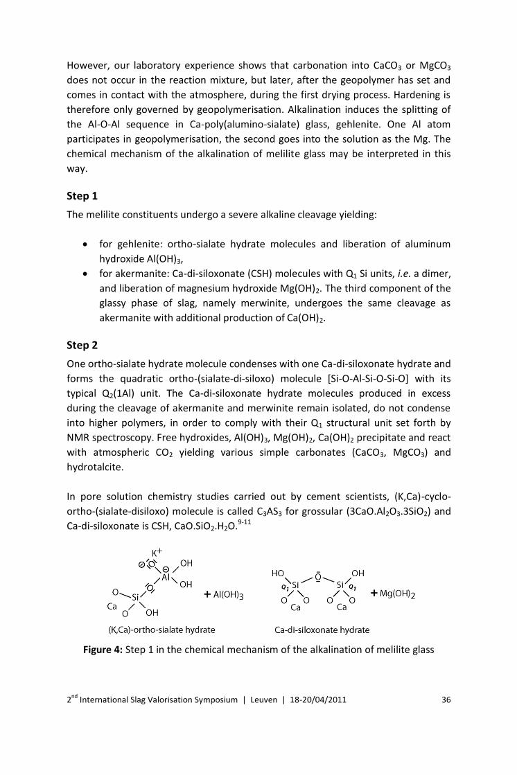
Step 1
The melilite constituents undergo a severe alkaline cleavage yielding:
for gehlenite: ortho-sialate hydrate molecules and liberation of aluminum
hydroxide Al(OH)3,
for akermanite: Ca-di-siloxonate (CSH) molecules with Q1 Si units, i.e. a dimer,
and liberation of magnesium hydroxide Mg(OH)2. The third component of the
glassy phase of slag, namely merwinite, undergoes the same cleavage as
akermanite with additional production of Ca(OH)2.
Step 2
One ortho-sialate hydrate molecule condenses with one Ca-di-siloxonate hydrate and
forms the quadratic ortho-(sialate-di-siloxo) molecule [Si-O-Al-Si-O-Si-O] with its
typical Q2(1Al) unit. The Ca-di-siloxonate hydrate molecules produced in excess
during the cleavage of akermanite and merwinite remain isolated, do not condense
into higher polymers, in order to comply with their Q1 structural unit set forth by
NMR spectroscopy. Free hydroxides, Al(OH)3, Mg(OH)2, Ca(OH)2 precipitate and react
with atmospheric CO2 yielding various simple carbonates (CaCO3, MgCO3) and
hydrotalcite.
In pore solution chemistry studies carried out by cement scientists, (K,Ca)-cyclo-
ortho-(sialate-disiloxo) molecule is called C3AS3 for grossular (3CaO.Al2O3.3SiO2) and
Ca-di-siloxonate is CSH, CaO.SiO2.H2O.9-11
Figure 4: Step 1 in the chemical mechanism of the alkalination of melilite glass

2nd International Slag Valorisation Symposium | Leuven | 18-20/04/2011 37
Figure 5: Step 2 in the chemical mechanism of the alkalination of melilite glass
Alternative step
According to cement scientists, the alkalination of glassy gehlenite slag is similar to
the hydration of Portland cement paste into calcium silicate hydrate, written
CSH.7,12,13 Instead of the simple dimer, Ca-di-siloxonate hydrate, typical for CSH,
Richardson et al.6 suggest the incorporation of a bridging function for the aluminium
atom, between two dimer molecules. They describe a tobermorite linear chain
structure with Al substitution. However, alumino-silicate molecules, geopolymer
precursors, oligomers, form cyclic structures, quadratic, pentahedral or hexahedral
arrangements, not linear molecules. The chemical mechanism set forth in Step 1 and
Step 2 is, therefore, more representative of the alkalination of gehlenite glassy slag
than the linear alternative step.
Negative aspect of alkalination
For Astutiningsih and Liu8 the major drawback in utilising blast furnace slag is the
high content of CaO. The truth is that the main negative aspect is the alkalination
itself. In the ortho-sialate-di-siloxo molecule generated in Step 2 (as well as in the
tobermorite of the Alternative step), the alkalis K+ or Na+ are located at a non-
bridging oxygen site Al-O- K+. The cation is not attached chemically or trapped
physically by the structure. It may move and build free alkalinity KOH or NaOH.
Several studies14-16 demonstrate that, in alkali-activated slag, Na and K are not
structurally incorporated but are physically adsorbed onto the surface structure.
Despite this negative aspect, alkalination has been promoted for cementitious
systems and coined “alkali-activated slag” by Glukhovsky and others.17-25 They built a
storehouse in 1974 made of alkali-activated slag. Deja26 studied the evolution of the
free alkalinity remaining in the pore solutions of this concrete. The amount of free
alkali did not change from 28 days (35.6%) to 27 years (38%). However, the industrial
implementation of iron blast furnace slag in geopolymeric systems requires the
absence of free alkali in the geopolymer matrix. This implies the development of
“User-friendly” systems.
2nd International Slag Valorisation Symposium | Leuven | 18-20/04/2011 38
Development of user-friendly geopolymeric systems
Material Safety Data Sheets provide a classification of alkaline chemicals ordered in
two categories: corrosive products and irritant products. The two classes are
recognizable through their respective logos displayed in Figure 6.
Table 1: Corrosive and irritant chemicals
Corrosive: User-hostile Irritant: User-friendly
CaO (quick lime) Ca(OH)2 NaOH Portland cement
KOH Iron slag
Sodium metasilicate
SiO2:Na2O = 1
Slurry soluble silicate/kaolin
MR 1.25<SiO2:M2O<1.45
Any soluble silicate
MR SiO2:M2O <1.45
Any soluble silicate
MR SiO2:M2O >1.45
Table 1 lists some alkaline chemicals and their corresponding safety label. The
corrosive products must be handled with gloves, glasses and masks. They are user-
hostile and cannot be implemented in mass applications without the appropriate
safety procedures. In the second category one finds Portland cement or hydrated
lime, typical mass products. Those geopolymeric ingredients belonging to this class
may also be termed user-friendly. When we started the research on geopolymers we
decided to select alkaline conditions that could be classified as merely “irritant”, i.e.
user-friendly.
The alkaline conditions were reached with a MR ratio SiO2:M2O > 1.45, and as it
turned out, SiO2:M2O = 1.85. Unfortunately, our recommendation was not followed
by other engineers and scientists involved in the development of geopolymeric
systems, or “alkali-activation”. Table 2 provides details on recently published patents
dedicated to “geopolymer” cements, based or not on iron blast furnace slag.
Figure 6: Logos for corrosive (left) and irritant (right) chemicals

2nd International Slag Valorisation Symposium | Leuven | 18-20/04/2011 39
Table 2: Comparison between state of the art patents
WO 03/
099738
WO 05/
019130
US 508
4102
US 464
2137
CZ 289
735
WO 03/
078349
US 560
1643
MK-750 XX XX -- XX XX -- --
slag XX XX XX XX XX -- --
Fly ash -- XX (C,F)) XX (F) XX (C,F) XX XX (C) XX (F)
SiO2:M2O 1.25-2.0 0.31 0.8-1.20 3.0 0.4-1.0 0.6-1.0 0.2-1.0
temperature 20°C 90°C 20°C 20°C 60-70°C 20-95°C 60-90°C
time - 12-18h - - 8-12h 8-12h 15-60h
activator --
Borax clinker KOH +
clinker clinker Ca++ --
USER-
FRIENDLY YES NO NO NO NO NO NO
XX indicates the presence of the ingredient in the recipe
This is not an exhaustive list but it shows that the mainstream of researchers,
scientists and engineers, do not consider the end user’s safety at all. Only one patent,
WO O3/099738, out of eight presents a user-friendly SiO2:M2O ratio in the range of
1.25-2.0. In all cited patents, except one, the safety label states “user-hostile”.
Another problem is also that practically all papers dealing with “alkali-activated”
cements describe recipes that are user-hostile. For example, Glukhovsky,4 Krivenko,24
Palomo et al.27 suggest the use of sodium metasilicate MR = 1. Van Jaarsveld and van
Deventer28 get the best results for MR ranging between 0.69 and 1.11. Others
present even stronger alkaline conditions, like Astutiningsih and Liu8 who keep the
MR in the range of 0.60. All these alkaline conditions are corrosive to strongly
corrosive. Although, during the Geopolymer 2005 Conference in Saint-Quentin, end
users representatives complained about this situation, several scientists do not take
this situation into account and continue to promote user-hostile systems. See for
example the recent review by Duxson et al.29
Chemistry mechanism of MK-750/slag-based geopolymer matrix
In order to better understand the chemistry of Ca-based geopolymer matrix we make
the following geopolymeric mixture, called Cement Base in various documents:30-32
Calcined kaolinitic clay MK-750
aluminosilicate oxide (Si2O5, Al2O2), 0, 20 and 30 parts
K silicate solution,
(by weight) K2O: 26%, SiO2: 21%, H2O: 53% 25 parts

2nd International Slag Valorisation Symposium | Leuven | 18-20/04/2011 40
Blast furnace slag (calcium melilite)
average grain size 8 microns 27 parts
Water 31 parts
Subsequently, we pour the mixture into a container covered with a plastic film or a
lid and allow to harden at room temperature. The interaction of MK-750 neutralises
any risks of free alkalinity. Its action may be followed with MAS-NMR spectroscopy.
Figure 7 plots the 8-day compressive strength for different MK-750 contents added
to slag. It shows that the strength diminishes with the increase of MK-750.
The knowledge on the chemical structural make-up of this hardened Ca-based
geopolymer matrix is essential for the understanding towards long-term behaviour.
MAS-NMR Spectroscopy
The NMR spectra in Figure 6 show the transformation from the simple alkali
activated slag (no MK-750 addition) into a three-dimensional alumino-silicate
network typical for equilibrated geopolymer. In the 29Si NMR spectrum, the major
resonance at - 82/-83 ppm in alkali-activated slag (no MK-750 added) is similar to the
one of Figure 2b discussed previously for KOH alkalination. They can be assigned to
Q2(1Al) and Q2 species. The addition of 20 parts MK-750 shifts the resonances to -86
ppm assigned to Q3 branched units. The resonance is broader, with values at -88 and
around -90 ppm, suggesting the formation of Q4 networking elements. With the
addition of 30 parts MK-750 the shifts reaches -88, -90, -92 and higher, suggesting
three-dimensional networking of the types Q4(3Si.1Al), Q4(2Si.2Al), Q4(1Si.3Al) and
Q4(4Al).
Figure 7: 8-day compressive strength for different MK-750 contents, after
Geocistem29

2nd International Slag Valorisation Symposium | Leuven | 18-20/04/2011 41
Figure 8: 29Si NMR (left) and 27Al NMR (right) of hardened geopolymeric Cement
Base, evolution from alkali-activated slag towards geopolymer cement: no MK-750
added; middle curve, with 20 parts MK-750; top curve, with 30 parts MK-750
In the 27Al NMR spectrum, the major resonances at 74/65 ppm in alkali-activated slag
(no MK-750 added) are similar to those of Figure 3b discussed previously for KOH
alkalination. They can be assigned to AlQ(2Si.2OH) and AlQ(3Si,OH) species. With the
addition of 30 parts MK-750 the resonance is narrower at 58 ppm suggesting three-
dimensional networking of the type AlQ(4Si). In alkali-activated slag, the peak at 9
ppm is assigned to 6-fold coordinated Al. Its intensity is much smaller than its
equivalent in Figure 3b for KOH alkalination. With geopolymerisation, some
potassium silicate molecules (dimer, trimer and higher) have reacted with the free
Al(OH)3 to generate a geopolymer phase. With the addition of 30 parts MK-750, the
initial amount of 6-fold Al, 8%, drops below 3% and 4-fold Al reaches 97%. The very
small amount of Al(6) may be also explained by some unreacted MK-750, not by the
presence of Al(OH)3.
Both spectra demonstrate that, in opposition to alkali-activated slag, the Al in (Ca,K)
geopolymers is entirely chemically connected, i.e. the cations Na+ and K+ are trapped
within the structure, providing long-term stability and corrosion resistance. End-
users may have a choice between high strength and low stability (alkali-activation) or
lower strength and optimal long-term and corrosion resistance (geopolymerisation).
Electron microscopy
Figure 9 shows the electron micrograph of this Ca-based geopolymer that consists of
an amorphous matrix (shown in black) in which small white grains are embedded.

2nd International Slag Valorisation Symposium | Leuven | 18-20/04/2011 42
Figure 9: Electron micrograph of the Ca-based geopolymer (Scale bar = 10 microns).
The picture on the top right is an enlargement of the central part of the picture with
the imprints of digested slag particles.32
These are remains of the slag. One notices that the majority of the slag grains have
disappeared. One only sees an imprint of their initial shape, in the form of a skin,
probably made up of ingredients which did not react. We may conclude that slag
crystals are digested by the K-silicate slurry, and then react with MK-750, leaving the
imprint of the grain surrounded with materials non-participating into the reaction
(Mg, Ca, Si).
The chemical composition of the amorphous matrix (circle and grain interior)
comprises Si, Al, Ca and K atoms, with practically no Mg, the latter being found in the
white powders and grains. This process is very regular and can be complete within 30
minutes, at ambient temperature. The overall chemical composition for the Ca-based
geopolymer is given as oxides in Table 3. The values for water were omitted
voluntarily.
Table 3: Overall composition of the Ca-based geopolymer mix (water omitted)
SiO2 %
Al2O3
% Fe2O3
% MgO %
CaO %
Na2O %
K2O %
MK-750 16.33 12.76 0.15 0.096 0.012 0.042 0.439
Ca melilite 9.58 3.24 0.054 2.43 11.34 0.054 0.135
K-silicate. 5.23 0 0 0 0 0 6.495
Total oxides by weight
31.15 16.00 0.210 2.52 11.35 0.096 7.069
Total in mole 0.519 0.157 0.063 0.20 0.0015 0.0752

2nd International Slag Valorisation Symposium | Leuven | 18-20/04/2011 43
The oxide mole values provide the following atomic ratios:
Si:Al 1.65 Si:K 3.43
K:Al 0.48 Si:Ca 2.57
Ca:Al 0.64 Si:Mg 8.22
After hardening, the Electron Micro Beam Analysis gives the oxide chemical
composition for the geopolymer matrix in which the calcium melilite grains have
practically all disappeared. Only some coarse grains and small fragments remain with
a size greater than 20 microns. 14 micro beam measurements were made of the
geopolymer matrix. The average value of these measurements provides the following
atomic ratios (between brackets, the lowest and the highest values):
Si:Al 1.655 (1.317 to 1.832) Si:K 2.46
K:Al 0.670 (0.30 to 0.97) Si:Ca 3.75,
Ca:Al 0.44 (0.16 to 0.610) Si:Mg 21.26 (3.73 to 49.33)
Chemistry mechanism, solid solution in MK-750/slag-based geopolymer matrix
It is striking to notice that in the overall composition and in the electron beam
analysis the Si:Al ratio equals 1.65. Each aluminium atom is involved in the
geopolymer matrix, none is found in the slag debris. We know that the negative
charge of every Al atom must be balanced with a corresponding positive charge, i.e.
one K+ or half Ca++. In the matrix, the ratio K:Al equals 0.67, implying that 0.33
positive charge must be found with a Ca double cation, i.e. 0.165 Ca. The negative
charge of one Al is therefore balanced with 0.67 K+ and 0.165 Ca++. The Si:Al ratio =
1.65 is equal to the ratio of 5 Si to 3 Al that could be achieved by mixing several types
of geopolymer molecules:
poly(sialate), Si:Al = 1:1
poly(sialate-disiloxo) Si:Al = 3:1
ortho(di-siloxonate) Si:Al = 1:0
A satisfactory composition would be achieved by having a solid solution of:
2.5 molecules (K,Ca)-poly(sialate), hydrate
0.5 (K,Ca)-poly(sialate-di-siloxo), hydrate
0.5 Ca-di-siloxonate, hydrate (CSH)
The simultaneous presence of Ca-di-siloxonate/CSH in a geopolymer matrix
remained a puzzle for researchers working on geopolymers, until Yip and van

2nd International Slag Valorisation Symposium | Leuven | 18-20/04/2011 44
Deventer33 mentioned that the CSH element formed in the geopolymer matrix had a
significantly lower Ca/Si ratio than the CSH commonly formed from the hydration of
OPC. Actually, we do not have in (K,Ca)-poly(sialate) an alternation between K+ and
Ca++ along the macromolecular chain. Indeed, geological analogues derived from the
melt suggest rather a solid solution between K-poly(sialate), kalsilite, and Ca-poly(di-
sialate), anorthite CaSi2Al2O8, as well as K-poly(sialate-disiloxo), orthoclase-sanidine,
and anorthite. Ca and K would be more probably involved in two parallel chemical
mechanisms yielding the joint formation of a solid solution containing:
1.67[K-poly(sialate)], kalsilite, hydrate + 0.41[Ca-poly(di-sialate)], anorthite
hydrate;
0.33[K-poly(sialate-disiloxo)], orthoclase hydrate, + 0.08[Ca-poly(di-sialate)],
anorthite hydrate;
0.5[Ca-di-siloxonate] (CSH).
Industrial Applications of Ca-based geopolymer
One distinguishes 3 types of Ca-based geopolymer, namely:
1. MK-750/slag-based (calcined kaolinitic clay-based binder);
2. Rock/slag-based (silica-rich rock-based cement);
3. Fly ash/slag-based (class C fly ash-based cement).
Below, we give one example of a successful application for each type.
MK-750/slag–based geopolymer binder for toxic and radio-active waste management
Any safe heavy metals or radioactive containment requires the implementation of a
technology involving MK-750-based geopolymers, exclusively. The disposal of
radioactive and toxic sludge must meet at least two conditions:
1. Safe chemical encapsulation of the contaminants, i.e., prevention of their
release into ground and seepage water in order to minimise the health risks
via the water path. Contaminant release is controlled by the leaching
properties of the immobilisation matrix.
2. Structural stability with respect to adverse environmental conditions such as
rapid changes of temperature and humidity, microbial and chemical
aggression and mechanical stress, in order to guarantee safe handling during
operation time and minimise the risk of uncontrolled spread of contaminated
matter over the next several hundred years.

2nd International Slag Valorisation Symposium | Leuven | 18-20/04/2011 45
In November/December 1998, a pilot-scale experiment was carried out in WISMUT's
Uranium Mine Water Treatment Facility at Aue, Saxen, Germany. This facility was
built to remove Uranium, Radium, Arsenic and other toxic metals from the flooding
water of the Schlema-Alberoda Uranium mine. The technological principle is a
consecutive selective precipitation/flocculation. At a flow rate of about 450 m3/h,
approximately 3.5 to 4 tons of dewatered hydroxide sludges were to be solidified and
disposed of every day. The pilot-scale experimentation involved 20 tons of material.
The user-friendly geopolymer system was safely handled.
Immediately after mixing the pre-product with the MK-750 based (Ca,K)-Poly(sialate-
siloxo) geopolymer cement, the mortar flowed easily into moulds or big bags. After 2
days, 90% of the final compressive strength was reached, and the final compressive
strength of about 20 MPa within 28 days.
Table 4: Leachate concentrations for U, Ra-226 and As
Element Leachate concentration
Unat 1...6 µg/l
Ra-226 < 10 mBq/l
As < 100 µg/l, typ. 10 µg/l
Several leach tests were carried out in order to cover a large range of environmental
stress conditions that may possibly occur over the next centuries. Standard leach
tests according to DIN 38 414-S4 (24 hours, intact 7 cm cubes) were performed to get
information about the overall containment, while sequential leach tests according to
ANS 16.1 (slightly adapted to locally relevant conditions) provide an estimate of the
diffusive transport in the geopolymer matrix. Table 4 gives the results for the
leachate concentrations according to DIN 38 414-S4 while the diffusion constant of
uranium is given in Table 5. Because solid-state processes within the geopolymer
matrix exclusively determine diffusion, the diffusion constants are expected to be
independent of the leachate pH.
Table 5: Diffusion constant D for uranium at pH 3 and pH 5
pH 3 pH 5
D (Uranium) 3.8 x 10⁻¹⁶ cm2/s 1 x 10-16 cm2/s
Rock/slag-based geopolymer cement for building and infrastructure
One takes a rock of the strongly weathered granitic type in which kaolinisation is very
advanced, for example coal mining waste.35 Throughout the world, coal veins are
very often imprisoned between geological layers of kaolinitic granite. Kaolinitic coal-
mining rock waste can be advantageously calcined, because it generally contains

2nd International Slag Valorisation Symposium | Leuven | 18-20/04/2011 46
residual coal that provides additional free energy during calcination at 750°-800°C. It
contains approximately 25% plagioclase (feldspar), 30% quartz, 10% amphibole, 27%
kaolinite, 3% coal and 6% of other elements. It is calcined at 750°C for 3 hours and
ground to an average grain size of 15-25 microns.Then, the following reactive
mixture is prepared:
coal-mining waste, 90 parts
blast furnace slag ground to 15-25 microns 30 parts
K silicate solution,
(by weight) K2O:26%, SiO2:21%, H2O:53% 30 parts
water 20 parts
Ambient temperature hardening yields a compressive strength of 40 MPa at 7 days,
and 105 MPa at 28 days.
Sometimes, with naturally ignited coal, the heat was sufficient to transform kaolinite
into MK-750. Such natural layers exist in several countries for example in Australia
and Czech Republic and deserve to be exploited. In this particular case, there is no
need for calcination so that the saving in energy and the reduction of CO2 emissions
are the highest, in the same order as for fly ash-based geopolymer cements.
Fly ash/slag-based geopolymer cement for geopolymer concrete
The EU sponsored project “Understanding and mastering coal fired ash
geopolymerisation process in order to turn potential into profit”, is known under the
acronym GEOASH (2004-2007).36,37 Normally, curing of alkali-activated fly ash is done
at temperatures between 60 and 90°C. In this technology, since the idea is to use the
geopolymer as a cement, the curing is taking place at ambient temperature, due to
the (Ca,K) geopolymer/slag-based system. Seventeen European fly ashes were
tested. Two methods were used and compared with. One, called the classical or
conventional method, relies on alkali-activation. The second is based on
geopolymerisation with (Ca,K) geopolymeric systems.
Conventional method: alkali-activation, dissolution and zeolite formation. The best
compressive strength values for the conventional alkali-activated method were
obtained by applying the following conditions: 0.3-0.4 L/kg, NaOH 12 M, mixture 5-
10 min, ultrasonic vibration, 24 h room temperature, curing at 80oC for 48h. These
are very caustic user-hostile conditions. KOH is not optimal for the
geopolymerisation following the conventional method, since high concentrations are
required to obtain compressive strengths that are far lower (mostly 90% lower) than
those obtained when NaOH with similar concentration is used.

2nd International Slag Valorisation Symposium | Leuven | 18-20/04/2011 47
Figure 10: 28 day compressive strength; comparison between alkali-activated
(conventional) and geopolymeric processes (GEOASH)36,37
Geopolymeric method: room temperature hardening, polycondensation. The (K,Ca)-
poly(sialate-siloxo) process is based on the system fly ash/slag/Ksil/H2O reacting at
room temperature. The ashes, 60-80% by weight of the mix, were mixed with the
geopolymeric slurry containing K-silicate solution (molar SiO2:K2O > 1.40), blast
furnace slag and water, the various required chemical components used in (K,Ca)-
poly(sialate-siloxo) cement and cured at room temperature. The best compressive
strength values, in the 70-100 MPa range, for the geopolymeric method were
obtained by applying the following conditions: 10 g K-silicate solution, 15 g slag, 5 g
water, 50 g to 85 g fly ash. These are user-friendly handling methods.
For a given fly ash, the conventional alkali-activation (zeolitic method) provides lower
compressive strength than the (Ca,K)-based geopolymeric procedure (Figure 10). It
can be deduced that the geopolymeric method yields higher strengths as well as
lower costs (no thermal activation needed) and safer and easier handling treatment,
i.e. user-friendly.
Conclusion
Slag-based geopolymer binders and cements are a real alternative to conventional
Portland cement for use in toxic waste management as well as transportation
infrastructure and construction. They rely on minimally processed natural materials
and industrial by-products to significantly reduce the carbon footprint of cement
applications, while also being very resistant to many of the durability issues that can
plague conventional concrete. User-friendly slag-based geopolymer cements that can
be used under conditions similar to those suitable for Portland cement are the
current focus of extensive worldwide research efforts. These cements are capable of
being mixed with a relatively low-alkali activating solution and must cure in a
reasonable time under ambient conditions. The production of versatile, cost-

2nd International Slag Valorisation Symposium | Leuven | 18-20/04/2011 48
effective slag-based geopolymer cements that can be mixed and hardened
essentially like Portland cement would represent a “game changing” advancement,
revolutionising the construction of transportation infrastructure and the building
industry..
References 1. J. Davidovits, Geopolymer Chemistry and Applications, Institut Géopolymère, Saint-Quentin,
France, (2008).
2. J. Davidovits and J. Sawyer, “Early high-strength mineral polymer”, US Patent 4509.985, 1985,
filed February 22, (1984).
3. A.O. Purdon, “L'action des alcalis sur le laitier de haut-fourneau”, Journal de la Société des
Industries Chimiques, Bruxelles, Belgium, 59 191-202 (1940).
4. V. D. Glukhovsky, Soil silicates, Their Properties, Technology and Manufacturing and Fields of
Application, Doct Tech Sc. Degree thesis. Civil Engineering Institute. Kiev (1965).
5. R.J. Kirkpatrick, “MAS NMR Spectroscopy of Minerals and Glasses”, Reviews in Mineralogy, 18 99-
175 (1998).
6. I.G. Richardson, A.R. Brough, R. Brydson, G.W. Groves and C.M. Dobson, “Location of Aluminum
in Substituted Calcium Silicate Hydrate (CSH) Gels as Determined by 29Si and 27Al NMR and
EELS”, J. Am. Ceram. Soc., 76 (9) 2285-2288 (1993).
7. I.G. Richardson, G.W. Groves, “The Microstructure and Microanalysis of Hardened Cement Paste
Involving Ground Granulated Blast-Furnace Slag”, J. Mater. Sci., 27 6204-6212 (1992).
8. S. Astutiningsih and Y. Liu, “Geopolymerization of Australian Slag with Effective Dissolution by
the alkali”, in Geopolymer 2005 Proceedings, 69-73 (2005).
9. W. Jiang, M.R Silsbee and D.M. Roy, “Alkali activation reaction mechanism and its influence on
microstructure of slag cement”, in 10th International Congress on the Chemistry of Cement,
Gothenburg, Sweden, 3, 9 pp. (1997).
10. F. Puertas, A. Fernandez-Jimenez and M.T. Blanco-Varela, “Pore Solution in Alakali-activated slag
cement pastes, relation to the composition and structure of calcium silicate hydrate,” Cement
and Concrete Research, 34 (1) 139-148 (2004).
11. C. Shi, P.V. Krivenko and D.M. Roy, Alkali-Activated Cements and Concretes, Chapter 4, Hydration
and microstructure of alkali-activated slag cements, Taylor & Francis ed., London, (2006).
12. S. Komarneni, R. Roy, D.M. Roy, C.A. Fyfe, G.J. Kennedy, A.A. Bothner, J. Dadok and A.S. Chesnick,
“27Al and 29Si Magic Angle Spinning Nuclear Magnetic Resonance Spectroscopy of Al-
substituted Tobermorites”, J. Mater. Sci., 20 4209-4214 (1985).
13. H.F. Taylor, “Proposed Structure do Calcium Silicate Hydrate Gel”, J. Am. Ceram. Soc., 69 464-467
(1986).
14. I.V. Belitsky, A. Sakata and S. Goto, “Kinetics of the hydration of slag in the slag-alkaline
cements”, in 3rd Beijing International Symposium on Cement and Concrete, Beijing, 2 1028-1031
(1993).
15. J. Malolepszy, “Some Aspects of Alkali Activated Cementitious Materials Setting and Hardening”,
in 3rd Beijing International Symposium on Cement and Concrete, Beijing, 2 1043-1046 (1993).
16. S.D. Wang, “The role of sodium during the hydration of alkali-activated slag”, Advances in
Cement Research, 12 (2) 65-69 (2000).
17. V.D. Glukhovsky, Slag Alkaline Fine Aggregate Concretes, Kiev, USSR, 1981.
18. F. Skvara, “Alkali-activated slag cements”, J. Stavivo, Prague, 63 (1) 16-20 (1985).
19. J. Malolepszy and M. Petri, “High-strength slag-alkaline binders”, in 8th Intern. Congress on the
Chemistry of Cement, Rio de Janeiro, Brazil, 4 108-111 (1986).

2nd International Slag Valorisation Symposium | Leuven | 18-20/04/2011 49
20. P. Parameswaran and A.K. Chatterjee, “Alkaline activation of Indian blast furnace slag”, in 8th
Intern. Congress on the Chemistry of Cement, Rio de Janeiro, Brazil, 4 86-91 (1986).
21. C. Shi, “Alkali-aggregate Reaction of alkali-slag cements”, Concrete and Cement Products 4, 28-
32, (1988) (in Chinese).
22. B. Talling and J. Brandstetr, “Present and future of alkali-activated slag concrete”, in 3rd
International Conference on the Use of Fly Ash, Silica Fume, Slag & Natural Pozzolans in Concrete,
ACI SP-114, Trondheim, Norway, 1519-1546 (1989).
23. E. Douglas and J. Brandstetr, “A preliminary study on the alkali activation of granulated blast
furnace slag”, Cement and Concrete Research, 20 (5) 509-516 (1990).
24. P.V. Krivenko, Special Slag Alkaline Cements, Budivelnik Publisher, Kiev, 19-54, (1992).
25. T. Bakharev, J.G. Sanyavan and Y.B. Cheng, “Alkaline activation of Australian slag cements”,
Cement and Concrete Research, 29 (1) 113-120 (1999).
26. J. Deja, “Carbonation Aspects of Alkali Activated Slag Mortars and Concretes”, Silicates
Industriels, 67 (3-4) 37-42 (2002).
27. A. Palomo, M.W. Grutzeck and M.T. Blanco, “Alkali-activated fly ashes: a cement for the future”,
Cement Concrete Res. 29 1323-1329 (1999).
28. J.G.S. Van Jaarsveld and J.S.J van Deventer, “Effect of the Alkali Metal Activator on the Properties
of Fly Ash-Based Geopolymers”, Ind. Eng. Chem. Res., 38 3932-3941 (1999).
29. P. Duxson , A. Fernandez-Jimenez, J.L. Provis, G.C. Lukey, A. Palomo and J.S.J van Deventer,
“Geopolymer technology: the current state of the art”, J. Mater. Sci., 42, 2917-2933 (2007).
30. Geocistem, Cost Effective Geopolymeric Cements For Innocuous Stabilisation of Toxic Elements,
Final Technical Report, April 30, 1997, Brussels, European Commission, Brite-Euram BE--7355-93,
Jan. 1, 1994 to Feb. 28, 1997.
31. J. Davidovits, Method for obtaining a geopolymeric binder allowing to stabilize, solidify and
consolidate toxic or waste materials, US Patent 5.539.140 (1996).
32. J. Davidovits, L. Buzzi, P. Rocher, D. Gimeno, C. Marini and S. Tocco, Geopolymeric Cement based
on low cost geological materials. Results from the European Research Project Geocistem, in
Geopolymer '99 Proceedings, 83-96 (1999).
33. C.K. Yip and J.S.J van Deventer, “Microanalysis of calcium silicate hydrate gel formed within a
geopolymeric binder”, J. Mater. Sci., 38 3851-3860 (2003).
34. E. Hermann, C. Kunze, R. Gatzweiler, G. Kiessig and J. Davidovits, “Solidification of various
radioactive residues by Geopolymere with special emphasis on long-term stability”, in
Geopolymer ’99 Proceedings, 211-228 (1999).
35. J. Davidovits and R. Davidovits, “Poly(sialate-disiloxo)-based geopolymeric cement and
production method thereof”, PCT Patent publication WO03/099738, US Patent US 7,229,491.
(2003).
36. GEOASH (2004--2007), The GEOASH project is carried out with a financial grant from the
Research Fund for Coal and Steel of the European Community. The GEOASH project is known
under the contract number RFC-CR-04005. It involves: Antenucci D., ISSeP, Liège, Belgium;
Nugteren H.and Butselaar-Orthlieb V., Delft University of Technology, Delft, The Netherlands;
Davidovits J., Cordi-Géopolymère Sarl, Saint-Quentin, France; Fernández-Pereira C. and Luna Y.,
University of Seville, School of Industrial Engineering, Sevilla, Spain; Izquierdo and M., Querol X.,
CSIC, Institute of Earth Sciences “Jaume Almera”, Barcelona, Spain.
37. M. Izquierdo, X. Querol, J. Davidovits, D. Antenucci, H. Nugteren and C. Fernández-Pereira, “Coal
fly ash-based geopolymers: microstructure and metal leaching”, Journal of Hazardous Materials,
166 (1) 561-566 (2009).