Application of BPNN-GA To Optimize Drilling Process of ...
10
International Journal of Mechanical & Mechatronics Engineering IJMME-IJENS Vol:19 No:04 30 191804-3535-IJMME-IJENS © August 2019 IJENS I J E N S Abstract— Metal composite stacks such as stainless steel-glass fiber reinforced polymer or stainless steel-GFRP stacks can be considered as an innovative structural configuration in the manufacturing industry. Several industrial applications require holes to be drilled out in the stacked materials for assembly purposes. The high quality holes in stainless steel-GFRP stacks could be achieved by minimizing thrust force (Fz) and torque (Mz) of the drilling process, as well as the hole surface roughness (SR) and delamination (D). The drilling sequence strategy was drilling from stainless steel to GFRP. In this case, Fz and Mz were measured during stainless steel drilling process. The measurements of SR were also done in the holes of stainless steel, while the D measurements were performed in the GFRP’s holes. In this study, the minimization of Fz, Mz, SR, and D has been conducted by applying back propagation neural network (BPNN) combined with genetic algorithm (GA) optimization method. The drilling experiments were carried on by utilizing a full factorial 3x3x3 design of experiments. The varying drilling parameters were spindle speed, feed rate, and drill point angle. The quality characteristics of Fz, Mz, SR, and D were smaller the better. BPNN was first performed to obtain the modeling of drilling experiment and a prediction of optimum drilling responses. GA was then executed to attain the best combination of drilling parameters levels that would minimize Fz, Mz, SR, and D. The influence of spindle speed, feed rate, and drill point angle on responses was performed by reviewing the response graphs. The outcome of a confirmation experiment disclosed that the integration of BPNN and GA manage to substantially enhance and predict the multi- performance characteristics accurately. Index Term— BPNN, Drilling process, GA, GFRP, Multi performance optimization, Stainless steel I. INTRODUCTION Composites materials possess many appreciable properties, but on some occasions when strength is very required, they are not much of use. In these occasions, it has now become a common practice to utilize a metal which is stacked with a polymer composite. This combination will give a better strength to weight ratio, which has been a fundamental requirement in defense and aerospace industries. One type of the bi-material assemblies which comprise two different constituents is stainless steel and glass fiber reinforced polymer composites (GFRP). These metal composites stacks can furnish integrated structural advantages of each stacked phase and also eludes their individual shortcomings. Stainless steel AMS 5528 or 17-7 PH is categorized as precipitation-hardening austenitic stainless steel. It possesses excellent fatigue properties, good corrosion resistance, high strength and hardness, good formability, and minimum distortion on heat treatment. GFRP composites are important materials used in a number of industries, such as automobiles, marine vessels, aircraft, construction, audio equipment, electrical power generation, and sporting goods manufacturing, owing to the benefit of possessing good mechanical properties. Some of the advantages of properties are high tensile strength, strength to weight ratio, fracture toughness and also excellent corrosion and thermal resistance. With the oncoming utilization of stainless steel-GFRP composites stacks in many types of structural parts, machining process of metal composites stacks have become main attention for the manufacturing industries. In assembling these metal composites stacks, the basic manufacturing applied is hole drilling. In drilling dissimilar materials which involve different material properties, it is necessary to choose appropriate drilling parameters that nearly accords with drilling conditions for both materials. Xu et al. [1] conducted a review work regarding the drilling of metal composite stacks and stated that drilling metal composites stack or bi-material system could cause some problems. There is a significant reason that can be related between dissimilar properties of the stacked materials and the poor machinability of each material. During the drilling process, the severe hole damage problems including the unrepairable delamination in the composite part and burrs in the metal part always happen in the material removal process and causing quite a number of hole defects. Aside from that, high tool wear rate and premature tool wear can give a significant contribution to the increase of machining costs. In specific, the use of incorrect drilling parameters and drill bits, and also the unfavourable cutting environments are the causes of out of specification parts [2]. The determination of appropriate drilling parameters for Application of BPNN-GA To Optimize Drilling Process of Stainless Steel- GFRP Stacks Bobby O. P. Soepangkat 1* , Rachmadi Norcahyo 1 , M. Khoirul Effendi 1 , Angga Sateria 2 , Bambang Pramujati 1 1 Mechanical Engineering Department, Institut Teknologi Sepuluh Nopember 2 Mechanical Engineering Department, Politeknik Manufaktur Bangka Belitung Gedung C Lantai II, Kampus ITS Sukolilo, Surabaya 60111, East Java, Indonesia Corresponding Author: [email protected]
Transcript of Application of BPNN-GA To Optimize Drilling Process of ...

International Journal of Mechanical & Mechatronics Engineering IJMME-IJENS Vol:19 No:04 30
191804-3535-IJMME-IJENS © August 2019 IJENS I J E N S
Abstract— Metal composite stacks such as stainless steel-glass
fiber reinforced polymer or stainless steel-GFRP stacks can be
considered as an innovative structural configuration in the
manufacturing industry. Several industrial applications require
holes to be drilled out in the stacked materials for assembly
purposes. The high quality holes in stainless steel-GFRP stacks
could be achieved by minimizing thrust force (Fz) and torque (Mz)
of the drilling process, as well as the hole surface roughness (SR)
and delamination (D). The drilling sequence strategy was drilling
from stainless steel to GFRP. In this case, Fz and Mz were
measured during stainless steel drilling process. The
measurements of SR were also done in the holes of stainless steel,
while the D measurements were performed in the GFRP’s holes.
In this study, the minimization of Fz, Mz, SR, and D has been
conducted by applying back propagation neural network (BPNN)
combined with genetic algorithm (GA) optimization method. The
drilling experiments were carried on by utilizing a full factorial
3x3x3 design of experiments. The varying drilling parameters
were spindle speed, feed rate, and drill point angle. The quality
characteristics of Fz, Mz, SR, and D were smaller the better. BPNN
was first performed to obtain the modeling of drilling experiment
and a prediction of optimum drilling responses. GA was then
executed to attain the best combination of drilling parameters
levels that would minimize Fz, Mz, SR, and D. The influence of
spindle speed, feed rate, and drill point angle on responses was
performed by reviewing the response graphs. The outcome of a
confirmation experiment disclosed that the integration of BPNN
and GA manage to substantially enhance and predict the multi-
performance characteristics accurately.
Index Term— BPNN, Drilling process, GA, GFRP, Multi
performance optimization, Stainless steel
I. INTRODUCTION
Composites materials possess many appreciable properties,
but on some occasions when strength is very required, they are
not much of use. In these occasions, it has now become a
common practice to utilize a metal which is stacked with a
polymer composite. This combination will give a better strength
to weight ratio, which has been a fundamental requirement in
defense and aerospace industries. One type of the bi-material
assemblies which comprise two different constituents is
stainless steel and glass fiber reinforced polymer composites
(GFRP). These metal composites stacks can furnish integrated
structural advantages of each stacked phase and also eludes
their individual shortcomings.
Stainless steel AMS 5528 or 17-7 PH is categorized as
precipitation-hardening austenitic stainless steel. It possesses
excellent fatigue properties, good corrosion resistance, high
strength and hardness, good formability, and minimum
distortion on heat treatment. GFRP composites are important
materials used in a number of industries, such as automobiles,
marine vessels, aircraft, construction, audio equipment,
electrical power generation, and sporting goods manufacturing,
owing to the benefit of possessing good mechanical properties.
Some of the advantages of properties are high tensile strength,
strength to weight ratio, fracture toughness and also excellent
corrosion and thermal resistance. With the oncoming utilization
of stainless steel-GFRP composites stacks in many types of
structural parts, machining process of metal composites stacks
have become main attention for the manufacturing industries.
In assembling these metal composites stacks, the basic
manufacturing applied is hole drilling. In drilling dissimilar
materials which involve different material properties, it is
necessary to choose appropriate drilling parameters that nearly
accords with drilling conditions for both materials. Xu et al. [1]
conducted a review work regarding the drilling of metal
composite stacks and stated that drilling metal composites stack
or bi-material system could cause some problems. There is a
significant reason that can be related between dissimilar
properties of the stacked materials and the poor machinability
of each material. During the drilling process, the severe hole
damage problems including the unrepairable delamination in
the composite part and burrs in the metal part always happen in
the material removal process and causing quite a number of hole
defects. Aside from that, high tool wear rate and premature tool
wear can give a significant contribution to the increase of
machining costs. In specific, the use of incorrect drilling
parameters and drill bits, and also the unfavourable cutting
environments are the causes of out of specification parts [2].
The determination of appropriate drilling parameters for
Application of BPNN-GA
To Optimize Drilling Process of Stainless Steel-
GFRP Stacks
Bobby O. P. Soepangkat1*, Rachmadi Norcahyo1, M. Khoirul Effendi1, Angga Sateria2, Bambang
Pramujati1
1Mechanical Engineering Department, Institut Teknologi Sepuluh Nopember 2Mechanical Engineering Department, Politeknik Manufaktur Bangka Belitung
Gedung C Lantai II, Kampus ITS Sukolilo, Surabaya 60111, East Java, Indonesia
Corresponding Author: [email protected]
International Journal of Mechanical & Mechatronics Engineering IJMME-IJENS Vol:19 No:04 31
191804-3535-IJMME-IJENS © August 2019 IJENS I J E N S
metal composites stacks is still limited. The quality of drilling
hole in a precision drilling is essential and significantly affected
by generated thrust force and torque. The higher magnitude of
thrust force and torque would decrease the accuracy of the
drilling. Over the years, there are quite a number of research
conducted trying to minimize thrust force and torque generated,
particularly during the precision drilling operation.
In drilling dissimilar materials which involves different
material properties, it is necessary to choose appropriate drilling
parameters that nearly accords with drilling conditions for both
materials. The drilling process in stainless steel and composites
basically uses the same drilling parameters, i.e., spindle speed,
feed rate, drill point angle, and drill point geometry. The drilling
process performances on stainless steel can be measured by
several machinability criteria (thrust force and torque) or
critical to quality characteristics (hole roundness and hole
surface roughness). The similar drilling process performances
are also applied for composites material, plus delamination.
Drilling parameters such as feed rate and tool geometry affect
thrust force, which in turn initiates delamination. Delamination,
hole surface roughness, torque, and thrust force can be
considered as responses which emerge during drilling process.
The higher the values of thrust force and torque, the lesser will
be the quality of drilled hole. Therefore, it is necessary to
minimize those four responses simultaneously to increase the
quality of drilled hole. Establish the optimal drilling parameters
by applying multiple performance optimization could improve
the drilling result simultaneously.
Xu and El [2]stated that in hybrid composite metal stacks
drilling, there are two different drilling strategies that could be
applied, i.e., drilling from composite to metal and from metal to
composite. This strategy is related to the aspect of the entry and
exit of the drill bit throughout the chip removal process. Their
study also revealed that most researchers [3]–[6] have
conceived that the composite to metal drilling order is
frequently a rational and efficient strategy for reducing the
considerable hole damage which occurs during vertical drilling
of the bi-material system. Their main arguments were that in
that particular drilling order, a lesser degree of exit
delamination breakage can be attained since the metal part at
the bottom will prevent the occurrence of laminate deflection
and restrict the workpiece dynamics [1], [3]. In addition, Qi et
al. [7] have proposed an analytical model for drilling composite
to metal stacks that ascertained a higher critical thrust force
(CTF) value than that will be acquired in the metal to composite
stacks. This means that delamination which occurs during
composite to metal stacks drilling will be lower than during
metal to composite stacks drilling. Nevertheless, there are
several innate disadvantages possessed by this drilling order.
For example, the position of the metal at the bottom will cause
metal chip evacuation seriously difficult. Furthermore, the
spiral form which characterizes the chips of the drill-out metal
and also hot can induce substantial erosion/abrasions activities
on the composite part and seriously deteriorate the hole quality.
In addition, the spiral metal chips can entangle themselves
within the drill bit, which can induce premature tool failures
such as edge fracture or microchipping. On the contrary, the
metal composite stacks drilling order can yield an efficient
metal chip ejection, as well as fast heat dissipation, since the
chip evacuation length is short. However, this drilling order can
cause a severe delamination for the composite. Hence, in this
optimization study the drilling sequence strategy was drilling
from stainless steel to GFRP.
Back propagation neural network (BPNN) as one of the
derived method of artificial neural network (ANN) has gained
popularity to model a complicated nonlinear problems like
machining operation and also predict the outputs. This method
can be utilized to predict the relationship among the machining
parameters (input) and their responses (output). Numerous
researches have been extensively using a non-conventional
meta-heuristic search-based technique such as genetic
algorithm (GA) for machining process optimization. Chatterjee
et al. [8] conducted an optimization of two responses (burr
height and circularity) in drilling of hole on AISI-304 stainless
steel. The optimization method applied was non-dominated
sorting genetic algorithm II (NSGA II). The varied drilling
parameters were spindle speed, feed rate, and drill bit diameter.
Applying GA for optimization and response surface
methodology (RSM) for analyzing the effects of drilling
parameters have been done by Kilickap and Huseyinoglu [9].
The drilled material was AISI 304 stainless steel and the
minimized response was burr height. The drilling parameters
and drill geometry analysed were cutting speed, feed rate and
point angle. Karnik et al. [10] integrated Taguchi principle,
artificial neural network (ANN) and genetic algorithm (GA)
optimization method to conduct minimization of burr
dimensions, i.e., burr height and burr thickness, in drilling of
AISI 316L stainless steel. The input parameters were drill
diameter, feed rate, and drill point angle. Mohan et al. [11]
performed a minimization of cost in drilling operation using
glass fibre reinforced polymer (GFRP) composite material. The
input parameters were cutting speed and feed rate, while the
optimization method was GA. A minimization of induced
delamination in drilling of GFRP composite was studied by
Kalita et al. [12] using the varied material thickness, drill
diameter, spindle speed, and feed rate. GA and particle swarm
optimization (PSO) techniques are then applied for predicting
the global optimum or minimum delamination factor.
The publication regarding the multi objective optimization of
drilling stainless steel GFRP stacks is not available yet. The
objective of this study is to determine the levels of drilling
parameters to minimize thrust force, torque, hole surface
roughness, and delamination of GFRP in drilling stainless steel-
GFRP stacks by applying BPNN based GA optimization
method.
II. BACK PROPAGATION NEURAL NETWORK BASED
GENETIC ALGORITHM OPTIMIZATION METHOD
BPNN is considered as one of the basic and commonly used
ANNs. Its architecture typically consists of one or more hidden
layers, an input layer, and an output layer. Each neuron is
connected to all the neurons of the next layer in most
applications. The neurons of hidden and output layers multiply
the incoming signal by weight and process the multiplication

International Journal of Mechanical & Mechatronics Engineering IJMME-IJENS Vol:19 No:04 32
191804-3535-IJMME-IJENS © August 2019 IJENS I J E N S
result by using a transfer function. Some of the most commonly
used transfer functions are sigmoid and various hyperbolic
functions depending on the need. The BPNN model can
produce response predictions correctly if the BPNN network
architecture used produces the smallest mean square error
(MSE) value [13].
Genetic algorithm or GA is a search technique to discover
optimal solutions for complex problems. The technique was
developed by applying evolutionary biology concepts such as
genetic inheritance, natural selection, crossover (sexual
reproduction or recombination), and mutation. In this
algorithm, binary or decimal numbers which are considered as
string or chromosome, represent a point in the search space of
candidate solutions. A population of solutions is formed by a
set of chromosomes. A fitness value is then assigned to each
chromosome to show whether the desired objectives are
satisfied. The best solution(s) could be obtained from a
population by utilizing three fundamental operations:
1. Selection (selecting the best chromosome having high
fitness values as a parent chromosome).
2. Crossover (combining the multiple couple of parent
chromosomes to create the new chromosomes).
3. Mutation (conducting a random modification of parent
chromosomes).
In this study, BPNN was used to predict the drilling process
responses and also determine the objective function. This
objective function will be modified into a fitness function that
would be optimized using GA. Fig. 1 shows the steps of BPNN
and GA integration used in this study.
Fig. 1. Steps of BPNN based GA optimization method.
III. EXPERIMENTAL WORK
Stainless steel plate and glass fiber reinforced polymer
(GFRP) composite were stacked and used as the work piece
material. Stainless steel type 17-7 PH TH 1050 which
categorized as precipitation-hardening austenitic stainless steel
was used as stainless steel plate. The chemical composition of
the stacked 17-7 PH TH 1050 stainless steel is shown in Table
1. GFRP is made from fiberglass pre-preg BMS8-79 CL3
STYLE 1581 that cured using hot blanket method under 250°F
for 180 minutes. Hand lay-up method was used to fabricate the
TABLE I
Chemical composition of 17-7 PH Stainless steel
Wt.% C Mn P S Si Cr Ni Al
Min - - - - - 16.00 6.50 0.75
Max 0.09 1.00 0.040 0.030 1.00 18.00 7.75 1.50
TABLE II
Basic mechanical properties of stainless steel-GFRP specimen
Stainless steel 17-7 PH TH 1050 Fiberglass pre-preg BMS8-79 CL3
STYLE 1581
Ultimate Tensile
Strength 1379 MPa Tensile Strength 517.05 Mpa
0.2% Yield
Strength 290 MPa Tensile Modulus 23.37 Gpa
Elongation, % in
50.8 mm 8 mm
Compression
Strength 482.58 Mpa
Rockwell
Hardness C 43
Compression
Modulus 26.82 Gpa
TABLE III
Drilling parameters and their levels
Parameters Unit Level
1 2 3
Spindle speed (n) rpm 2000 2500 3000
Feed rate (Vf) mm/min 50 100 150
Drill point angle (PA) degree 90 118 135
(a)
(b)
(c)
Fig. 2. Drill point geometry for (a) 118º, (b) 130º, and (c) 140º.
specimen plates with fiber orientation for each layer is
[45/90/45/90/45/90/45/45/90/45/90/45/90/45]. These two
different materials were bonded using Loctite resin EA 943 NA.
The basic mechanical properties of stainless steel-GFRP are
summarized in Table 2. Moreover, the work piece material is
had a length of 200 mm and 30 mm of width, with a thickness
of 4 mm for GFRP and 1.2 mm for stainless steel.
A straight twist drill bit having two flutes and 8 mm of
diameter was used as the drilling bits. Three different drill point
angles were used in this study, i.e., 118º, 130º, and 140º as
International Journal of Mechanical & Mechatronics Engineering IJMME-IJENS Vol:19 No:04 33
191804-3535-IJMME-IJENS © August 2019 IJENS I J E N S
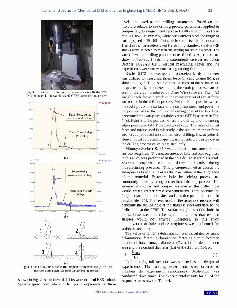
Fig. 3. Thrust force and torque measurements using Kistler 9272
dynamometer during stainless steel-GFRP stacks drilling process
(a)
(b)
(c)
Fig. 4. Graph of (a) thrust force, (b) torque measurement and (c) drill bit
position during stainless steel-GFRP drilling process
shown in Fig. 2. All of these drill bits were made of HSS-cobalt.
Spindle speed, feed rate, and drill point angle each has three
levels and used as the drilling parameters. Based on the
literature related to the drilling process parameters applied in
composites, the range of cutting speed is 40 - 80 m/min and feed
rate is 0.05-0.15 mm/rev, while for stainless steel the range of
cutting speed is 15 - 60 m/min and feed rate is 0.10-0.2 mm/rev.
The drilling parameters used for drilling stainless steel-GFRP
stacks were selected to match the setting for stainless steel. The
varied levels of drilling parameters used in this experiment are
shown in Table 3. The drilling experiments were carried out on
Brother TC22AO CNC vertical machining center and the
experiments were run without using cutting fluid.
Kistler 9272 four-component piezoelectric dynamometer
was utilized to measuring thrust force (Fz) and torque (Mz), as
shown in Fig. 3. The results of measurement of thrust force and
torque using dynamometer during the cutting process can be
seen in the graph displayed by Dyno Wire software. Fig. 4 (a)
and (b) each shows a graph of the measurement of thrust force
and torque in the drilling process. Point 1 is the position where
the tool tip is on the surface of the stainless steel, and point 4 is
the position where the tool tip and cutting edge of the tool have
penetrated the workpiece (stainless steel-GFRP) as seen in Fig.
4 (c). Point 3 is the position where the tool tip and the cutting
edges penetrated GFRP composites already. The value of thrust
force and torque used in this study is the maximum thrust force
and torque produced on stainless steel drilling, i.e., at point 2.
Hence, thrust force and torque measurements are carried out in
the drilling process of stainless steel only.
Mitutoyo Surftest SJ-310 was utilized to measure the hole
surface roughness. The measurement of hole surface roughness
in this study was performed in the hole drilled in stainless steel.
Material properties can be altered incidently during
manufacturing processes. This phenomenon often causes the
emergence of residual stresses that can influence the fatigue life
of the material. Fasteners hole for joining process are
commonly made by using conventional drilling process. The
emerge of notches and rougher surfaces in the drilled hole
would create greater stress concentrations. They become the
fatigue crack initiation sites and a subsequent reduction in
fatigue life [14]. The rivet used in the assembly process will
penetrate the drilled hole at the stainless steel and then to the
drilled hole at the GFRP. The surface roughness of the holes in
the stainless steel must be kept minimum so that residual
stresses would not emerge. Therefore, in this study
minimization of hole surface roughness was performed for
stainless steel only.
The value of GFRP’s delamination was calculated by using
delamination factor. Delamination factor is a ratio between
maximum hole damage diameter (Dmax) in the delamination
area and the nominal diameter (D0) of the drill bit [15], or:
D = Dmax
D0
(1)
In this study, full factorial was selected as the design of
experiments. The running experiments were ordered to
maintain the experiment randomness. Replication was
conducted three times. The experimental results for all of the
responses are shown in Table 4.
International Journal of Mechanical & Mechatronics Engineering IJMME-IJENS Vol:19 No:04 34
191804-3535-IJMME-IJENS © August 2019 IJENS I J E N S
TABLE IV
Result of experiments
No n Vf PA Fz Mz SR D No n Vf PA Fz Mz SR D
1 600 90 140 451.80 5.291 1.986 1.170 43 1500 120 130 355.20 3.261 1.961 1.129
2 2400 120 130 300.70 2.828 1.548 1.109 44 2400 90 118 188.50 1.911 1.352 1.070
3 1500 90 130 284.10 2.317 1.625 1.098 45 2400 60 140 214.40 1.101 1.042 1.073
4 1500 90 118 235.50 1.954 1.451 1.088 46 1500 120 140 430.60 3.157 1.925 1.147
5 1500 60 140 254.50 2.225 1.220 1.095 47 1500 60 130 224.10 1.855 1.342 1.081
6 2400 90 130 243.20 2.149 1.231 1.093 48 600 60 130 296.50 2.853 1.403 1.105
7 600 60 118 232.80 1.812 1.545 1.079 49 600 90 130 362.10 4.064 1.943 1.139
8 600 90 118 302.70 2.855 1.942 1.115 50 2400 90 140 286.60 1.571 1.291 1.099
9 1500 60 118 162.40 1.334 1.262 1.051 51 600 120 140 557.20 5.055 2.490 1.165
10 1500 120 118 290.40 2.571 1.926 1.108 52 600 60 140 339.40 2.444 1.456 1.114
11 1500 90 140 343.00 3.135 1.546 1.124 53 2400 120 140 385.80 2.143 1.635 1.143
12 600 120 118 350.30 3.280 2.595 1.124 54 2400 60 118 109.40 1.551 1.144 1.050
13 600 120 130 433.40 5.067 2.364 1.166 55 600 90 140 451.30 3.681 1.957 1.169
14 2400 60 130 175.50 1.416 1.080 1.054 56 2400 120 130 298.60 2.328 1.554 1.115
15 2400 120 118 250.90 2.195 1.535 1.095 57 1500 90 130 280.00 2.597 1.631 1.096
16 1500 120 130 350.90 3.591 1.935 1.136 58 1500 90 118 234.10 2.824 1.487 1.083
17 2400 90 118 190.80 1.587 1.358 1.068 59 1500 60 140 251.00 1.475 1.192 1.089
18 2400 60 140 209.80 1.597 1.011 1.073 60 2400 90 130 241.40 1.687 1.267 1.086
19 1500 120 140 431.70 4.492 1.986 1.165 61 600 60 118 228.90 3.175 1.523 1.081
20 1500 60 130 225.80 1.631 1.313 1.074 62 600 90 118 305.90 4.482 1.921 1.119
21 600 60 130 293.10 2.743 1.414 1.109 63 1500 60 118 158.60 2.198 1.286 1.055
22 600 90 130 365.60 3.615 1.983 1.136 64 1500 120 118 293.90 3.597 1.910 1.102
23 2400 90 140 289.90 2.481 1.281 1.099 65 1500 90 140 346.70 2.255 1.589 1.129
24 600 120 140 555.90 5.620 2.501 1.189 66 600 120 118 353.90 5.632 2.546 1.143
25 600 60 140 342.10 3.114 1.417 1.123 67 600 120 130 438.60 5.287 2.387 1.158
26 2400 120 140 383.70 4.080 1.605 1.150 68 2400 60 130 176.20 1.320 1.105 1.066
27 2400 60 118 109.20 1.065 1.113 1.050 69 2400 120 118 250.90 2.765 1.598 1.088
28 600 90 140 448.50 3.625 1.935 1.161 70 1500 120 130 351.30 3.297 1.910 1.134
29 2400 120 130 303.40 2.375 1.535 1.111 71 2400 90 118 193.40 1.920 1.343 1.073
30 1500 90 130 279.20 2.545 1.665 1.096 72 2400 60 140 213.20 1.091 1.022 1.080
31 1500 90 118 230.20 2.895 1.423 1.084 73 1500 120 140 434.50 3.145 1.935 1.153
32 1500 60 140 249.50 1.448 1.186 1.088 74 1500 60 130 220.40 1.825 1.356 1.081
33 2400 90 130 240.00 1.678 1.223 1.088 75 600 60 130 294.20 2.812 1.434 1.110
34 600 60 118 234.30 3.187 1.587 1.085 76 600 90 130 367.80 4.092 1.958 1.150
35 600 90 118 307.10 4.414 1.907 1.112 77 2400 90 140 287.10 1.564 1.315 1.101
37 1500 120 118 289.20 3.612 1.953 1.105 78 600 120 140 555.10 5.025 2.521 1.178
38 1500 90 140 348.80 2.212 1.602 1.118 79 600 60 140 344.10 2.400 1.411 1.128
39 600 120 118 355.60 5.666 2.534 1.131 80 2400 120 140 386.80 2.124 1.598 1.151
40 600 120 130 437.20 5.211 2.402 1.159 81 2400 60 118 110.60 1.611 1.148 1.050
41 2400 60 130 171.70 1.311 1.087 1.063
42 2400 120 118 252.80 2.734 1.579 1.093

International Journal of Mechanical & Mechatronics Engineering IJMME-IJENS Vol:19 No:04 35
191804-3535-IJMME-IJENS © August 2019 IJENS I J E N S
IV. OPTIMIZATION PROCESSES
A. BPNN modelling
Input data of BPNN is a process parameters of the drilling,
such as n Vf, and PA. The responses measurement is used as the
output, which is the data of Fz, Mz, SR, and D. In general, the
stages in BPNN are:
• Data pre-processing.
• Modeling the BPNN network architecture and determination
of stopping criteria.
• BPNN training, testing, and validation of data.
1) BPNN modelling
Input and output data should be normalized prior to BPNN
modeling. Normalization of the input and out data is important
to make the interval value of data suitable to the interval value
of activation function that will be used in BPNN modeling.
Therefore, in the pre-processing method various intervals in
input and output data must be modified to a single interval. Data
normalization is a process of converting a data value into a
value of between -1 and 1. Data pre-processing was done by
using a mapminmax function on Matlab R2015.a, and the used
equation is:
pn =2(p−min(p))
(max(p)−min(p))− 1, (2)
where:
p = input and output BPNN data which have various unit and
interval value.
pn = normalized input and output BPNN data which have -1 to
1 interval value and unitless.
Fig. 5. BPNN architecture
Fig. 6. Correlation graphs of BPNN
Fig. 7. Comparison between experimental data and BPNN data prediction

International Journal of Mechanical & Mechatronics Engineering IJMME-IJENS Vol:19 No:04 36
191804-3535-IJMME-IJENS © August 2019 IJENS I J E N S
2) Determination of BPNN network architecture and stopping
criteria
BPNN can produce a precise prediction if using an optimum
BPNN network architecture. BPNN network architecture
consists of the input and output layer with a certain number of
neurons and the hidden layer with a particular number of
neurons. In the input and output layer, the number of neurons
defined by the number of drilling parameters and responses.
Hence, the number of neuron in the input layer and the output
layer are three and four respectively. The number of neurons in
the hidden layer and the number of hidden layers were defined
by conducting the trial and error method to attain the minimum
value of mean square error (MSE).
The trial and error method show that two hidden layers with
13 neurons each are needed and producing 0.0361 MSE value,
which is the minimum MSE. Therefore, the configuration of
BPNN network architecture in this study was 3-13-13-4, as seen
in Fig. 5. In this BPNN model, the hidden layer and output layer
activation functions were tansig and purelin, respectively. The
applied training function was Levenberg-Marquardt. The
values of stopping criteria for BPNN training data, namely
maximum epoch number, performance goal, minimum
performance gradient, and maximum validation failure in
succession are 10000, 0.0001, 0.00001, and 1000.
3) BPNN training, testing, and validation of data
Predicting response values using BPNN method requires
three sets of data for training, testing, and validation. Seventy
percent of data for training and fifteen percent of data each for
testing and validating respectively.
BPNN output or predicted result are in excellent conformity
with the experimental values, i.e., the achieved correlation
coefficient for training, testing, validating, and all data in
succession were 0.97926, 0.94041, 0.95105, and 0.97223 as
shown in Fig. 7. The overall graphical data of BPNN on the
comparison between the predicted and experimental value of all
the combinations upon each response shown in Fig. 6. The
average error between the experimental and predicted was no
more than 10%. This confirms the idea that the prediction on
the responses is not very much different from the experimental
data [16]. A similar method for analyzing the correlations
among the output and target values in term of training, testing,
and all data was also conducted by Kumar and Sait [17] and
Soepangkat et al. [13].
B. Optimization using GA
The general steps of optimization using GA are as follows:
• Definition of the fitness function.
• Determination of GA parameters.
• Optimization using GA and confirmation experiment.
1) Definition of the fitness function
The fitness function is an essential function that used to attain
the optimum value of responses during the drilling process.
Objective function can be used as fitness function directly, or
modified little bit. On the first iteration a number of potential
solutions will be randomly generated, and these potential
solutions will be assessed by utilizing a fitness function [18]. In
this research, those function was developed by combining four
objective functions, where each objective function belonged to
Fz, Mz, SR, and D. Activation function utilized tansig
(hyperbolic tangent sigmoid) transfer function. The objective
function for each response and the activation value of each
neuron in the hidden layer were developed by using the
following equations [19].
𝑂𝑏𝑗𝑙 = (∑ 𝑤𝑘𝑙 . ((2
1+𝑒−2z𝑧𝑘) − 1)13
𝑙=1 ) + 𝑤0𝑙, (3)
𝑧𝑧𝑘 = (∑ 𝑣𝑗𝑘 . ((2
1+𝑒−2𝑧𝑗
) − 1)13𝑘=1 ) + 𝑣0𝑘, (4)
𝑧𝑗 = (∑ (𝑢𝑖𝑗 . 𝑥𝑖)13𝑗=1 ) + 𝑢0𝑗 , (5)
where:
i = number of drilling parameters.
j = number of neurons in first hidden layer.
TABLE V
Lower and upper limit interval of stainless steel-GFRP drilling process
parameters
Drilling Parameters Unit Limit
Lower Upper
Spindle speed (n) rpm 600 2400
Feed rate (Vf) mm/min 60 120
Drill point angle (PA) - 118 140
TABLE VI
Comparison between BPNN-GA prediction and confirmation experiments
Drilling Parameters Fz (N) Mz (Nm)
n Vf PA pred./exp. Error
(%) pred./exp.
Error
(%)
2343 61 118 215.69/208.25 3.45 1.367/1.310 4.17
Drilling Parameters SR (µm) D
n Vf PA pred./exp. Error
(%) pred./exp.
Error
(%)
2343 61 118 1.178/1.126 4.41 1.097/1.087 1.82
(a)
(b)
Fig. 8. Delamination defects of GFRP observed (a) before and (b) after
optimization

International Journal of Mechanical & Mechatronics Engineering IJMME-IJENS Vol:19 No:04 37
191804-3535-IJMME-IJENS © August 2019 IJENS I J E N S
Fig. 9. Resonse graph for (a) thrust force, (b) torque, (c) hole surface roundness, and (d) delamination
k = number of neurons in second hidden layer.
l = number of drilling responses.
𝑂𝑏𝑗𝑙 = objective function, i.e., thrust force, torque, hole surface
roughness, and delamination.
𝑧𝑗 = activation value for each neuron on first hidden layer.
𝑧𝑧𝑘 = activation value for each neuron on second hidden layer.
𝑢𝑖𝑗 = weight value from input layer to first hidden layer.
𝑣𝑗𝑘 = weight value from first hidden layer to second hidden
layer.
𝑤𝑘𝑙 = weight value from second hidden layer to output layer.
𝑢0𝑗 = bias value from the input layer to first hidden layer.
𝑣0𝑘 = bias value from first hidden layer to second hidden layer.
𝑤0𝑙 = bias value from second hidden layer to output layer.
After the four objective function were obtained, they were
combined into a one fitness function and would be minimized
as shown in the following equation:
𝑚𝑖𝑛𝑖𝑚𝑖𝑧𝑒 𝑓(𝑥) = 𝑂𝑏𝑗1 + 𝑂𝑏𝑗2 + 𝑂𝑏𝑗2 + 𝑂𝑏𝑗4 ,, (7)
where:
𝑂𝑏𝑗1 = Objective function of thrust force.
𝑂𝑏𝑗2 = Objective function of torque.
𝑂𝑏𝑗3 = Objective function of hole surface roughness.
𝑂𝑏𝑗4 = Objective function of delamination.
2) Determination of GA parameters
The GA parameters should be determined properly in order
to achieve the optimum value of responses. The names and
values of GA parameters used in the optimization such as
population size, generation size, selection method, crossover
method, crossover probability, mutation method, and mutation
probability in succession are 100, 100, roulette wheel, two
point, 0.8, uniform, and 0.05.
The lower and upper limit values of the parameters of the
stainless steel-GFRP drilling process showed in Table 5.
3) The result of optimization using GA and confirmation experiment
By solving multi-performance optimization utilizing GA
method, the optimum Fz, Mz, SR, and D could be attained by
combining spindle speed of 2343 rpm and feed rate of 61
mm/min with 118º drill point angle. This process parameters
setting is then used as an input to predict the responses values
using BPNN. The comparison between the predicted Fz, Mz,
SR, and D using BPNN and confirmation experiments are
shown in Table 6. The confirmation experiments using
optimum drilling parameter setting are replicated five times,
and the averages value are shown in Table 6. The values of Fz,
Mz, SR, and D from the results of confirmation experiments are
lower than the prediction by BPNN-GA. Table 6 shows that the
errors between the results of BPNN-GA prediction and

International Journal of Mechanical & Mechatronics Engineering IJMME-IJENS Vol:19 No:04 38
191804-3535-IJMME-IJENS © August 2019 IJENS I J E N S
confirmation experiment do not exceed 5% for Fz, Mz, SR, and
D (drilling responses), which mean that BPNN based GA
optimization technique is effective and adequate due to all of
the relative errors are less than or equal to 5%. Therefore, the
minimum values for Fz, Mz, SR, and D could be achieved by
using the parameters of drilling which were obtained by
conducting optimization based on the combination of BPNN
and GA methods. The similar method was also used by
Soepangkat et al. [20] to optimize the tool flank wear, surface
roughness, and metal removal rate in end milling process of
ASSAB XW 42 using cryogenic coolant.
Fig. 8 shows the microscopic delamination photos in hole
exit of GFRP before optimization using spindle speed at 600
rpm, feed rate at 120 mm/min, and 140˚ drill point angle. The
minimum delamination in the hole exit was attained by
combining 118˚ drill point angle, with spindle and feed rate at
2343 rpm and 61 mm/min respectively. The optimum setting
would decrease the delamination as much as 8.4%.
V. EFFECT OF THE DRILLING PROCESS PARAMETERS
The four responses, i.e., thrust force, torque, surface
roughness, and delamination are summarized in Fig. 9. As
shown in Fig. 9 (a), the increasing spindle speed in drilling
stainless steel was found to decrease the thrust force, which is
in accordance with the experimental results of Meral et al. [21],
Neseli [22], and also to what was stated by Armarego [23]. On
the other hand, increasing the feed rate would increase the chip
cross section and hence raising up the thrust force [24]. The feed
rate is the most significant factor affecting the thrust force. The
increase of point angle would increase thrust force slightly,
which is in good agreement to what was stated by Armarego
[23] and also by Stephenson and Agapiou [25].
Fig. 9 (b) shows that torque in drilling stainless steel decrease
with the increase of spindle speed and point angle, but decrease
with the increase of feed rate. Similar to thrust force, an increase
in spindle speed would decrease the torque. This happens
because the high temperatures occurring in the cutting zone
reduce the yield strength of the stainless steel, which is also
stated by Meral et al. [21]. The increase of point angle would
decrease torque slightly, which can also be found in Armarego
[23] and Stephenson and Agapiou [25]. According to Neseli
[22], the cutting speed contributes the most to the torque in
drilling steel.
As can be seen in Fig. 9 (c), the surface roughness value of
stainless steel decreases with increasing cutting speed, and there
would be an increase with increasing feed rate value. This
phenomenon is parallel to the literature which states that the
increase in cutting speed up to a certain point affects the surface
quality positively [26]. The increasing point angle would
decrease surface roughness due to less chip removal area, in the
tool per revolution. This phenomenon was also reported by
Demir [27].
Fig. 9 (d) depicts that hole delamination in GFRP drilling
could be minimized by applying high spindle speed, low feed
rate and low degree of point angle. It can be seen that the
increase of spindle speed would decrease hole exit
delamination. The increase of the spindle speed would decrease
thrust force during the drilling process. Lower thrust force
would produce smaller hole exit delamination. Hence, the
increase of spindle speed would decrease hole exit
delamination. These phenomena are in agreement with
Armarego [23] and Azmi [28].
Fig. 9 (d) also indicates that the decreasing of feed rate would
decrease the hole exit delamination during GFRP drilling
process. The decreasing of feed rate would decrease the thrust
force during the drilling process. Lower thrust force would
decrease the hole exit delamination. Therefore, the decreasing
of feed rate would decrease hole exit delamination. This
phenomenon was also stated by Rochim [29]. Moreover, the
same figure also shows that hole exit delamination increased
with increasing point angle. This result was also mentioned by
Azmi [28] and Kilickap [30].
VI. CONCLUSION
This study introduces an effective multi-performance
optimization technique that combines back propagation neural
network (BPNN) and genetic algorithm (GA) on stainless steel-
GFRP stacks drilling process. The experimental works come up
with the following concluding remarks:
The results of process analysis depict that increasing feeding
speed increases thrust force and delamination considerably,
but increase surface roughness moderately compared to the
increase of spindle speed and point angle. On the other hand,
torque would increase greatly with the increasing of spindle
speed compared to the increase of feeding speed and point
angle. The effect of point angle on the four responses is the
smallest.
BPNN has been utilized to model the responses such as
thrust, torque, surface roughness, and hole exit
delamination. Various BPNN architectures have been
evaluated and 3-13-13-4 configuration (two hidden layer
with thirteen neurons each, three neurons on the input and
four neurons on the output layer) is obtained as the best
architecture. The MSE training of this optimum network
architecture was 0.0361. Trainlm, tansig, and purelin were
the activation functions used on BPNN training, hidden
layer, and output layer subsequently.
BPNN has predicted the minimum thrust force, torque,
surface roughness, and hole exit delamination (Fz, Mz, SR,
and D) successfully after properly trained since the average
error produced are less than 10%.
The minimum thrust force, torque, surface roughness, and
hole exit delamination obtained by utilizing a BPNN based
GA optimization method for the input parameters
investigated. The four responses can be minimized
simultaneously by the usage of high spindle speed of 2343
rpm, low feeding speed of 61 mm/min, and low drill point
angle of 118°.
BPNN based GA optimization method is effective and
acceptable due to all of the relative errors between
prediction and experiments confirmation are not more than
5%.

International Journal of Mechanical & Mechatronics Engineering IJMME-IJENS Vol:19 No:04 39
191804-3535-IJMME-IJENS © August 2019 IJENS I J E N S
ACKNOWLEDGEMENT
The authors would acknowledge the BP PTNBH 2017
research grant from Institut Teknologi Sepuluh Nopember,
Surabaya-Indonesia.
REFERENCES
[1] J. Xu, A. Mkaddem, and M. El Mansori, “Recent advances in drilling
hybrid FRP/Ti composite: A state-of-the-art review,” Composite
Structures, vol. 135. Elsevier Ltd, pp. 316–338, 2016.
[2] J. Xu and M. El, “Experimental study on drilling mechanisms and
strategies of hybrid CFRP / Ti stacks,” Composite Structures, vol. 157,
pp. 461–482, 2016.
[3] M. Ramulu, T. Branson, and D. Kim, “A study on the drilling of
composite and titanium stacks,” Composite Structures, vol. 54, no. 1, pp.
67–77, 2001.
[4] D. Kim and M. Ramulu, “Drilling process optimization for
graphite/bismaleimide-titanium alloy stacks,” Composite Structures,
vol. 63, no. 1, pp. 101–114, 2004.
[5] K. H. Park, A. Beal, D. D. W. Kim, P. Kwon, and J. Lantrip, “Tool wear
in drilling of composite/titanium stacks using carbide and polycrystalline
diamond tools,” Wear, vol. 271, no. 11–12, pp. 2826–2835, 2011.
[6] O. Isbilir and E. Ghassemieh, “Comparative study of tool life and hole
quality in drilling of CFRP/titanium stack using coated carbide drill,”
Machining Science and Technology, vol. 17, no. 3, pp. 380–409, 2013.
[7] Z. Qi, K. Zhang, Y. Li, S. Liu, and H. Cheng, “Critical thrust force
predicting modeling for delamination-free drilling of metal-FRP stacks,”
Composite Structures, vol. 107, pp. 604–609, 2014.
[8] S. Chatterjee, K. Abhishek, S. S. Mahapatra, S. Datta, and R. K. Yadav,
“NSGA-II approach of optimization to study the effects of drilling
parameters in AISI-304 stainless steel,” in Procedia Engineering, 2014,
vol. 97, pp. 78–84.
[9] E. Kilickap and M. Huseyinoglu, “Selection of optimum drilling
parameters on burr height using response surface methodology and
genetic algorithm in drilling of AISI 304 stainless steel,” Materials and
Manufacturing Processes, vol. 25, no. 10, pp. 1068–1076, 2010.
[10] S. R. Karnik, V. Gaitonde, and J. P. Davim, “Integrating Taguchi
principle with genetic algorithm to minimize burr size in drilling of AISI
316L stainless steel using an artificial neural network model,”
Proceedings of the Institution of Mechanical Engineers, Part B: Journal
of Engineering Manufacture, vol. 221, no. 12, pp. 1695–1704, 2007.
[11] N. Mohan, S. Sharma, and R. Bhat, “A Comprehensive Study of Glass
Fibre Reinforced,” International Journal of Mechanical and Production
Engineering Research and Development (IJMPERD), vol. 9, no. 1, pp.
1–10, 2019.
[12] K. Kalita, P. K. Mallick, A. K. Bhoi, and R. K. Ghadai, “Optimizing
drilling induced delamination in GFRP composites using genetic
algorithm& particle swarm optimisation,” Advanced Composites Letters,
vol. 27, no. 1, pp. 1–9, 2018.
[13] B. O. P. Soepangkat, B. Pramujati, M. K. Effendi, R. Norcahyo, and A.
M. Mufarrih, “Multi-objective Optimization in Drilling Kevlar Fiber
Reinforced Polymer Using Grey Fuzzy Analysis and Backpropagation
Neural Network–Genetic Algorithm (BPNN–GA) Approaches,”
International Journal of Precision Engineering and Manufacturing, vol.
20, no. 4, pp. 593–607, 2019.
[14] D. Sun, D. Keys, Y. Jin, S. Malinov, Q. Zhao, and X. Qin, “Hole-making
and its Impact on the Fatigue Response of Ti-6AL-4V Alloy,” Procedia
CIRP, vol. 56, pp. 289–292, 2016.
[15] V. N. Gaitonde, S. R. Karnik, and J. Paulo Davim, “Taguchi multiple-
performance characteristics optimization in drilling of medium density
fibreboard (MDF) to minimize delamination using utility concept,”
Journal of Materials Processing Technology, vol. 196, no. 1–3, pp. 73–
78, 2008.
[16] Y. Rong et al., “Parameters optimization of laser brazing in crimping
butt using Taguchi and BPNN-GA,” Optics and Lasers in Engineering,
vol. 67, pp. 94–104, 2015.
[17] K. V. Kumar and A. N. Sait, “Modelling and optimisation of machining
parameters for composite pipes using artificial neural network and
genetic algorithm,” International Journal on Interactive Design and
Manufacturing, vol. 11, no. 2, pp. 435–443, 2017.
[18] N. Shetty, M. A. Herbert, R. Shetty, D. S. Shetty, and G. S. Vijay, “Soft
computing techniques during drilling of bi-directional carbon fiber
reinforced composite,” Applied Soft Computing Journal, vol. 41, pp.
466–478, 2016.
[19] R. Norcahyo, B. O. P. Soepangkat, and Sutikno, “Multi response
optimization of thrust force and delamination in carbon fiber reinforced
polymer (CFRP) drilling using backpropagation neural network-particle
swarm optimization (BPNN-PSO),” in AIP Conference Proceedings,
2018, vol. 1983.
[20] B. O. P. Soepangkat, R. Norcahyo, D. R. Pamuji, and N. Lusi, “Multi-
objective optimization in end milling process of ASSAB XW-42 tool
steel with cryogenic coolant using grey fuzzy logic and backpropagation
neural network-genetic algorithm (BPNN-GA) approaches,”
International Review of Mechanical Engineering, vol. 12, no. 1, 2018.
[21] G. Meral, M. Sarıkaya, M. Mia, H. Dilipak, U. Şeker, and M. K. Gupta,
“Multi-objective optimization of surface roughness, thrust force, and
torque produced by novel drill geometries using Taguchi-based GRA,”
International Journal of Advanced Manufacturing Technology, pp.
1595–1610, 2018.
[22] S. Neseli, “Optimization of process parameters with minimum thrust
force and torque in drilling operation using taguchi method,” Advances
in Mechanical Engineering, vol. 2014, 2014.
[23] E. J. A. Armarego, Material removal processes : Twist drills and drilling
operations. Melbourne: University of Melbourne, Department of
Mechanical and Manufacturing Engineering, Manufacturing Science
Group, 1996.
[24] A. Taşkesen and K. Kütükde, “Experimental investigation and multi-
objective analysis on drilling of boron carbide reinforced metal matrix
composites using grey relational analysis,” Measurement: Journal of the
International Measurement Confederation, vol. 47, no. 1, pp. 321–330,
2014.
[25] D. Stephenson and J. Agapiou, Metal Cutting Theory and Practice, Third
Edition. CRC PRESS, 2016.
[26] G. Boothroyd and W. A. Knight, Fundamentals of Machining and
Machine Tools, Third. Boca Raton, Florida: CRC PRESS, 2006.
[27] Z. Demir, “An experimental investigation of the effects of point angle on
the high-speed steel drills performance in drilling,” Measurement and
Control (United Kingdom), vol. 51, no. 9–10, pp. 417–430, 2018.
[28] A. I. Azmi, “Machinability Study of Fibre- Reinforced Polymer Matrix
Composites,” Thesis, 2012.
[29] T. Rochim, Metal Cutting. Bandung: ITB, 2007.
[30] E. Kilickap, “Investigation into the effect of drilling parameters on
delamination in drilling GFRP,” Journal of Reinforced Plastics and
Composites, vol. 29, no. 23, pp. 3498–3503, 2010.


![Human Face Recognition Using PCA with BPNN · Block diagram of complete process of PCA & BPNN face recognition system [12] As shown in this above block diagram I had described about](https://static.fdocuments.us/doc/165x107/5f6753df354370019f056e91/human-face-recognition-using-pca-with-bpnn-block-diagram-of-complete-process-of.jpg)