Application Note - Web Server Noelnoel.feld.cvut.cz/hw/philips/acrobat/8196.pdf · Application Note...
24
Application Note I C s f o r M o t o r C o n t r o l TDA5142 output driver stages for supply voltages up to 30 V Report No: EIE/AN93013 R. Galema Product Concept & Application Laboratory Eindhoven, the Netherlands. Keywords Motor Control TDA5142 Date : 27 June 1995 Pages: 20
Transcript of Application Note - Web Server Noelnoel.feld.cvut.cz/hw/philips/acrobat/8196.pdf · Application Note...

Application Note
I C s f o r M o t o r C o n t r o l
TDA5142 output driver stages for supplyvoltages up to 30 V
Report No: EIE/AN93013
R. Galema
Product Concept & Application Laboratory Eindhoven, the Netherlands.
KeywordsMotor Control
TDA5142
Date : 27 June 1995Pages: 20

Summary:
The Motor Control ICs of the TDA514x series can handle supply voltages up to 18 volts. It is withthese ICs not possible to drive directly brushless DC-motors that need a supply voltage higher than18 volts.The TDA5142 has external driver stages. In this paper a circuit diagram has been described,including some component calculations, in which the TDA5142 Motor Control IC is used withexternal driver stages for voltages higher than 18 volts.The described circuit is built on a pc-board and this pc-board is meant to be used as an evaluationboard for motor control in industrial applications for voltages up to 30 volts (24 volts ± 25%). The circuit has been designed in such a way that it can be adapted for use at supply voltages lowerthan 18 volts. This can be done by leaving out some components and inserting some wire bridges. The circuit contains an op-amp controlled current limiter as well.
Philips Semiconductors Application Note EIE/AN93013

- 1 -
Table of Contents:
1. Introduction . . . . . . . . . . . . . . . . . . . . . . . . . . . . . . . . . . . . . . . . . . . . . . . . . . . . 2
2. Circuit description . . . . . . . . . . . . . . . . . . . . . . . . . . . . . . . . . . . . . . . . . . . . . . . . 3
2.1 Vmot control adaptation . . . . . . . . . . . . . . . . . . . . . . . . . . . . . . . . . . . . . . . 6
2.2 Output stage adaptation . . . . . . . . . . . . . . . . . . . . . . . . . . . . . . . . . . . . . . 8
2.2.1 MOSFET output stages. . . . . . . . . . . . . . . . . . . . . . . . . . . . . . . . . 8
2.2.2 Bipolar output stages. . . . . . . . . . . . . . . . . . . . . . . . . . . . . . . . . . . 11
2.3 Comparator input adaptation. . . . . . . . . . . . . . . . . . . . . . . . . . . . . . . . . . . . 15
3. Current Limiter. . . . . . . . . . . . . . . . . . . . . . . . . . . . . . . . . . . . . . . . . . . . . . . . . . 17
4. Parts list . . . . . . . . . . . . . . . . . . . . . . . . . . . . . . . . . . . . . . . . . . . . . . . . . . . . . . 19
Philips Semiconductors Application Note EIE/AN93013

- 2 -
1. Introduction
The TDA5142 motor control IC has been designed for motor control applications for supplyvoltages up to 18 volts and for use with external driver stages.
For motor voltages greater than 18 V some interface circuitry has to be added to prevent that therated voltages for the IC are exceeded.The output stages can be built-up with power MOSFETS or bipolar transistors. The pcb lay-out is made such that the output stages can be provided with MOSFETS or bipolartransistors as well.
The driver outputs NA, PA, NB, PB, NC and PC, the OTA output AMP-out and the inputs Vmot,Comp-A, Comp-B, Comp-C, MOT0 and AMPIN+ can not withstand voltages higher than 18 volts.
The component calculations have been carried-out for a Vsupply up to 30 V. This is, however, not anabsolute limit. With other components values the circuit can also be used for higher voltages.
In this report only the calculation of the components of the output driver section has been given.See the specification of the TDA5142 for the calculation of the timing capacitors C5 up to C8.
Philips Semiconductors Application Note EIE/AN93013

- 3 -
2. Circuit description
In figure 1 a circuit has been depicted for supply voltages up till 18 volts.
In this circuit we distinguish the following parts:
1. the Vmot control part with T10, R42, R30, R39, R40, C1, C2 and the OTA (inside toTDA5142) with AMPIN-, AMPIN+ and the AMPOUT.
2. the output drivers (T1 - T6) with fly-back diodes (D1 - D6) and the connections to thecomparators inputs via the resistors R27 - R29 and R10.
3. the current limiter circuit with the op-amp IC2A, the current sense resistor R17A and B,the transistor T10 to limit the current of T10 and some additional components to set thecurrent limit.
In this diagram one can see that the output driver stages, made with an N-channel and P-channelMOSFET pair, have been connected to the outputs of the TDA5142 via series resistor of 47 Ω.This resistor is necessary to prevent HF oscillations in the output power MOSFETS. Theseresistors must be mounted as close as possible to the MOSFET.However, when the outputs stages are made with bipolar transistors these series resistors are usedto determine the base current for the bipolar transistors. If a bipolar output stage is used one can consider an output stage with an NPN/PNP transistor pairor with an NPN/PNP darlington transistor pair. This will be discussed later on in this report.
In figure 2 a circuit has been depicted with the interface circuit to make the system suitable forvoltages higher than 18 volts.
In the next paragraphs the different interfaces will be discussed together with some componentcalculations.
Philips Semiconductors Application Note EIE/AN93013

- 4 -
Figure 1
Philips Semiconductors Application Note EIE/AN93013

- 5 -
Figure 2
Philips Semiconductors Application Note EIE/AN93013

- 6 -
2.1 Vmot control adaptation
The motor speed can be controlled with the voltage Vmot. In this system the control of Vmot is accomplished by using the on-chip OTA. The voltage Vmot isfed back via R39 and R40 to the AMPIN+ input of the OTA and AMPOUT drives a bipolarpower transistor or a power P-channel MOSFET T10. The voltage Vin, connected to the AMPIN-input, controls the voltage Vmot. The relation between Vin and Vmot is as follows:
The supply for the OTA is retrieved from VP. The maximum input voltage on the AMPIN inputs is
(1)
VP - 1.7 V, so, for a good control of Vmot, the voltage on these inputs may not exceed this value.The resistors R39 and R40 have to be determined in such a way that the required control range ofVin is covered and that the input voltage on the AMPIN inputs is lower than VP - 1.7 V at thehighest possible value of Vmot.
The output voltage of the OTA may not exceed 18 V. For Vmot ≥ 18 V the output voltage of theOTA must be limited to 18 V. To achieve this the transistor T13 has been inserted. The maximumbase voltage of T13 is determined by a zener diode (D8) and limits in this way the voltage on theAMPOUT pin. To have some margin, due to zener voltage tolerances, a zener diode of 15 V hasbeen chosen. The base voltage VbT13 is determined by Vsupply - R33 x IbT13 and follows the Vsupply until it isclamped by the zener diode D8.
Take for the zener diode a current of about 5 mA at Vsupply is 30 V.
Take R41 = 2.7 kΩ.
(2)
The control circuit for Vmot can operate with both a bipolar power transistor or a P-channel powerMOSFET. The evaluation board will be equipped with a BD438 or equivalent.
If a bipolar transistor is used the collector current IcT13 is mainly determined by the hfe of T10 andthe collector current of T10. With an average collector current for T10 of 1 A and an hfe for T10 of 50 this results in a basecurrent for T10 of 20 mA. This means, with an hfe of 50 for T13, a base current for T13 of 0.4mA. The current through R41 is about 5 mA, so there is enough current to bias the zener diode D8and to supply the base current for T13.
Philips Semiconductors Application Note EIE/AN93013

- 7 -
The base current for T10 of 20 mA, flowing through T13 into the TDA5142, may cause excessiveheat dissipation in the transistor T13 and the TDA5142. The resistor R33 (470 Ω) has beeninserted in the emitter line of T13 to limit the dissipation in the TDA5142 and transistor T13. Thisresistor is only necessary in case for T10 a bipolar transistor is used.When for T10 a MOSFET is used the collector current IcT13 is determined by R1.With the MOSFET the max. collector current of T13 is:
R42 has been determined experimentally and with this resistor value a good control has been
(3)
obtained.The collector current IcT13 is, in case a MOSFET is used, lower than for the bipolar transistor. Thismeans that components as determined for the bipolar transistor can also be used when a MOSFETis used. The resistor R30 and capacitor C2 are needed for frequency stability of the circuit.
Note:
Because transistor T10 can dissipate much heat, room has been saved on the evaluation board toprovide transistor T10 with a heat sink.
Philips Semiconductors Application Note EIE/AN93013

- 8 -
2.2 Output stage adaptation
In this chapter the output stages are discussed. Because for the output stages both powerMOSFETS and bipolar transistors can be used the component calculations have been carried-outfor both types of output stages.
2.2.1 MOSFET output stages.
In figure 3 one of the three output stages of TDA5142 has been depicted together with an externaloutput stage with MOSFET transistors for Vmot ≤ 18 V.
Figure 3
In this figure we see that the output voltage of the Vmot controller is connected to the Vmot input ofthe TDA5142 and to the common source line of P-channel MOSFETS.
Philips Semiconductors Application Note EIE/AN93013

- 9 -
Figure 4
In figure 4 thecircuit is given forVmot ≥ 18 V. Herewe see that theconnectionbetween thecommon sourceline has beeninterrupted andthat an extratransistor has beenconnected betweenthe TDA5142output Px and thegate of the P-channel MOSFET. With this interface the voltage Vmotor on the common source linecan now be greater than 18 V. The voltage on the Vmot input of the TDA5142 may not exceed 18 V and therefore the Vmot inputhas been connected to an auxiliary voltage source VA, that has a voltage lower than 18 V.
The base current for the interface transistor in series with the gate of the P-channel MOSFET isretrieved, via a resistor, from the voltage source VA. The resistors Rp and Rn are needed, as described earlier, to suppress HF oscillations. The circuit offigure 4 has been implemented into the overall diagram as has been given in figure 2.
For the calculation of the components we refer to the reference numbers as mentioned in figure 2.
The auxiliary voltage source VA has been built-up with transistor T11, zener diode D8 and resistorR41 , the same reference as has been used for transistor T13. The current to be supplied by this voltage source is determined by the current that flows into thegate drive circuitry of the MOSFETS. The output voltage VPA of the TDA5142 switches between VA and GND.
For the interface transistor T9 a BC547 type transistor has been chosen, because the collectorcurrent is low, the switching speed is not very critical and this transistor can withstand a collectorvoltage of at least 50 V.Transistor T9 is switched in the emitter line and is conducting when TDA5142 output is at GNDlevel. The max. collector current is:
Philips Semiconductors Application Note EIE/AN93013

- 10 -
For R3 a value of 2.7 kΩ has been chosen, that gives with a general purpose P-channel MOSFET
(4)
a turn-off time of about 5 µs. If a faster turn-off time is required a lower value for R3 has to bechosen. The resistor R6, to prevent HF oscillations, has a value of 47 Ω and this value has beendetermined experimentally.
To determine the maximum value of IcT9 the voltages VceT9 and VPAmin are considered to be zero and Vmotor = 30 V
The base drive for T9 is determined by R26 and the voltage VA.
(5)
The auxiliary voltage source VA has, as already has been mentioned, been built-up with transistorT11, zener diode D9 and resistor R41. The diode has an initial tolerance of ± 5%. So, the minimum value of VA = 0.95 x 15 - VbeT11 ≈ 13.5 V.The auxiliary voltage source VA has to supply the collector and the base currents for T9, T8 andT7 and the drive current for the output stages of the TDA5142. The currents through T9, T8 and T7 do not flow simultaneously. Only one of the three transistorsis conducting at a time, so the maximum current to be supplied by the transistor T11 is the sum ofthe base and collector current of T9 or T8 or T7.
When the transistor T9 turns-on the collector current of T9 is as follows:
with hfeT9 = 50,
(6)
Choose R26 = 56 kΩ
(7)
(8)
Philips Semiconductors Application Note EIE/AN93013

- 11 -
The current to supply the output drivers inside the TDA5142 has not been specified, but assumethat this current is about equal to currents through the other transistors.Let us assume a total current of 20 mA to be supplied by T11, this means with an hfe for T11 of50 a base current of about 0.4 mA. The current through the zener diode D8 is about 5 mA and this current is large enough to supplythe base current of 0.4 mA for T11 as well.
Philips Semiconductors Application Note EIE/AN93013

- 12 -
2.2.2 Bipolar output stages.
When bipolar output stages are used the component values have to be adapted and somecomponents have to be added. In the output stages both single transistors or darlington transistorcan be used.For bipolar transistors base current has to be supplied. The amount of base current to be suppliedis dependent on the magnitude of the collector (motor) current. The motor current is high as longas the motor is not running and decreases during the start-up. To assure that the conducting output transistors are well saturated the base drive for the transistors must be based upon the highest output collector current. Assume that at a collector current of about 1 A the ratio between the collector current and the basefor a single transistor of 25 and for a darlington transistor of 250.This means for a single transistor a minimum base current of at least 40 mA and for a darlington abase current of only 4 mA. From this we see that for the single transistor the fairly high base current has to be supplied andthat this current always flows, regardless of the magnitude of the collector current. A singletransistor, however , has a lower saturation voltage than a darlington transistor.Despite of the lower saturation voltage of a single transistor (typ. 0.5 V) with respect to thedarlington transistor (typ. 1.2V) the darlington has a higher efficiency. For higher values of Vmotor
the difference between the saturation voltages of both types of transistors is negligible. Consideringall this the darlington transistor has been chosen as output driver.
The circuit for the bipolar output stages needs some adaptations with respect to MOSFET solution.The circuit for one bipolar output stage has been depicted in figure 5.
Figure 5
This output stage replaces the output stagewith MOSFETS as depicted in figure 2. Compared to MOSFET output stages in figure2 we see two extra resistors, R20 and R17.With these resistors a better switch-off of T9and T6 is ensured. When these resistors are left out the switch-offdelay between VPA or VNA and the output willbe about 10 µs in stead of 5 µs.The resistor R20 has to be determined in sucha way that the base emitter breakdown voltage(max. 5 V) of T9 is not exceeded when T9 isin cut-off. When T9 is in cut-off state the base emittervoltage of T9 must be lower than 5 V. This maximum voltage is determined by R20.
Philips Semiconductors Application Note EIE/AN93013

- 13 -
Take R20 = 150 kΩ. The calculation applies for R39 and R40.
(9)
The base current for the PNP darlington transistor is mainly determined by Vmotor and the basecurrent for the NPN darlington by the auxiliary voltage VA.For this application a base current IbDAR for both darlington transistors is assumed of about 4 mA.
Take R6 = 5.6 kΩ.
(10)
(11)
(12)
The same applies for R5 and R4.
With a minimum value of VA = 13.5 V and with IR17 = IR3 = 0.74 mA, we can calculate for R7:
Take R25 = 2.2 kΩ.
(13)
The same applies for R23 and R21.
For R26 (56 kΩ) the same value has been taken as has been calculated for the MOSFET outputstages.
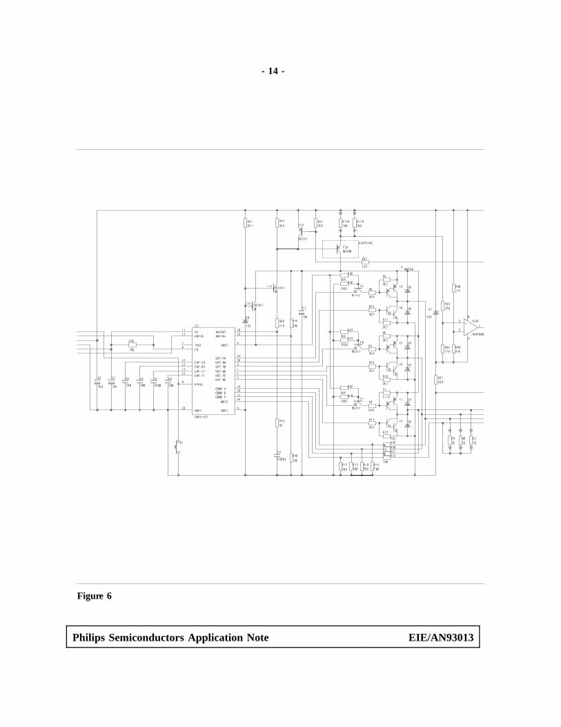
In figure 6 has been depicted the circuit diagram of a system with output darlington transistors andin figure 7 a drawing of the pc-board. A complete circuit diagram with MOSFET output drivers can be derived from figure 2
Philips Semiconductors Application Note EIE/AN93013
- 14 -
Figure 6
Philips Semiconductors Application Note EIE/AN93013

- 15 -
Philips Semiconductors Application Note EIE/AN93013

- 16 -
2.3 Comparator input adaptation.
For detection of the zero-crossings of the motor back-EMF the motor windings and the star pointof the motor are connected via the series resistors R10 and R27 - R29 to the comparator inputs ofthe TDA5142. These resistors are needed for current limiting and protection in case of shortovervoltages on the comparator inputs. The value of these resistors is not critical and have beendetermined experimentally. This means R29 = R28 = R27 = 1 kΩ and R10 = 330 Ω. With thischoice a good input current balancing is achieved. The supply for the comparators is retrieved from Vmot. So, the maximum comparator input voltageis related to the voltage on the Vmot input of the TDA5142. As described in the previous chapterthis pin has been connected to the auxiliary voltage VA. According to the specification the comparator input voltage may exceed the voltage VA by 0.5 V. The means that the maximum value of the comparator input voltage must smaller than theminimum value of VA + 0.5 V.
When a motor is used without an external available star point connection an artificial symmetry
(14)
point must be created for connection to the MOT0 pin of the TDA5142. This can be done byconnecting the MOT0 input via three 1 kΩ resistors to the motor stator windings (R9, R8, R7 infigure 1).In a 30 V system the comparator input voltages must be limited to maximum 14.15 volts. This canbe achieved with the voltage divider resistor R11 for the MOT0 input and with, R14, R13 and R12for the Comp-A, B and C inputs.
For a maximum motor voltage of 30 V and with R27, R28 and R29 = 1 kΩ the value for theresistors R12, R13 and R14 can be determined as follows:
Take, to have some margin, R12 = R13 = R14 = 0.82 kΩ
(15)
For the calculation of R10 and R11 two possibilities have to be distinguished: with or without anartificial star point.In case of an artificial star point also the equivalent resistance of the star point connection must betaken into account. When for these star point resistors a value of 1 kΩ is chosen, then the equivalent resistance isequal to the parallel resistance of the three resistors R7, R8 and R9, thus Req = 1000/3 = 333 Ω.
For a motor with a star point connection the ratio between R10 and R11 must equal to the ratio
Philips Semiconductors Application Note EIE/AN93013

- 17 -
between R27 and R12.
For a motor with artificial star point the resistor R10 has to be determined in such a way that theequivalent star point resistance Req (333 Ω) is included as well.In the calculation above the relation between R12 and R27 has been determined:
R12 = 0.82 x R27,
The same relation applies for R11 and R10, so: R11 = 0.82 x R10 = 270 , with star point
R11= 0.82 x (R10 + 333), with artificial star point.
Determine for R10 such a value from the E24 resistor range, that for R11 a resistor value from theE24 range can be found as well.
When R10 = 240 Ω, then R11 = 0.82 x (240 + 333) = 470 Ω
In figure 2 these resistor have been indicated as TBD (to be determined).
Philips Semiconductors Application Note EIE/AN93013

- 18 -
3. Current Limiter.
In figure 1 the circuit of an op-amp controlled current limiter has been given. This current limiterhas been built-up with the op-amp IC2A, the transistor T11, the resistors R34, R17A/B R35 up toR37 and R43, the zener diode D7 and the decoupling capacitor C3 and C9.The resistor R17A/B is the current sense resistor and the voltage drop Vcs over this resistor iscompared with reference voltage connected pin 3 of the op-amp. The output of the op-amp drivesthe transistor T12. The op-amp used for this circuit (LM358A) can not withstand supply voltages greater than 32 V.To obtain a general circuit that can be used for supply voltages greater than 32 V as well, thecurrent limiter circuit has been referenced to the positive supply voltage Vsupply. The supply voltagefor the op-amp is determined by the zener diode voltage VD7. The op-amp cannot operate with input voltages that are close to the positive supply rail of the op-amp and therefore the input voltages have to be shifted to a level of at least 2 V below the supplyvoltage. The DC-voltage shift is determined by the op-amp supply voltage (VD7) and the voltage dividerR38 and R35 for the V- input and by R43 and R36 for the V+ input. When a supply voltage of 30 volts is used for D7 a zener diode BZX79C12 (12 V) can be choosen. The diode voltage may vary according to the specification @ 25 °Cbetween 11.4 and 12.7 V. To obtain a minimum required DC voltage shift of 2 V the resistor then:
When R43 = 10 kΩ, then R36 = 47 kΩ.
(16)
The current through D7 is determined by resistor R31. For this resistor a value of 1.8 kΩ ischosen.At a lower supply voltage Vs, i.e. 12 volt, for the zener diode D7 a lower voltage must be taken.In that case the resistors the resistors R35 and R36 have to be adapted as well.
The resistors R34 and R37 determine the base current for transistor T12. This transistor has to cut-off the base current of T10 in case the current limiter becomes active. The relation between R34and R37 has to be made such that T12 is switched-off when the output voltage of the op-amp is atits high level (≈ Vsupply -2 V). This means that R16 ≈ 7 x R3. When for R24 a value of 2.2 kΩ ischosen, then R37 = 15 kΩ. With these resistor values a base current for T12 is obtained of about0.33 mA at VD7 = 11.4 V, that can give a enough collector current for T12 to limit the currentthrough transistor T10.The voltages on the V- and V+ input of the op-amp at a typ. zener diode voltage of 12 V can becalculated as follows:
Philips Semiconductors Application Note EIE/AN93013
- 19 -
With V- = V+ and R35 = R36 the following equation for Vcs can be derived:
(17)
(18)
With the increase of the motor current the voltage on the V+ input becomes more negative with
(19)
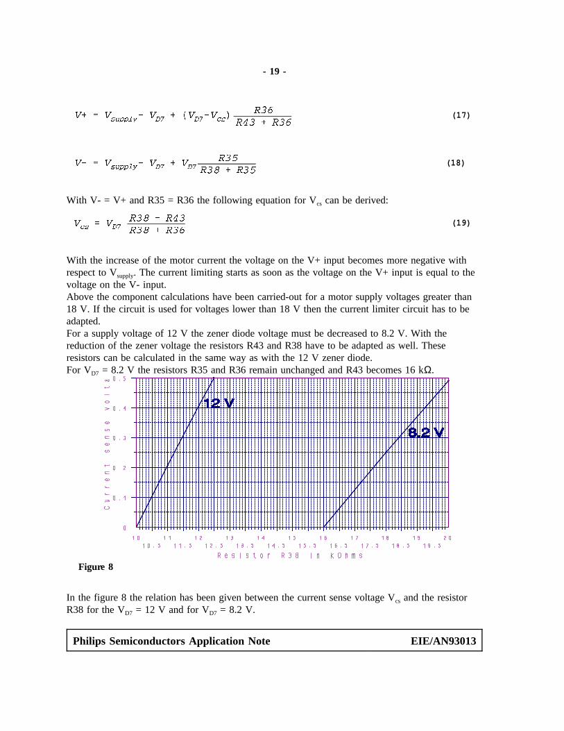
respect to Vsupply. The current limiting starts as soon as the voltage on the V+ input is equal to thevoltage on the V- input.Above the component calculations have been carried-out for a motor supply voltages greater than18 V. If the circuit is used for voltages lower than 18 V then the current limiter circuit has to beadapted. For a supply voltage of 12 V the zener diode voltage must be decreased to 8.2 V. With thereduction of the zener voltage the resistors R43 and R38 have to be adapted as well. Theseresistors can be calculated in the same way as with the 12 V zener diode.For VD7 = 8.2 V the resistors R35 and R36 remain unchanged and R43 becomes 16 kΩ.
In the figure 8 the relation has been given between the current sense voltage Vcs and the resistor
Figure 8
R38 for the VD7 = 12 V and for VD7 = 8.2 V.
Philips Semiconductors Application Note EIE/AN93013

- 20 -
For a certain motor control system has to be determined, what maximum current sense voltage Vcs
can be allowed. With this Vcs and the current limiting value the resistor R17 can be determined.
The pc-board has been designed such that for R17 two resistors can be used in parallel. Theresistor R38 will be mounted on solder pins so that this resistor can easily be changed into othervalues.
Philips Semiconductors Application Note EIE/AN93013

- 21 -
4. Parts list
Below the parts list of both the circuit of figure 6 for as well the MOSFET and the darlingtontransistor output stage is given.
MOSFET outputs Darlington transistor outputs
Item Value Value
C1, C3, C4, C10 10 µF 10 µFC2, C7 0.22 µF 0.22 µFC5, C6 0.018 µF 0.018 µFC8 0.01 µF 0.01 µFC9 0.1 µF 0.1 µF
R1 - R3 2.7 kΩ 2.7 kΩR4 - R6 47 Ω 5.6 kΩR7 - R9 1 kΩ 1 kΩR10 - R14 TBD TBDR15 - R17 2.7 kΩR18 - R20 150 kΩR21, R23, R25 47 Ω 2.2 kΩR22, R24, R26 56 kΩ 56 kΩR27 - R29 1 kΩ 1 kΩR30 22 Ω 22 ΩR31 1.8 kΩ 1.8 kΩR32 10 kΩ 10 kΩR34 2.2 kΩ 2.2 kΩR35, R36 47 kΩ 47 kΩR37 15 kΩ 15 kΩR38 (D7 = BZX79C12) 11 kΩ 11 kΩR38 (D7 = BZX79C8V2) 16 kΩ 16 kΩR39 39 kΩ 39 kΩR40 10 kΩ 10 kΩR41 2.7 kΩ 2.7 kΩR42 5.6 kΩ 5.6 kΩR43 (D7 = BZX79C12 10 kΩ 10 kΩR43 (D7 = BZX79C8V2) 16 kΩ 16 kΩ
Philips Semiconductors Application Note EIE/AN93013

- 22 -
MOSFET outputs Darlington transistoroutputs
Item Value Value
D1 - D6 BYV10-40 BYV10-40D7 BZX79 C12 BZX79 C12D7 BZX79 C8V2 BZX79 C8V2D8 BZX79 C15 BZX79 C15
T1, T2, T3 BD680 BD680T4, T5, T6 BD679 BD679T10 BD438 BD438T12 BC557 BC557T7, T8, T9, T11, T13 BC547 BC547
Philips Semiconductors Application Note EIE/AN93013