APPLICATION NOTE VA-09-1-4files.4safe.fi/viola_systems/m2m_gw/VA-09-1-4_Configuration_guide.pdf ·...
80
© 2010 VIOLA SYSTEMS LTD. WWW.VIOLASYSTEMS.COM VA-09-1-4_CONFIGURATION_GUIDE.PDF APPLICATION NOTE VA-09-1-4 CONFIGURING M2M GATEWAY WITH ARCTIC GPRS/EDGE ROUTER/GATEWAY Version history: 4.0 Clarification on connection parameters 3.0 Minor corrections 2.0 Minor corrections 1.0 Released for review Date: Jun-03-2010 Version: 4.0 Author: LaH Viola Systems Ltd. tel +358-(0)201-226 226 Lemminkäisenkatu 14-18 A fax +358-(0)201-226 220 FIN-20520, Turku e-mail [email protected] Finland
Transcript of APPLICATION NOTE VA-09-1-4files.4safe.fi/viola_systems/m2m_gw/VA-09-1-4_Configuration_guide.pdf ·...

© 2010 VIOLA SYSTEMS LTD. WWW.VIOLASYSTEMS.COM VA-09-1-4_CONFIGURATION_GUIDE.PDF
APPLICATION NOTE VA-09-1-4
CONFIGURING M2M GATEWAY WITH ARCTIC GPRS/EDGE ROUTER/GATEWAY
Version history:
4.0 Clarification on connection parameters 3.0 Minor corrections 2.0 Minor corrections 1.0 Released for review
Date: Jun-03-2010 Version: 4.0 Author: LaH
Viola Systems Ltd. tel +358-(0)201-226 226 Lemminkäisenkatu 14-18 A fax +358-(0)201-226 220 FIN-20520, Turku e-mail [email protected] Finland

2 / 80
Copyright and Trademarks Copyright 2009, Viola Systems Ltd. All rights to this document are owned solely by Viola Systems Ltd. All rights reserved. No part of this document may be transmitted or reproduced in any form or by any means without a prior written permission from Viola Systems. Ethernet™ is a trademark of Xerox Corporation. Windows™, Windows XP™ and Internet Explorer™ are trademarks of Microsoft Corporation. Netscape™ is a trademark of Netscape Communications Corporation. Mozilla® and Firefox® are registered trademarks of Mozilla Foundation. Linux™ is a trademark of Linus Torvalds. Cisco® is a registered trademark of Cisco Systems Corporation. All other product names mentioned in this document are the property of their respective owners, whose rights regarding the trademarks are acknowledged. Disclaimer Viola Systems reserves the right to change the technical specifications or functions of its products or to discontinue the manufacture of any of its products or to discontinue the support of any of its products without any written announcement and urges its customers to ensure that the information at their disposal is valid. Viola software and programs are delivered “as is”. The manufacturer does not grant any kind of warranty including guarantees on suitability and applicability to a certain application. Under no circumstance is the manufacturer or the developer of a program responsible for any damage possibly caused by the use of a program. The names of the programs as well as all copyrights relating to the programs are the sole property of Viola Systems. Any transfer, licensing to a third party, leasing, renting, transportation, copying, editing, translating, modifying into another programming language or reverse engineering for any intent is forbidden without the written consent of Viola Systems. Viola Systems has attempted to verify that the information in this document is correct with regard to the state of products and software on the publication date of the document. We assume no responsibility for possible errors which may appear in this document. Information in this document may change without prior notice from Viola Systems.

3 / 80
Table of contents
1. GENERAL ..............................................................................................................................................................4 2. PRE-REQUISITES ...............................................................................................................................................4 3. CAUTION ...............................................................................................................................................................5 4. INSTALLATION WORKFLOW......................................................................................................................5 5. CHOOSING A CORRECT PRODUCT FOR THE SOLUTION ..............................................................8 6. CHOOSING THE TYPE OF THE VPN........................................................................................................10 7. IP PLANNING .....................................................................................................................................................10 8. BEFORE STARTING ........................................................................................................................................13 9. TOOLS NEEDED FOR INITIAL SETUP.....................................................................................................14 10. CONNECTING AND CABLING THE UNITS..........................................................................................15 11. CABLING ...........................................................................................................................................................15 12. CONFIGURING THE INSTALLATION ENVIRONMENT.................................................................18 13. CONFIGURING THE M2M GATEWAY ..................................................................................................21 14. CONFIGURING THE ARCTIC....................................................................................................................39 15. CONNECTING A SERIAL DEVICE...........................................................................................................61 16. TESTING THE SOLUTION ..........................................................................................................................64 17. APPENDIX A: IP V.4 ADDRESSING AND NETWORKING...............................................................68 18. APPENDIX B: CONNECTION ESTABLISHMENT...............................................................................71 19. APPENDIX C: ACRONYMS AND ABBREVIATIONS .........................................................................72 20. APPENDIX D: VIOLA SYSTEMS’ DEVICE SPECIFIC INFO...........................................................73 21. APPENDIX E: TROUBLESHOOTING......................................................................................................74 22. APPENDIX F: FREQUENTLY ASKED QUESTIONS...........................................................................76 23. APPENDIX G: REFERENCES .....................................................................................................................79

4 / 80
1. General
1.1. Purpose
This document addresses to challenges encountered within the initial configuration of Viola M2M Gateway, Viola Systems Product Code 2500 (later on abbreviated as M2M GW) and Viola Arctic devices with Product Codes 22XX, operating in 2G cellular network (later on abbreviated as Arctic). Because the IP addressing is case specific, this document uses some examples for demonstrating on how the IP addressing and routing would be configured. 1.2. Summary
It has been found that there is a need for a document that describes the initial setup of M2M GW and Arctic in order to build up an end-to-end connection between each others. This document answers to such a need. Furthermore, this document provides supplementary information to M2M GW's and Arctic's user’s manuals. Large amount of data in this document has been gathered based on answers to frequently asked questions from Viola Systems Technical Support. 1.3. Target audience
The target audience for this document is: • Field engineers • Sales partners • Customers' technical personnel
1.4. Conventions
The following conventions are used throughout this document:
• The menu items in graphical user interfaces are denoted as bolded italic font and the sequence of mouse clicks, while configuring the devices in menus is separated with an arrow. Example: “Click Tools System log”.
• The console output is printed with courier font and user input is printed with bold courier font. Example: [viola-adm@m2mgw ~]# date Tue Jun 01 13:05:00 CET 2010
• References to certain parts of this document and figure/table captions are denoted with italic font.
• The acronyms and abbreviations may be used without opening the terms, see Appendix E: Acronyms and abbreviations for reference.
• The usernames and passwords are denoted with courier font. • Parameter-value pairs are denoted with courier font. • Important notes are colored red. • The placeholders for actual values are written between “<” and “>” mark.
For example, the <IP_address> would mean a place to write the actual IP address.
2. Pre-requisites
• It is assumed that the reader of this document has a basic knowledge of Linux and Windows systems, IP networking, serial-connected devices and computers in general.
• The password for the default user viola-adm is known (see the M2M GW's quick start guide for the details).
• The M2M GW's and Arctic's user's manuals and quick start guides are available, while performing the initial setup.
5 / 80
3. Caution
The initial setup of the devices should be done in one centralized location; performing the initial setup in a geographically distributed system may cause unnecessary remote site visits. While configuring the firewall in M2M GW and Arctic, it is possible to lock oneself out of the system. Therefore, in the initial setup phase, it is a good practice to test the console login procedure for both devices. See page 64, chapter 16.1 Testing the console login for more information.
4. Installation workflow
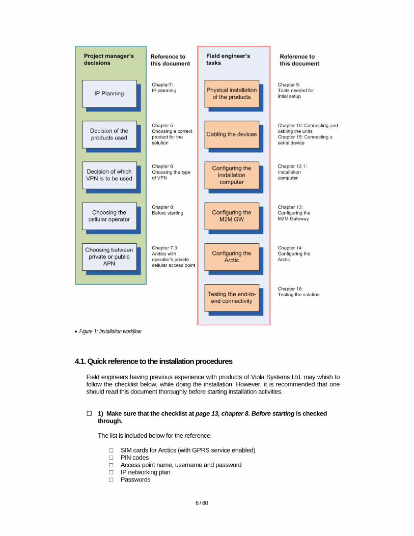
The recommended workflow is seen in Figure 1: Installation workflow. The cross-reference to chapters in this document is written next to the task box. The work flow has been separated into two parts:
• The procedures for planning and decision making • The actual installation procedures
6 / 80
• Figure 1: Installation workflow
4.1. Quick reference to the installation procedures
Field engineers having previous experience with products of Viola Systems Ltd. may whish to follow the checklist below, while doing the installation. However, it is recommended that one should read this document thoroughly before starting installation activities.
1) Make sure that the checklist at page 13, chapter 8. Before starting is checked through. The list is included below for the reference:
□ SIM cards for Arctics (with GPRS service enabled) □ PIN codes □ Access point name, username and password □ IP networking plan □ Passwords

7 / 80
□ IT department for assistance, if present □ Manuals for every device related to the installation □ Cables; network, power, serial, etc. □ Antennas for Arctics, external antennas and antenna cables, if needed □ Power supplies and cables for each device □ DIN rail mounting kits, if needed □ A computer for installation, a laptop with Windows XP recommended
2) Gather the arrived equipment into one central place Gather the Arctics and M2M GW to a central place for testing. If there are serial connected devices on the field, bring one at central site as well, if possible.
3) Connect the cables Create a test installation environment to the central place by connecting the cables for M2M GW and Arctic. Several Arctics can be configured in the test environment before proceeding to the field installation. Refer to the page 15, chapter 10, Connecting and cabling the units for details.
4) Configure the M2M GW and Arctic Configure the M2M GW (eth1) to the SCADA LAN and verify that the M2M GW’s WAN interface (eth0) is connected to the Internet wit fixed, public IP address. See page 10, chapter 7. IP planning for more details on different scenarios.
5) Test the end-to-end connection locally If there are serial devices (PLCs, RTUs etc.) connected to Arctics, it would be useful to first test the serial device and SCADA connectivity by configuring the Arctic to the same LAN where the SCADA computer resides in. This way any configuration problems regarding VPN tunnel or IP routing can be excluded. Configure M2M GW as in page 21, chapter 13: Configuring the M2M Gateway and Arctic as in page 39, chapter 14: Configuring the Arctic. After configuring the M2M GW and Arctic, test the SCADA connectivity to the serial device via Arctic. For details of serial connectivity, see page 61, chapter 15: Connecting a serial device.
6) Test the connection via GPRS/EDGE and M2M GW’s VPN tunnel locally
Once the local connection is working, configure the Arctic for using GPRS or EDGE connection and VPN tunnel towards M2M GW. Then re-execute the SCADA connectivity test. Refer to the page 64, chapter 16: Testing the solution for closer details.
7) Place the Arctics to remote locations When the Arctics are pre-configured at the central place, the field installation is easy as it is merely consisting of physical installation steps. Refer to Arctic’s user’s manual and page 16, chapter 11.2: Cabling the Arctic in this document for details of physical installation.
8) Test the end-to-end connection Last, test the end-to-end connectivity with the actual application, while Arctic’s are located to the field.
In case of connectivity problems in end-to-end testing, see page 74, chapter 21: Appendix E: Troubleshooting.

8 / 80
5. Choosing a correct product for the solution
5.1. Choosing the Arctic product
There are several Arctic products, each designed for providing the same elemental functionality, i.e. connecting the remote devices to the central site. However, there are differences in other supported features. The following table describes a typical use case for different Arctic products.
Arctic product Product code Example use case
GPRS Router 2270 Connecting remote Ethernet devices to central site via GPRS cellular network
EDGE Router 2281 Connecting remote Ethernet devices to central site via GPRS/EDGE cellular network
GPRS Gateway 2260 Connecting remote serial and/or Ethernet devices to central site via GPRS cellular network
EDGE Gateway 2265 Connecting remote serial and/or Ethernet devices to central site via GPRS/EDGE cellular network
IEC-104 Gateway (GPRS) 2205 Connecting remote IEC-101/104 RTUs and/or Ethernet
devices to central site via GPRS cellular network IEC-104 Gateway (EDGE) 2208 Connecting remote IEC-101/104 RTUs and/or Ethernet
devices to central site via GPRS/EDGE cellular network IEC-104 Gateway (Ethernet only) 2204 Connecting remote IEC-101/104 RTUs and/or Ethernet
devices to central site via TCP/IP network Modbus Gateway (GPRS) 2202 Connecting remote Modbus RTUs and/or Ethernet devices
to central site via GPRS cellular network Modbus Gateway (EDGE) 2203 Connecting remote Modbus RTUs and/or Ethernet devices
to central site via GPRS/EDGE cellular network Modbus Gateway (Ethernet only) 2201 Connecting remote Modbus RTUs and/or Ethernet devices
to central site via TCP/IP network Arctic 3G Gateway *) 2620 Connecting remote serial/Ethernet devices to central site via
3G (UMTS), GPRS or EDGE cellular network • Table 1: Choosing the Arctic product
*) Configuring the Arctic 3G Gateway is beyond the scope of this document. Refer to the Arctic 3G documentation for details on configuring the Arctic 3G device. The Arctic figures (Figure 2 and Figure 3) below illustrate the difference with serial connectors; the Arctic Router has only serial console port for administrative tasks, whereas the Arctic Gateway has one console or application serial port (RS-232) and one configurable application serial port.
• Figure 2: Viola GPRS or EDGE Router

9 / 80
• Figure 3: Viola GPRS or EDGE Gateway
5.2. Choosing the M2M GW product
There are two models of M2M GW, both 19” rack mounted, 1 unit high.
• The standard edition is targeted for solutions where the number of Arctics is less than 300. • The Enterprise Edition is targeted for solutions where the number of Arctics exceeds the
number of 300 or for use cases where the added resilience is needed.
• Figure 4: M2M GW
• Figure 5: M2M GW Enterprise Edition
10 / 80
6. Choosing the type of the VPN
The communication between Arctic and M2M GW is implemented with establishing a VPN tunnel (see page 71 Appendix B: Connection establishment for more details). The Arctics are supporting two commonly used VPN solutions, L2TP-VPN and SSH-VPN. Only one VPN should be active at any time. A scenario where some Arctics connect via L2TP-VPN, some with SSH-VPN and M2M GW administrator with OpenVPN is supported (i.e. the M2M GW supports several types of VPN peers/clients simultaneously). 6.1. L2TP-VPN
The L2TP (layer 2 tunneling protocol) commonly tunnels PPP (point-to-point protocol) and other upper layer protocols over IP (Internet protocol). L2TP packets are sent within UDP datagrams. See RFC-2661 for more details. By default, the L2TP-VPN is communicating via UDP port 1701. 6.2. SSH-VPN
The SSH-VPN within Viola Systems solution is implemented with OpenSSH. SSH uses cryptographic keys for authentication and encrypted transport layer. SSH packets are encapsulated inside TCP packets, which increase the protocol overhead. See http://www.openssh.com for more details. By default, the SSH-VPN is communicating via TCP port 22. 6.3. Which VPN to use?
The decision between the two VPN technologies would be made on basis of the following arguments:
• L2TP-VPN provides faster round-trip times and less overhead but no data encryption • SSH-VPN is safer with data encryption, but is also slower with more protocol overhead
In general, L2TP-VPN is recommended e.g. for reading values from meters, whereas the SSH-VPN is used with applications, where the data security is essential, e.g. in banking applications. 6.4. GRE
Most Arctics are also supporting GRE tunnel. Configuring GRE tunnel is out of scope of this document. Refer to Arctic’s user manual for more information on GRE tunneling.
7. IP planning
As in any TCP/IP-connected computer network, the IP networking plan plays very important role when setting up the Viola Systems M2M solution. It is a good practice to have a ready-made IP plan before continuing to the setup of the devices. The answer for how many private and public IP addresses are needed depends on the network setup; the number of M2M GWs and Arctics and the number of TCP/IP connected devices behind the Arctics, if any.
11 / 80
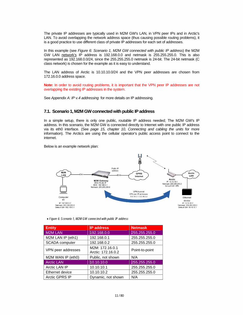
The private IP addresses are typically used in M2M GW's LAN, in VPN peer IPs and in Arctic's LAN. To avoid overlapping the network address space (thus causing possible routing problems), it is a good practice to use different class of private IP addresses for each set of addresses. In this example (see Figure 6: Scenario 1, M2M GW connected with public IP address) the M2M GW LAN network’s IP address is 192.168.0.0 and netmask is 255.255.255.0. This is also represented as 192.168.0.0/24, since the 255.255.255.0 netmask is 24-bit. The 24-bit netmask (C class network) is chosen for the example as it is easy to understand. The LAN address of Arctic is 10.10.10.0/24 and the VPN peer addresses are chosen from 172.16.0.0 address space. Note: In order to avoid routing problems, it is important that the VPN peer IP addresses are not overlapping the existing IP addresses in the system. See Appendix A: IP v.4 addressing for more details on IP addressing. 7.1. Scenario 1, M2M GW connected with public IP address
In a simple setup, there is only one public, routable IP address needed; The M2M GW's IP address. In this scenario, the M2M GW is connected directly to Internet with one public IP address via its eth0 interface. (See page 15, chapter 10, Connecting and cabling the units for more information). The Arctics are using the cellular operator’s public access point to connect to the internet. Below is an example network plan:
• Figure 6: Scenario 1, M2M GW connected with public IP address
Entity IP address Netmask M2M LAN 192.168.0.0 255.255.255.0 M2M LAN IP (eth1) 192.168.0.1 255.255.255.0 SCADA computer 192.168.0.2 255.255.255.0
VPN peer addresses M2M: 172.16.0.1 Arctic: 172.16.0.2 Point-to-point
M2M WAN IP (eth0) Public, not shown N/A Arctic LAN 10.10.10.0 255.255.255.0 Arctic LAN IP 10.10.10.1 255.255.255.0 Ethernet device 10.10.10.2 255.255.255.0 Arctic GPRS IP Dynamic, not shown N/A
12 / 80
• Table 2: Scenario 1, example IP addresses
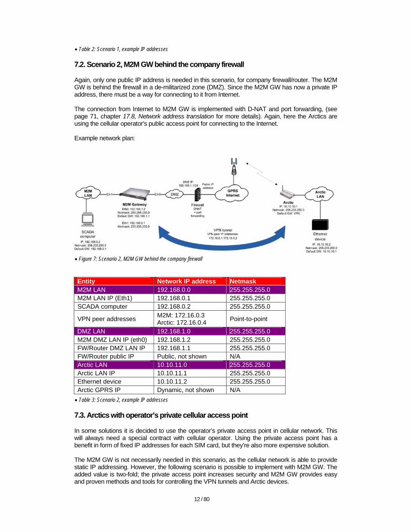
7.2. Scenario 2, M2M GW behind the company firewall
Again, only one public IP address is needed in this scenario, for company firewall/router. The M2M GW is behind the firewall in a de-militarized zone (DMZ). Since the M2M GW has now a private IP address, there must be a way for connecting to it from Internet. The connection from Internet to M2M GW is implemented with D-NAT and port forwarding, (see page 71, chapter 17.8, Network address translation for more details). Again, here the Arctics are using the cellular operator’s public access point for connecting to the Internet. Example network plan:
• Figure 7: Scenario 2, M2M GW behind the company firewall
Entity Network IP address Netmask M2M LAN 192.168.0.0 255.255.255.0 M2M LAN IP (Eth1) 192.168.0.1 255.255.255.0 SCADA computer 192.168.0.2 255.255.255.0
VPN peer addresses M2M: 172.16.0.3 Arctic: 172.16.0.4 Point-to-point
DMZ LAN 192.168.1.0 255.255.255.0 M2M DMZ LAN IP (eth0) 192.168.1.2 255.255.255.0 FW/Router DMZ LAN IP 192.168.1.1 255.255.255.0 FW/Router public IP Public, not shown N/A Arctic LAN 10.10.11.0 255.255.255.0 Arctic LAN IP 10.10.11.1 255.255.255.0 Ethernet device 10.10.11.2 255.255.255.0 Arctic GPRS IP Dynamic, not shown N/A • Table 3: Scenario 2, example IP addresses
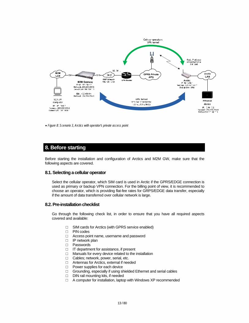
7.3. Arctics with operator’s private cellular access point
In some solutions it is decided to use the operator’s private access point in cellular network. This will always need a special contract with cellular operator. Using the private access point has a benefit in form of fixed IP addresses for each SIM card, but they’re also more expensive solution. The M2M GW is not necessarily needed in this scenario, as the cellular network is able to provide static IP addressing. However, the following scenario is possible to implement with M2M GW. The added value is two-fold; the private access point increases security and M2M GW provides easy and proven methods and tools for controlling the VPN tunnels and Arctic devices.
13 / 80
• Figure 8: Scenario 3, Arctics with operator's private access point
8. Before starting
Before starting the installation and configuration of Arctics and M2M GW, make sure that the following aspects are covered. 8.1. Selecting a cellular operator
Select the cellular operator, which SIM card is used in Arctic if the GPRS/EDGE connection is used as primary or backup VPN connection. For the billing point of view, it is recommended to choose an operator, which is providing flat-fee rates for GRPS/EDGE data transfer, especially if the amount of data transferred over cellular network is large.
8.2. Pre-installation checklist
Go through the following check list, in order to ensure that you have all required aspects covered and available:
□ SIM cards for Arctics (with GPRS service enabled) □ PIN codes □ Access point name, username and password □ IP network plan □ Passwords □ IT department for assistance, if present □ Manuals for every device related to the installation □ Cables; network, power, serial, etc. □ Antennas for Arctics, external if needed □ Power supplies for each device □ Grounding, especially if using shielded Ethernet and serial cables □ DIN rail mounting kits, if needed □ A computer for installation, laptop with Windows XP recommended
14 / 80
9. Tools needed for initial setup
9.1. Place for making the initial setup
It is assumed that the M2M GW and Arctic are locally accessible, while performing the initial configuration. Installing and configuring a distributed environment may cause unnecessary site visits. It is a good practice to configure the Arctic’s locally and first test the connection with the end application. If a serial device is connected, test the serial to TCP/UDP connectivity by connecting the Arctic to local area network. When the serial connection tested, implement the VPN connection and test end-to-end connectivity. After the connectivity has been tested, the Arctics can be placed to the field. 9.2. Installation computer
A computer is needed for configuring the M2M GW and Arctic. The computer - a desktop or a laptop should have at least the following characteristics:
• Ethernet interface, twisted pair (10/100 or optionally Gigabit Ethernet) • Serial port (optional, native serial port preferred over USB-Serial adapter) • Capability of running required software or their OS-dependent equivalents (see chapter
9.4: Software below). 9.3. Cables
• At least "category 5" unshielded twisted pair Ethernet cables are recommended. • A cross-connected Ethernet cable (or an Ethernet switch with direct cables) is needed for
connecting the M2M GW and Arctic to the computer used for configuration. • Optionally, a cross-connected serial cable is needed for connecting via serial interface to
Arctic's console. 9.4. Software
The Windows XP is assumed as the default operating system in this document, but almost any contemporary operating system can be used. Refer to the documentation of any other operating system for achieving the same functionality as Windows XP equipped with the following programs (programs marked as optional are not needed but they may help in certain cases):
• Web browser (Internet Explorer or Firefox, http://www.mozilla.com/en-US/firefox)
• Telnet/SSH client (e.g. PuTTY, http://www.chiark.greenend.org.uk/~sgtatham/putty/download.html) or Windows XP’s native Telnet client.
• SCP program (optional, e.g. WinSCP, http://winscp.net/eng/download.php)
• Wireshark (optional, http://www.wireshark.org/download.html)

15 / 80
10. Connecting and cabling the units
10.1. Unpacking
Save the packages and boxes of the received equipment for possible later use. Follow the local regulations, while disposing of any wrapping materials. 10.2. Environmental specifications
While the temperature and humidity are specified in details (see below) there are other aspects that should be also taken into consideration. The M2M GW should be positioned to reasonably dust free environment. In addition, as with any device equipped with hard disk drive, the M2M GW should not be subjected to excessive shocks or vibration. 10.2.1. M2M GW
Operating temperature 0 to 45 Celsius (30 to 113 Fahrenheit) Storage temperature: -20 to 45 Celsius (-4 to 113 Fahrenheit) Humidity 10 to 90 % RH non-cond.
• Table 4: M2M GW's environmental specifications
See other technical specifications for M2M GW from Viola M2M Gateway User Manual, chapter 12, page 31. For Warranty and safety Instructions, refer to page 5 from the same manual. 10.2.2. Arctic
Operating temperature: 20 to 55 Celsius (4 to 131 Fahrenheit) Storage temperature: 30 to 85 Celsius (22 to 185 Fahrenheit) Humidity: 5 to 85 % RH non cond.
• Table 5: Arctic's environmental specifications
See other technical specifications for the Arctic from the Arctic user’s manual, chapter "Technical Specifications". For Warranty and safety Instructions, refer to chapter "Warranty and Safety Instructions" in the same manual.
11. Cabling
Connect the Ethernet cables and possible serial cables before connecting power supply cables. Verify that the power switch in Arctic is in "Off" position before connecting the power supply cable. 11.1. Cabling the M2M GW
There are two Ethernet connectors at the back side of M2M GW. The first one, marked with number "1" stamped to the right side of the connector, is the WAN port of M2M GW. It is the eth0 interface in M2M's graphical user interface. The second Ethernet connector, marked with number "2" is the LAN port of the M2M GW. It is the eth1 interface in M2M GW's GUI. There are also connectors for local console with analog VGA connector for monitor and either PS/2 or USB ports for local keyboard. The local console is helpful in some situations (e.g. if one has
16 / 80
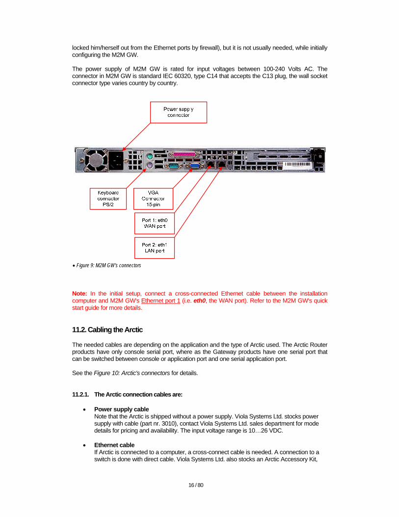
locked him/herself out from the Ethernet ports by firewall), but it is not usually needed, while initially configuring the M2M GW. The power supply of M2M GW is rated for input voltages between 100-240 Volts AC. The connector in M2M GW is standard IEC 60320, type C14 that accepts the C13 plug, the wall socket connector type varies country by country.
• Figure 9: M2M GW's connectors
Note: In the initial setup, connect a cross-connected Ethernet cable between the installation computer and M2M GW's Ethernet port 1 (i.e. eth0, the WAN port). Refer to the M2M GW's quick start guide for more details. 11.2. Cabling the Arctic
The needed cables are depending on the application and the type of Arctic used. The Arctic Router products have only console serial port, where as the Gateway products have one serial port that can be switched between console or application port and one serial application port. See the Figure 10: Arctic's connectors for details. 11.2.1. The Arctic connection cables are:
• Power supply cable Note that the Arctic is shipped without a power supply. Viola Systems Ltd. stocks power supply with cable (part nr. 3010), contact Viola Systems Ltd. sales department for mode details for pricing and availability. The input voltage range is 10…26 VDC.
• Ethernet cable If Arctic is connected to a computer, a cross-connect cable is needed. A connection to a switch is done with direct cable. Viola Systems Ltd. also stocks an Arctic Accessory Kit,
17 / 80
part nr. 3220 (power supply, null modem cable, cross connected Ethernet cable).
• Serial cable for console port When connecting a computer to Arctic’s console port, a cross-connected (null modem cable) is used.
• Serial cable for RS1 application port (Gateways) The RS1 application port is always RS-232 and switchable between console and application (plain data) port. Power off Arctic before changing the switch state.
• Serial cable for RS2 application port (Gateways) The RS2 port is configurable between RS-232 and RS-422/485. Full and half duplex are supported. Power off Arctic before changing the DIP switches’ states.
• Antenna cable (optional) If the Arctic is located inside a cabinet, the signal level of cellular network may not be sufficient for operation when using the standard antenna. An external antenna with a cable equipped with FME connector may be used. The recommendation is to use an omnidirectional antenna, which has even gain in every direction. Antennas having 3 to 9 dBi gain (or even more) are recommended, higher gain is usually better.
11.2.2. Arctic’s Ethernet specifications:
• 10 Base-T or 100 Base-T • Supports auto negotiation • Supports half duplex and full duplex • Shielded Ethernet connection, shield connected to power supply ground
Note: When using shielded cable, consider the possible voltage potential differences. Commonly, the unshielded twisted pair (UTP) cable is the best solution.
11.2.3. Grounding
In order to avoid device failures due to ground loops or due to other grounding problems, it is essential to verify that proper actions are taken regarding the grounding of the equipment. The grounding of the equipment depends on the use case and also on the national electrical and safety regulations. Some best practices for grounding of the equipment are as below:
• Consider whether the Shielded Twisted pair Ethernet cable (STP) is needed at all, if not, use unshielded cable (UTP) to avoid ground loops.
• Use one common grounding point. • For grounding the serial devices, see page 64, chapter 15.7: Grounding.

18 / 80
• Figure 10: Arctic's connectors
12. Configuring the installation environment
This chapter describes the actions needed before the M2M GW and Arctic can be set up. The main task is to prepare the computer that is used in configuring the M2M GW and Arctic. 12.1. Configuring the installation computer
The computer that is used for installing and configuring the Viola Systems M2M solution is called the field engineer's laptop even though a desktop computer can be used as well. Although the instructions below are for Windows XP, almost all modern operating systems can be used.
1. Click "start" button: Figure 11: Windows XP start button
2. Click "Settings" "Control Panel". The Control Panel in Windows XP looks like one of the following:

19 / 80
• Figure 12: XP Control Panel, Category view
• Figure 13: XP Control Panel, Classic view
3. Click "Network connections" icon, which looks like one of the following:
• Figure 14: XP Network connections, classic view
• Figure 15: XP Network connections, category view
4. The Network Connections window opens and the correct network interface will be right-clicked with a mouse:
Choose the LAN interface where the LAN cable is connected to.
• Figure 16: XP LAN connections
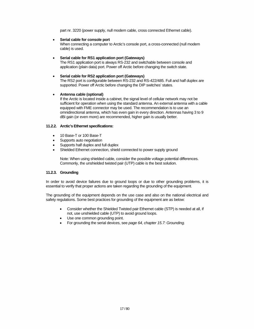
5. Click the correct LAN interface icon with mouse's right button and click "Properties" from the list. You will see the following screen of LAN properties.
20 / 80
• Figure 17: XP LAN properties
6. Scroll down the "This connection uses the following items" list to see the "Internet
Protocol (TCP/IP)". Click the "Internet Protocol (TCP/IP)" in order to make it active and click "Properties".
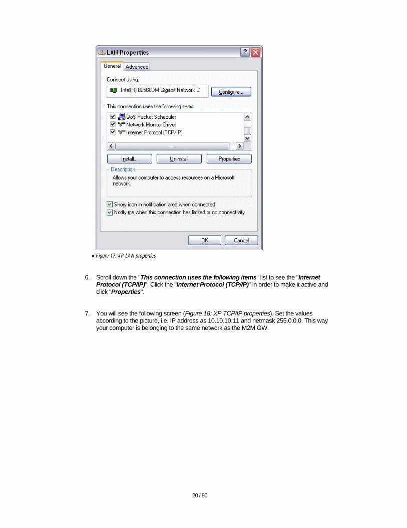
7. You will see the following screen (Figure 18: XP TCP/IP properties). Set the values according to the picture, i.e. IP address as 10.10.10.11 and netmask 255.0.0.0. This way your computer is belonging to the same network as the M2M GW.
21 / 80
• Figure 18: XP TCP/IP properties
8. Click "OK" button to apply the changes.
13. Configuring the M2M Gateway
Once the cables are connected and the installation computer that is used for configuring the M2M GW is set to belong to the same network as M2M GW, the M2M GW can be configured. Follow the next steps for configuring the M2M GW. 13.1. Regarding logging in to the M2M GW
The default URL for accessing the M2M GW is https://10.10.10.10:10000 Note that the M2M GW's Webmin GUI is using the HTTPS (SSL protected HTTP) and the certificate in use is "self signed", which means that it is not among the trusted certificates in web browsers. Therefore, once logged in for the first time, the user must click the “add an exception” to add a security policy exception (Firefox) or click "Continue to this website" (Internet Explorer). 13.2. Logging in using the Firefox web browser
This document describes methods of logging in to the M2M GW's graphical user interface with either Firefox or Internet Explorer. Users of other browsers should consult the documentation of the respective browser regarding the self-signed SSL security certificates. The users of Internet Explorer may wish to skip this section and go to the chapter 13.3 Logging in using the Internet Explorer web browser.
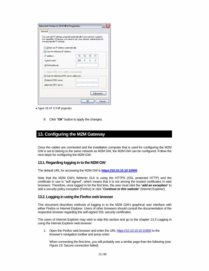
1. Open the Firefox web browser and enter the URL https://10.10.10.10:10000 to the browser’s navigation toolbar and press enter. When connecting the first time, you will probably see a similar page than the following (see Figure 19: Secure connection failed).
22 / 80
• Figure 19: Secure connection failed
The reason for such an error message is that M2M GW's certificate is not in the list of trusted certificates in Firefox. You can safely add an exception for M2M GW's certificate.
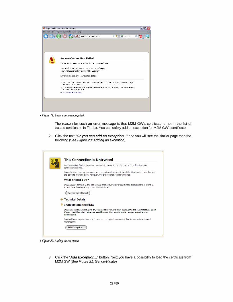
2. Click the text "Or you can add an exception..." and you will see the similar page than the
following (See Figure 20: Adding an exception).
• Figure 20: Adding an exception
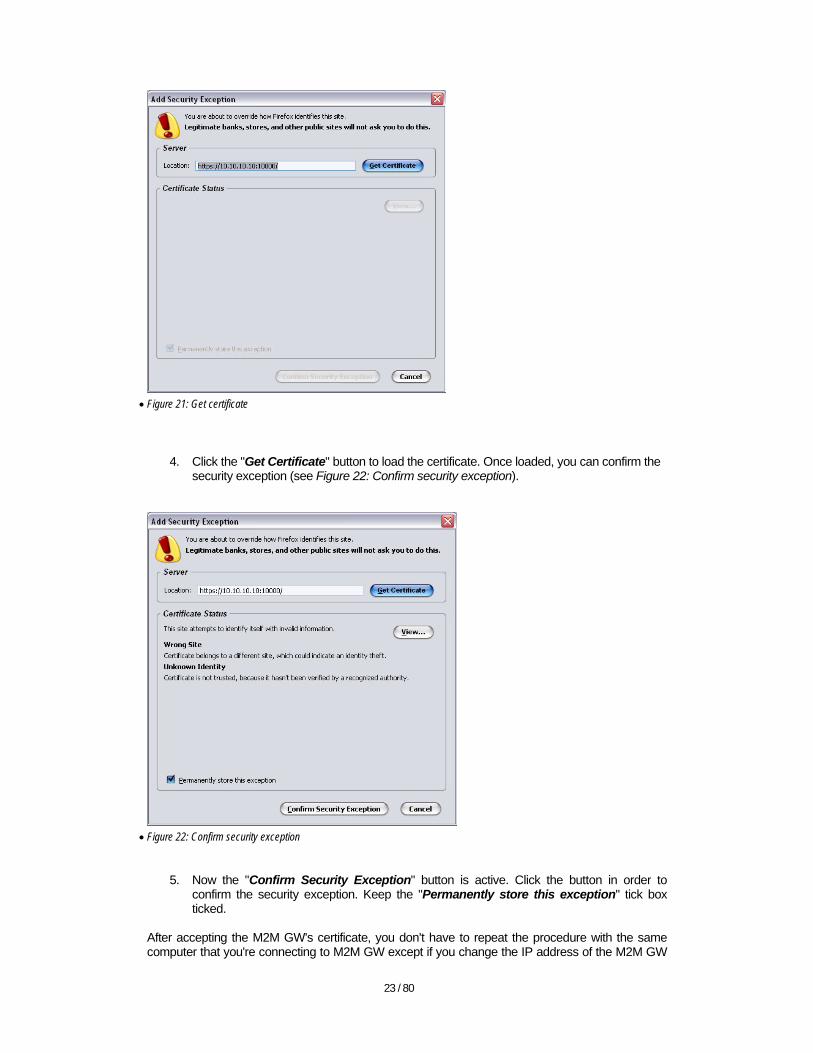
3. Click the "Add Exception..." button. Next you have a possibility to load the certificate from M2M GW (See Figure 21: Get certificate)
23 / 80
• Figure 21: Get certificate
4. Click the "Get Certificate" button to load the certificate. Once loaded, you can confirm the security exception (see Figure 22: Confirm security exception).
• Figure 22: Confirm security exception
5. Now the "Confirm Security Exception" button is active. Click the button in order to
confirm the security exception. Keep the "Permanently store this exception" tick box ticked.
After accepting the M2M GW's certificate, you don't have to repeat the procedure with the same computer that you're connecting to M2M GW except if you change the IP address of the M2M GW

24 / 80
or connect via different network interface (and thus to different IP address of M2M GW). You will need to repeat the same procedure with other computers that you're using for connecting the M2M GW's graphical user interface. After confirming the security exception, the Firefox web browser allows you to connect to the login screen of the M2M GW (See Figure 23: M2M GW's login screen).
• Figure 23: M2M GW's login screen
Log in with the following default user credentials:
• Username: viola-adm • Password: violam2m
You may wish to change the default password later (For more information on changing the password, see page 68, chapter 16.3: Changing passwords). 13.3. Logging in using the Internet Explorer web browser
1. Open the Internet Explorer web browser and enter the URL https://10.10.10.10:10000 to
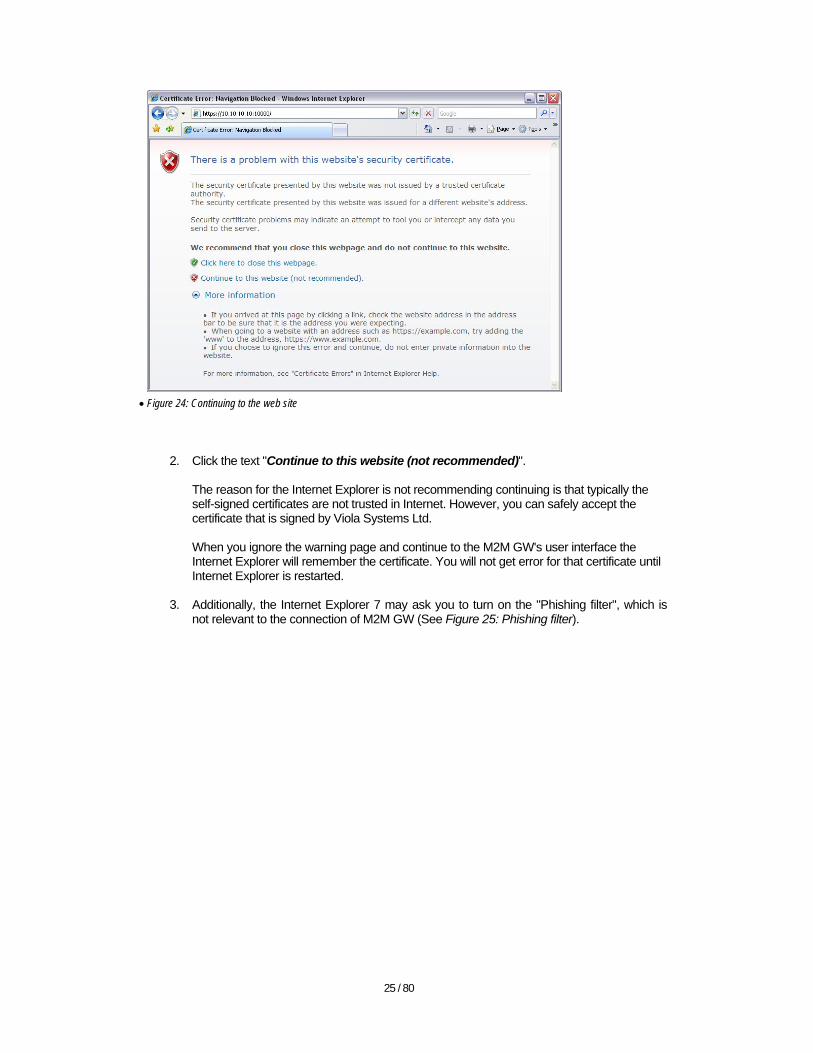
the browser’s navigation toolbar and press enter. When connecting the first time, you will probably see the following screen (Figure 24: Continuing to the web site).
25 / 80
• Figure 24: Continuing to the web site
2. Click the text "Continue to this website (not recommended)". The reason for the Internet Explorer is not recommending continuing is that typically the self-signed certificates are not trusted in Internet. However, you can safely accept the certificate that is signed by Viola Systems Ltd. When you ignore the warning page and continue to the M2M GW's user interface the Internet Explorer will remember the certificate. You will not get error for that certificate until Internet Explorer is restarted.
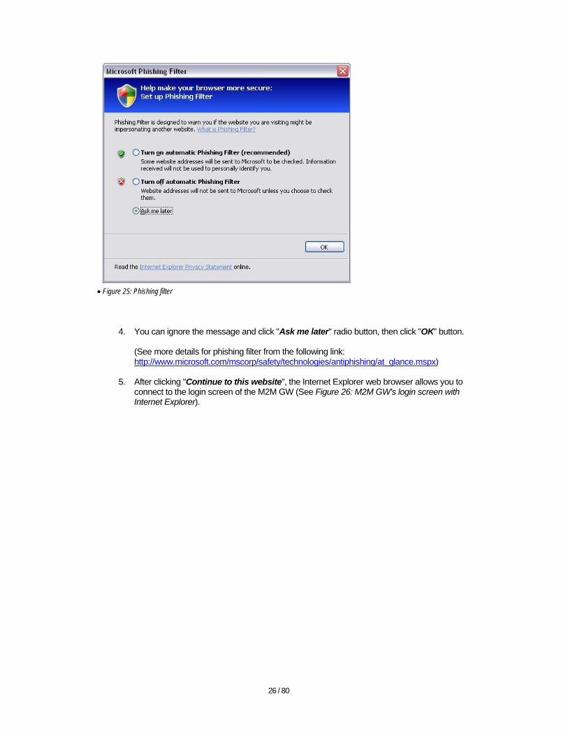
3. Additionally, the Internet Explorer 7 may ask you to turn on the "Phishing filter", which is
not relevant to the connection of M2M GW (See Figure 25: Phishing filter).
26 / 80
• Figure 25: Phishing filter
4. You can ignore the message and click "Ask me later" radio button, then click "OK" button. (See more details for phishing filter from the following link: http://www.microsoft.com/mscorp/safety/technologies/antiphishing/at_glance.mspx)
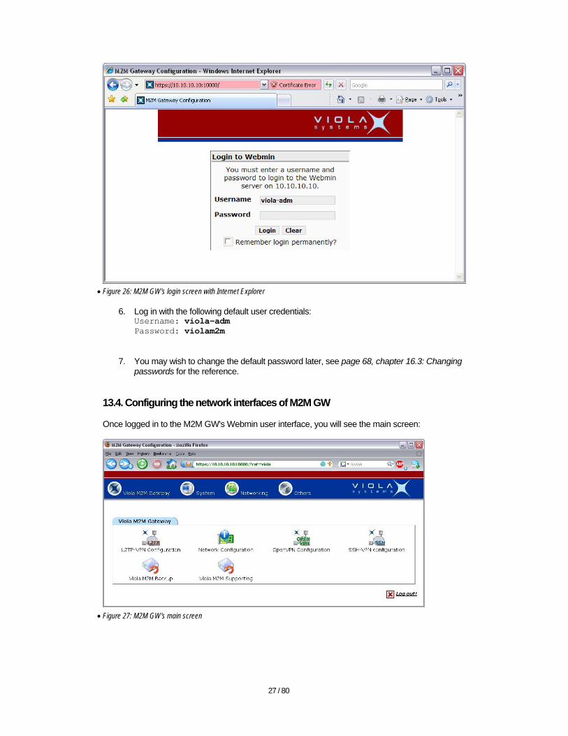
5. After clicking "Continue to this website", the Internet Explorer web browser allows you to
connect to the login screen of the M2M GW (See Figure 26: M2M GW's login screen with Internet Explorer).
27 / 80
• Figure 26: M2M GW's login screen with Internet Explorer
6. Log in with the following default user credentials: Username: viola-adm Password: violam2m
7. You may wish to change the default password later, see page 68, chapter 16.3: Changing passwords for the reference.
13.4. Configuring the network interfaces of M2M GW
Once logged in to the M2M GW's Webmin user interface, you will see the main screen:
• Figure 27: M2M GW's main screen
28 / 80
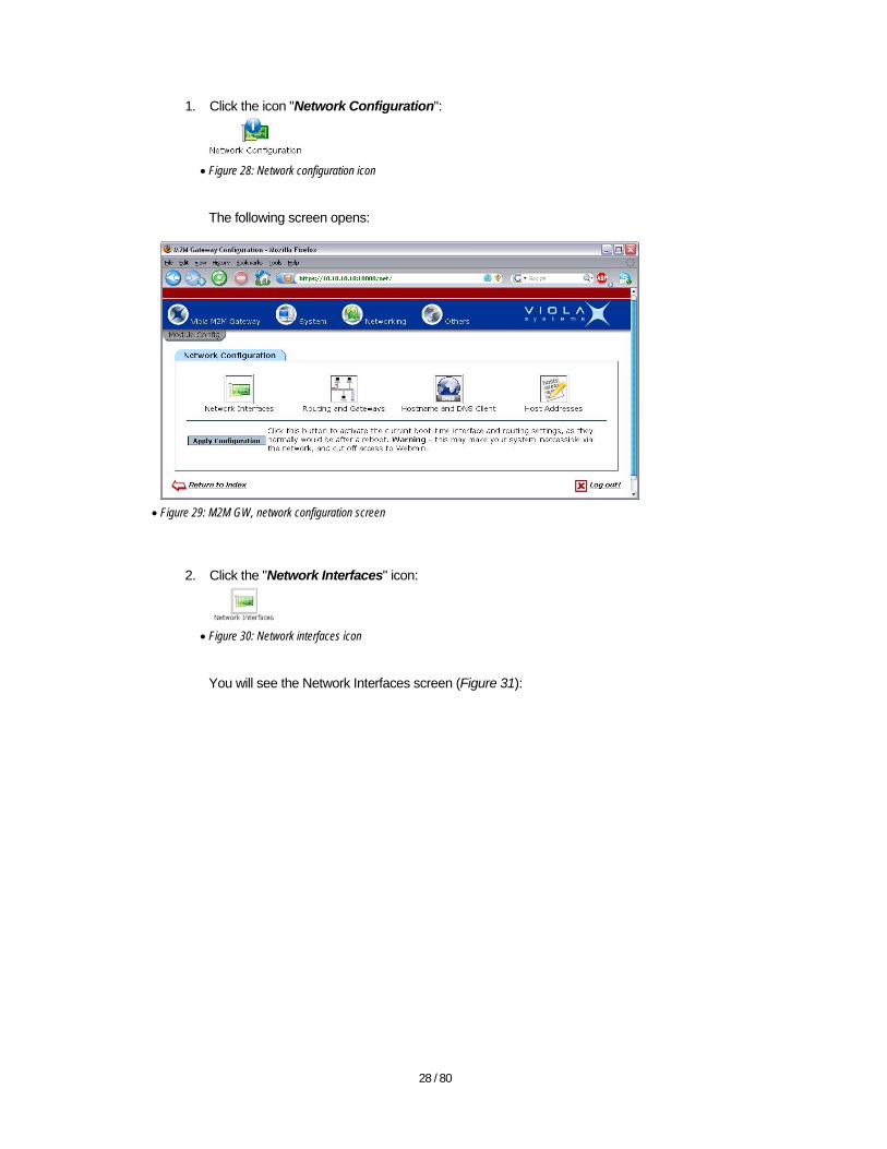
1. Click the icon "Network Configuration":
• Figure 28: Network configuration icon
The following screen opens:
• Figure 29: M2M GW, network configuration screen
2. Click the "Network Interfaces" icon:
• Figure 30: Network interfaces icon
You will see the Network Interfaces screen (Figure 31):
29 / 80
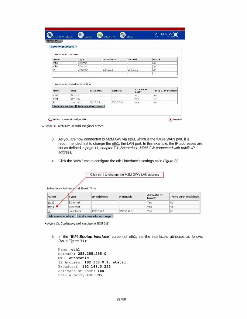
• Figure 31: M2M GW, network interfaces screen
3. As you are now connected to M2M GW via eth0, which is the future WAN port, it is
recommended first to change the eth1, the LAN port. In this example, the IP addresses are set as defined in page 11, chapter 7.1: Scenario 1, M2M GW connected with public IP address.
4. Click the “eth1” text to configure the eth1 interface’s settings as in Figure 32.
• Figure 32: Configuring eth1 interface in M2M GW
5. In the “Edit Bootup Interface” screen of eth1, set the interface’s attributes as follows
(As in Figure 33.):
Name: eth1 Netmask: 255.255.255.0 MTU: Automatic IP Address: 192.168.0.1, static Broadcast: 192.168.0.255 Activate at boot: Yes Enable proxy ARP: No
30 / 80
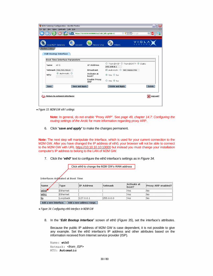
• Figure 33: M2M GW eth1 settings
Note: In general, do not enable “Proxy ARP”. See page 49, chapter 14.7: Configuring the routing settings of the Arctic for more information regarding proxy ARP.
6. Click “save and apply” to make the changes permanent.
Note: The next step will manipulate the interface, which is used for your current connection to the M2M GW. After you have changed the IP address of eth0, your browser will not be able to connect to the M2M GW with URL https://10.10.10.10:10000 but instead you must change your installation computer’s IP address to belong to the LAN of M2M GW.
7. Click the “eth0” text to configure the eth0 interface’s settings as in Figure 34.
• Figure 34: Configuring eth0 interface in M2M GW
8. In the “Edit Bootup Interface” screen of eth0 (Figure 35), set the interface’s attributes.
Because the public IP address of M2M GW is case dependent, it is not possible to give any example. Set the eth0 interface’s IP address and other attributes based on the information received from Internet service provider (ISP).
Name: eth0 Netmask: <from_ISP> MTU: Automatic

31 / 80
IP Address: <from_ISP>, static Broadcast: <from_ISP> Activate at boot: Yes Enable proxy ARP: No
• Figure 35: M2M GW eth0 settings, obtain the correct values from your ISP
Note: In general, do not enable the “Proxy ARP”. See page 49, chapter 14.7: Configuring the routing settings of the Arctic for more information on proxy ARP.
9. Click “save and apply” to make the changes permanent.
Now the browser seems to loose connection, because the eth0 port is now set as WAN port.
10. Change the IP address and netmask of your installation computer to belong to the M2M
GW’s LAN. The example IP address would be 192.168.0.10 and netmask is 255.255.255.0. See the page 18, chapter 12.1: Configuring the installation computer for more information on how to change the installation computer’s IP address, but this time set the IP address and netmask as suggested above.
11. Change the LAN cable from installation computer to M2M GW to Ethernet port 2 (eth1,
LAN port) at M2M GW. After this step, use the following example URL to connect to the M2M GW: https://192.168.0.1:10000. This is the LAN address of M2M GW in the example configuration. If your installation differs from the example, use respective M2M GW’s eth1 IP address to log in to the system.
13.5. Configuring the routing and gateways in M2M GW
1. In the “Network Configuration” screen, click the “Routing and Gateways” icon (Figure 36: Routing and Gateways icon).
32 / 80
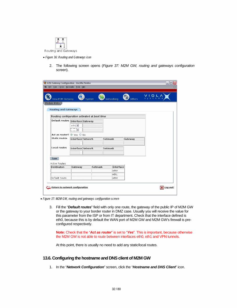
• Figure 36: Routing and Gateways icon
2. The following screen opens (Figure 37: M2M GW, routing and gateways configuration screen).
• Figure 37: M2M GW, routing and gateways configuration screen
3. Fill the “Default routes” field with only one route, the gateway of the public IP of M2M GW or the gateway to your border router in DMZ case. Usually you will receive the value for this parameter from the ISP or from IT department. Check that the interface defined is eth0, because this is by default the WAN port of M2M GW and M2M GW’s firewall is pre-configured respectively. Note: Check that the “Act as router” is set to “Yes”. This is important, because otherwise the M2M GW is not able to route between interfaces eth0, eth1 and VPN tunnels. At this point, there is usually no need to add any static/local routes.
13.6. Configuring the hostname and DNS client of M2M GW
1. In the “Network Configuration” screen, click the “Hostname and DNS Client” icon.
33 / 80
• Figure 38: Hostname and DNS icon
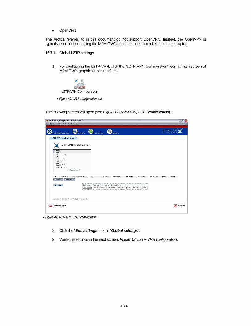
2. The following screen will open:
• Figure 39: M2M GW, hostname and DNS client settings
3. Configure the following options, leave the hostname as m2mgw and search domains as
m2mgw.
• Resolution order When a host address or e.g. web address is given as a name, the M2M GW will search the respective IP address for the name from the /etc/hosts file or from naming services. Most usually the M2M GW is configured so that only the local hosts file is searched.
• DNS servers Typically the M2M GW’s DNS IPs are left blank; this will speed up the SSH-VPN connection establishment. If needed, refer to the parameters received from ISP or from IT department to set the DNS IP addresses.
13.7. Configuring the L2TP-VPN in M2M GW
This chapter describes the L2TP-VPN configuration in M2M GW. Note that the other alternative with Arctic GPRS/EDGE devices is the SSH-VPN. See page 10, chapter 6: Choosing the type of the VPN for more details on which type of VPNs is best for the purpose. See also M2M GW’s user’s manual, Chapter 7: L2TP-VPN Configuration for detailed instructions. The M2M GW supports three types of VPNs:
• L2TP • SSH
34 / 80
• OpenVPN The Arctics referred to in this document do not support OpenVPN. Instead, the OpenVPN is typically used for connecting the M2M GW’s user interface from a field engineer’s laptop. 13.7.1. Global L2TP settings
1. For configuring the L2TP-VPN, click the “L2TP-VPN Configuration” icon at main screen of
M2M GW’s graphical user interface.
• Figure 40: L2TP configuration icon
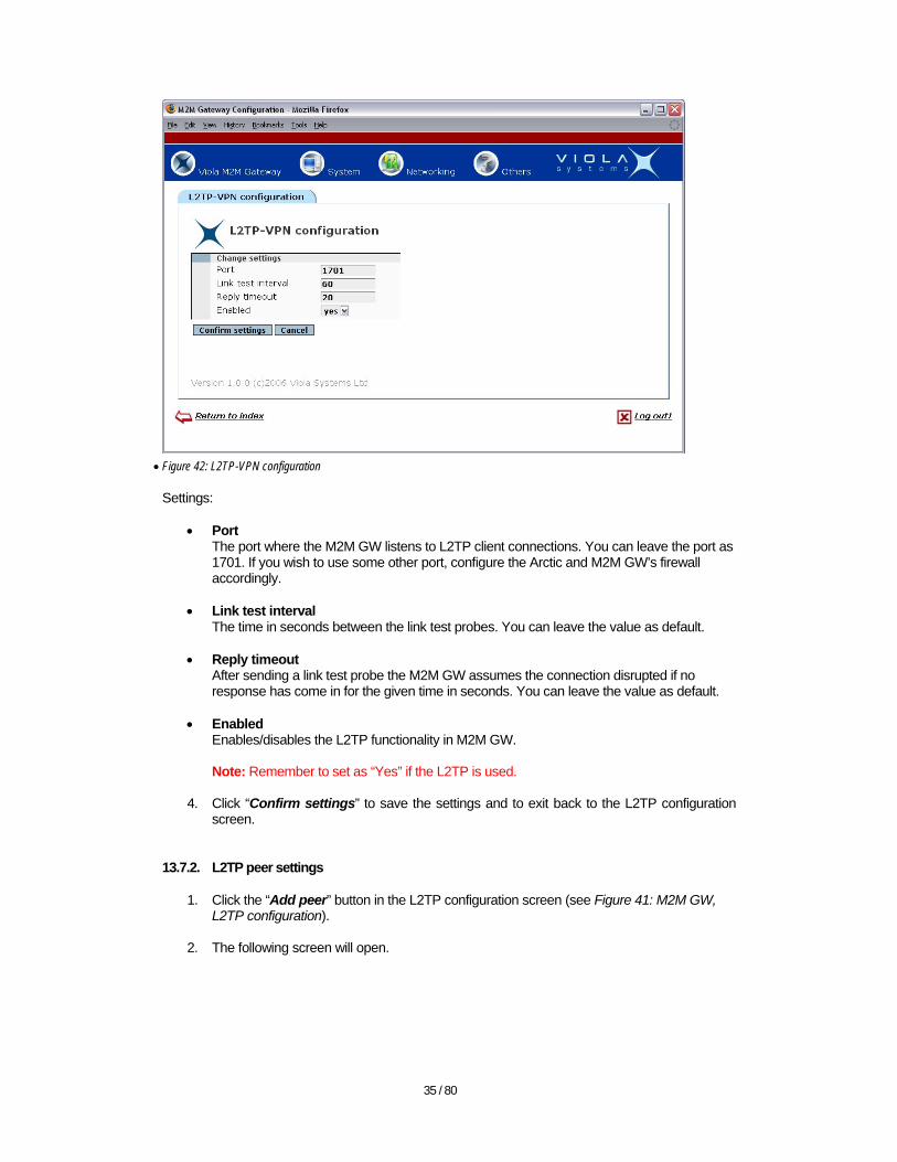
The following screen will open (see Figure 41: M2M GW, L2TP configuration).
• Figure 41: M2M GW, L2TP configuration
2. Click the “Edit settings” text in “Global settings”.
3. Verify the settings in the next screen, Figure 42: L2TP-VPN configuration.
35 / 80
• Figure 42: L2TP-VPN configuration
Settings:
• Port The port where the M2M GW listens to L2TP client connections. You can leave the port as 1701. If you wish to use some other port, configure the Arctic and M2M GW’s firewall accordingly.
• Link test interval
The time in seconds between the link test probes. You can leave the value as default.
• Reply timeout After sending a link test probe the M2M GW assumes the connection disrupted if no response has come in for the given time in seconds. You can leave the value as default.
• Enabled
Enables/disables the L2TP functionality in M2M GW. Note: Remember to set as “Yes” if the L2TP is used.
4. Click “Confirm settings” to save the settings and to exit back to the L2TP configuration
screen. 13.7.2. L2TP peer settings
1. Click the “Add peer” button in the L2TP configuration screen (see Figure 41: M2M GW, L2TP configuration).
2. The following screen will open.
36 / 80
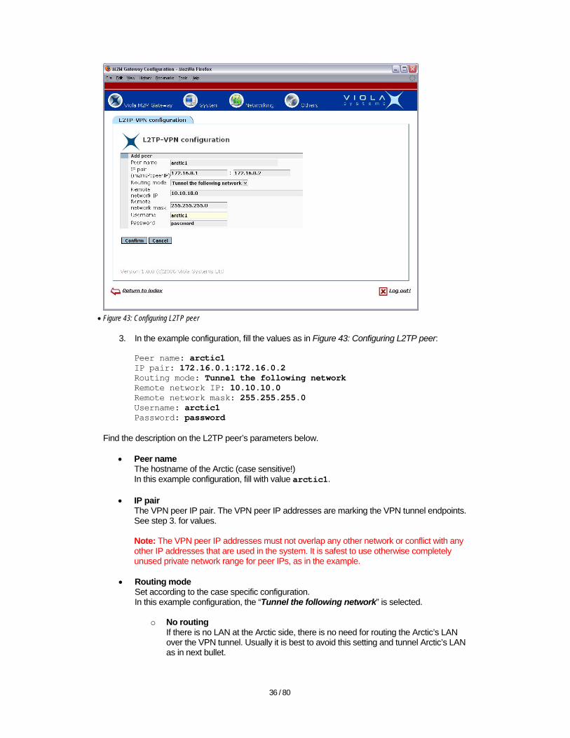
• Figure 43: Configuring L2TP peer
3. In the example configuration, fill the values as in Figure 43: Configuring L2TP peer:
Peer name: arctic1 IP pair: 172.16.0.1:172.16.0.2 Routing mode: Tunnel the following network Remote network IP: 10.10.10.0 Remote network mask: 255.255.255.0 Username: arctic1 Password: password
Find the description on the L2TP peer’s parameters below.
• Peer name The hostname of the Arctic (case sensitive!) In this example configuration, fill with value arctic1.
• IP pair The VPN peer IP pair. The VPN peer IP addresses are marking the VPN tunnel endpoints. See step 3. for values. Note: The VPN peer IP addresses must not overlap any other network or conflict with any other IP addresses that are used in the system. It is safest to use otherwise completely unused private network range for peer IPs, as in the example.
• Routing mode
Set according to the case specific configuration. In this example configuration, the “Tunnel the following network” is selected.
o No routing If there is no LAN at the Arctic side, there is no need for routing the Arctic’s LAN over the VPN tunnel. Usually it is best to avoid this setting and tunnel Arctic’s LAN as in next bullet.
37 / 80
o Tunnel the following network If there are TCP/IP connected devices in Arctic’s LAN (on contrary to the setup, where there are only serial connected devices in Arctic side), the Arctic’s LAN needs to be tunneled over the VPN in order to provide the end-to-end connectivity with M2M GW LAN and Arctic LAN. In this example, there is an Ethernet-connected device, let’s say a computer (with IP address 10.10.10.2), in Arctic’s LAN, which must have a route to M2M GW’s LAN.
• Remote network IP
The LAN on the opposite side of the VPN tunnel, i.e. the Arctic’s LAN network address. Needs to be configured if the “Tunnel the following network” routing mode is chosen. In this example fill with value 10.10.10.0.
• Remote network mask The netmask of the Arctic’s LAN network address. In this example 255.255.255.0.
• Username
The username of the L2TP peer, this must match the Arctic’s username in Arctic’s L2TP-VPN settings. The parameter must also match the hostname of the Arctic. In this example, fill with value arctic1.
• Password
The password of L2TP peer. Must match the password in Arctic’s L2TP-VPN settings. In this example, fill with value password.
4. Click “Confirm” button to apply the changes. 13.7.3. SSH-VPN configuration
The configuration for SSH-VPN is done in similar way than the L2TP-VPN apart from the difference of SSH public keys that has to be exchanged between the M2M GW and Arctic. Without proper SSH public keys in place, the SSH-VPN is not able to work. See the M2M GW’s user’s manual, Chapter 6: SSH-VPN Configuration for details of configuring the SSH-VPN.
1. Click the SSH-VPN icon in M2M GW’s main screen.
• Figure 44: SSH-VPN icon
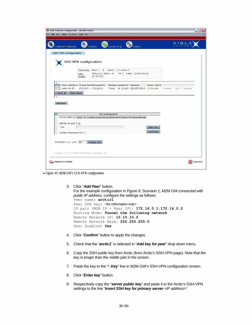
2. The screen in Figure 45: M2M GW's SSH-VPN configuration will open; note that there is already a configured Arctic with the example configuration settings in the figure in this document.
38 / 80
• Figure 45: M2M GW's SSH-VPN configuration
3. Click “Add Peer” button.
For the example configuration in Figure 6: Scenario 1, M2M GW connected with public IP address, configure the settings as follows: Peer name: arctic1 Peer SSH key: <for information only> IP pair (M2M IP : Peer IP): 172.16.0.1:172.16.0.2 Routing Mode: Tunnel the following network Remote Network IP: 10.10.10.0 Remote Network Mask: 255.255.255.0 Peer Enabled: Yes
4. Click “Confirm” button to apply the changes.
5. Check that the “arctic1” is selected in “Add key for peer” drop down menu.
6. Copy the SSH public key from Arctic (from Arctic’s SSH-VPN page). Note that the key is longer than the visible part in the screen.
7. Paste the key to the “- Key” line in M2M GW’s SSH-VPN configuration screen.
8. Click “Enter key” button.
9. Respectively copy the “server public key” and paste it to the Arctic’s SSH-VPN settings to the line “Insert SSH key for primary server <IP address>”
39 / 80
10. Repeat the procedure for all Arctic’s if there is more than one.
11. Click “Lock keys” in order to prevent accidental erasing of the keys.
12. In this example, the “SSH listens on port” field is left as default value 22. Note: If you wish to change the port where the SSH sever is listening the incoming connections, be aware that you must also make respective changes to the M2M GW’s firewall. In addition, the new SSH port will also be used for making SSH connections to the M2M GW in order to access M2M GW’s command line interface. Do not try to test the SSH-VPN peer before the Arctic is configured. The peer checking is done in the similar manner as in L2TP-VPN; see Figure 65: VPN peer test for reference.
14. Configuring the Arctic
While configuring the Arctic via Configurator GUI, it is good to follow certain practices:
• After configuring a setup page, first click “Apply” and then “Commit” buttons. • Give Arctic time to store the settings to non-volatile memory after pressing “Apply”
(approx. 5 seconds) and pressing “Commit” (approx. 10 seconds) button. • Most of the changes become active only after the Arctic is rebooted, so reboot the Arctic
after committing all the changes. The configuration shown in the pictures below is matching the example configuration at page 11, chapter 7.1 Scenario 1, M2M GW connected with public IP address. 14.1. Configuring the Ethernet settings of the Arctic
Find below a description of the menu items in the Arctic’s “Ethernet settings” menu.
40 / 80
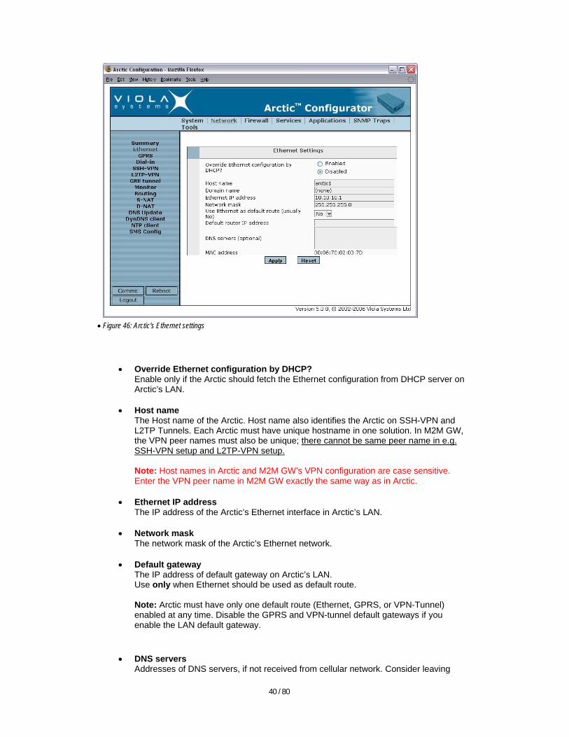
• Figure 46: Arctic's Ethernet settings
• Override Ethernet configuration by DHCP? Enable only if the Arctic should fetch the Ethernet configuration from DHCP server on Arctic’s LAN.
• Host name The Host name of the Arctic. Host name also identifies the Arctic on SSH-VPN and L2TP Tunnels. Each Arctic must have unique hostname in one solution. In M2M GW, the VPN peer names must also be unique; there cannot be same peer name in e.g. SSH-VPN setup and L2TP-VPN setup. Note: Host names in Arctic and M2M GW’s VPN configuration are case sensitive. Enter the VPN peer name in M2M GW exactly the same way as in Arctic.
• Ethernet IP address The IP address of the Arctic’s Ethernet interface in Arctic’s LAN.
• Network mask The network mask of the Arctic’s Ethernet network.
• Default gateway The IP address of default gateway on Arctic’s LAN. Use only when Ethernet should be used as default route. Note: Arctic must have only one default route (Ethernet, GPRS, or VPN-Tunnel) enabled at any time. Disable the GPRS and VPN-tunnel default gateways if you enable the LAN default gateway.
• DNS servers
Addresses of DNS servers, if not received from cellular network. Consider leaving
41 / 80
empty if local hosts do not need DNS services for accessing the Internet through Arctic.
• MAC address
Displays Arctic's MAC/HW address, for informational purposes only.
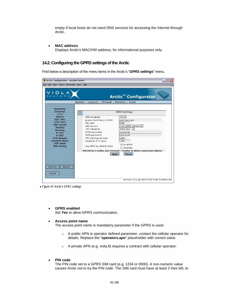
14.2. Configuring the GPRS settings of the Arctic
Find below a description of the menu items in the Arctic’s “GPRS settings” menu.
• Figure 47: Arctic's GPRS settings
• GPRS enabled Set Yes to allow GPRS communication.
• Access point name The access point name is mandatory parameter if the GPRS is used.
o A public APN is operator defined parameter, contact the cellular operator for details. Replace the “operators.apn” placeholder with correct value.
o A private APN (e.g. viola.fi) requires a contract with cellular operator.
• PIN code
The PIN code set to a GPRS SIM card (e.g. 1234 or 0000). A non-numeric value causes Arctic not to try the PIN code. The SIM card must have at least 2 tries left, to

42 / 80
avoid blocking the SIM card if the entered PIN code is not matching the PIN code of the SIM card.
o If a wrong PIN number is entered and Arctic is rebooted, the Arctic will only
try once. After that, the SIM card must be placed to a cellular phone and a correct PIN code must be entered. After a correct PIN code is also entered to the Arctic, the SIM card can be inserted to the Arctic again.
o Note: Do not insert or remove SIM card, while the Arctic has power connected, it may result in corruption of the phone numbers possibly entered to the SIM card.
• DNS servers It is possible either to use the DNS server addresses provided by cellular network or to define the DNS servers manually. Typically it is recommended to use the addresses provided by cellular network if the connection type is GPRS and there are devices in Arctic’s LAN that need name resolution, while going to Internet through Arctic. However, if there is no need for DNS, choose manually configured DNS servers, but leave the fields empty. The SSH-VPN will try to do a reverse DNS lookup for peers, which slows down the SSH-VPN connection establishment.
• Led indication
o When set to “Data only” the GPRS LED blinks, while data is transmitted
o When set to “Informative” the GPRS LED indicates data and GPRS registration status
• GPRS username & password Username and password required by cellular operator’s APN. Verify the values from cellular operator. You may use some ”dummy” values e.g. “username” and “password” even when not required by APN.
• PPP idle timeout If GPRS connection is idle more than defined amount of seconds the Arctic will re-establish the GPRS connection. Note: The ICMP Echo sending interval of “Monitor” should be smaller than PPP idle timeout in order to have uninterrupted connection. See page 48, chapter 15.5. Configuring the Monitor settings of the Arctic for further information for the Monitor functionality.
• Maximum MTU value The maximum size of sent GPRS packet in bytes. Leave as default, unless having problems with large packets.
• Use GPRS as default route
o Set to “Enabled” if GPRS is used as a default route to external networks (typically when plain GPRS is used, without M2M GW or when some hosts in Arctic’s LAN need to access the Internet through Arctic).
o Set to “Disabled” if other connection (VPN tunnel or Ethernet) is used as a default route to external networks. See also page 39, chapter 14.1 Configuring the Ethernet settings of the Arctic.
43 / 80
As opposite to the picture above, you may want to set the “Use GPRS as default route” to “Disabled” in order to follow the example setup.
Note: Arctic should have only one default route (Ethernet, GPRS, or VPN-Tunnel) enabled at any time. Disable the LAN and VPN-tunnel default gateways if you enable the GPRS as default gateway.
14.3. Configuring the Dial-in settings of the Arctic
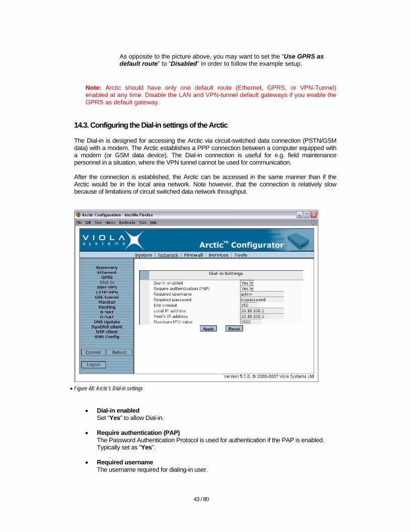
The Dial-in is designed for accessing the Arctic via circuit-switched data connection (PSTN/GSM data) with a modem. The Arctic establishes a PPP connection between a computer equipped with a modem (or GSM data device). The Dial-in connection is useful for e.g. field maintenance personnel in a situation, where the VPN tunnel cannot be used for communication. After the connection is established, the Arctic can be accessed in the same manner than if the Arctic would be in the local area network. Note however, that the connection is relatively slow because of limitations of circuit switched data network throughput.
• Figure 48: Arctic's Dial-in settings
• Dial-in enabled
Set “Yes” to allow Dial-in.
• Require authentication (PAP) The Password Authentication Protocol is used for authentication if the PAP is enabled. Typically set as “Yes”.
• Required username
The username required for dialing-in user.

44 / 80
• Required password The password required for dialing-in user.
• Idle timeout
Timeout in seconds if the connection is idle.
• Local IP address Arctic’s IP address in PPP connection.
• Peer’s IP address
The IP address given to dialing-in user in PPP connection.
• Maximum MTU value The maximum size of PPP packet in bytes.
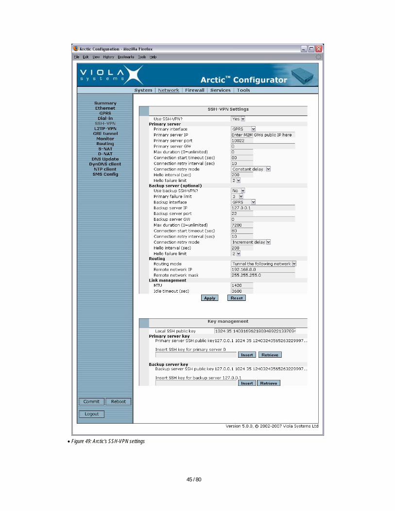
14.4. Configuring the SSH-VPN settings of the Arctic
This step is an alternative to the chapter 14.5: Configuring the L2TP settings of the Arctic. See page 10, chapter 6: Choosing the type of the VPN for information on which VPN to use. Note: Enable only one type of VPN in the same Arctic. If the SSH-VPN is used, it has to be enabled and configured. Find below a description of the menu items in the Arctic’s “SSH-VPN settings” menu.
45 / 80
• Figure 49: Arctic's SSH-VPN settings

46 / 80
• Use SSH-VPN Set to “Yes” to allow SSH-VPN operation
• Interface
Defines the interface (GPRS or Ethernet) to be used when establishing the SSH-VPN tunnel. In this example, the GPRS will be used.
• Primary server IP
The public IP address of the M2M Gateway, where the Arctic connects to. This is the IP address obtained from Internet service provider.
• Primary server port
The TCP port, to which the Arctic will connect when establishing the SSH connection (port where M2M Gateway listens to incoming SSH connections). The default is port 22, but it can be changed from M2M GW’s SSH-VPN configuration. Use the default port 22 in this example.
• Primary server GW
If Ethernet is used, and the M2M Gateway is not in the same LAN as Arctic, this field must contain the IP address of Arctic LAN's default gateway. Leave as 0 in this example.
• Routing mode
o Set as "None" if the SSH-VPN is a default route already and no need for accessing other devices than the M2M GW.
o Set as "Tunnel the following network" for informing the Arctic which network is reachable behind the VPN tunnel at M2M side. This is used e.g. for accessing devices in M2M’s LAN, e.g. SCADA computer.
o Set as “Default route” if the SSH-VPN tunnel is the primary communication channel for all hosts in Arctic’s LAN. Set as "Tunnel the following network" in this example. Note: If “Default route” is enabled, the other default gateways (Ethernet and GPRS) must be disabled.
• SSH-VPN key management
In addition to the VPN parameters, the SSH keys must be exchanged between the Arctic and M2M GW. Enter (copy-paste) the M2M GW’s SSH-VPN server’s key to the line “Insert SSH key for primary server <IP>”. Respectively, enter (copy-paste) the “Local server public key” to the M2M GW’s SSH client configuration. See the Arctic’s and M2M GW’s user’s manuals for more details regarding SSH key exchange. Note: When copying the SSH public keys, be aware that the keys are longer than the visible key part on the screen.
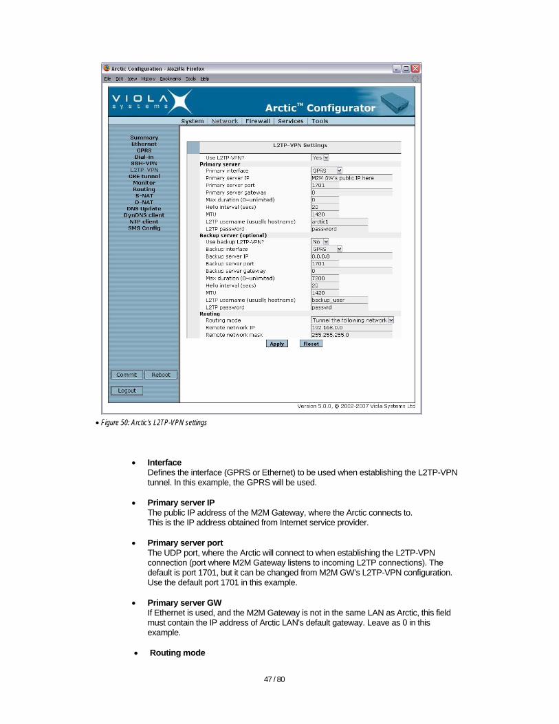
14.5. Configuring the L2TP settings of the Arctic
This step is an alternative to the chapter 14.4: Configuring the SSH-VPN settings of the Arctic. Note: Enable only one type of VPN in the same Arctic. Setting up the L2TP-VPN differs from SSH-VPN, because there is no key exchange between M2M GW and Arctic.
47 / 80
• Figure 50: Arctic's L2TP-VPN settings
• Interface Defines the interface (GPRS or Ethernet) to be used when establishing the L2TP-VPN tunnel. In this example, the GPRS will be used.
• Primary server IP
The public IP address of the M2M Gateway, where the Arctic connects to. This is the IP address obtained from Internet service provider.
• Primary server port The UDP port, where the Arctic will connect to when establishing the L2TP-VPN connection (port where M2M Gateway listens to incoming L2TP connections). The default is port 1701, but it can be changed from M2M GW’s L2TP-VPN configuration. Use the default port 1701 in this example.
• Primary server GW
If Ethernet is used, and the M2M Gateway is not in the same LAN as Arctic, this field must contain the IP address of Arctic LAN's default gateway. Leave as 0 in this example.
• Routing mode
48 / 80
o Set as "None" if there is no need for accessing other devices than the M2M GW.
o Set as "Tunnel the following network" for informing the Arctic which network is reachable behind the VPN tunnel at M2M side. This is used e.g. for accessing devices in M2M’s LAN, e.g. SCADA server.
o Set as “Default route” if the SSH-VPN tunnel is the primary communication channel for all hosts in Arctic’s LAN. Set as "Tunnel the following network" in this example. Note: If “Default route” is enabled, the other default gateways (Ethernet and GPRS) must be disabled.
Leave other settings as defaults. 14.6. Configuring the Monitor settings of the Arctic
The “Monitor” is a failure detection and recovery framework in Arctic. It is implemented with:
• Ping monitor for detecting the failures in communication path • The GPRS/EDGE network connection re-establishment capability • Ability to reboot the device in case of errors
The monitor sends ICMP echo messages (ping) to chosen target at the other end of communication path. The ping target is selected on basis of what is the carrier of the primary connection. Typically the M2M GW’s VPN peer IP address is set as ping target because the VPN tunnel is in most cases the primary communication channel. Note: It is essential to set the Monitor’s ping target. If the ping target is not set, the connectivity is not periodically verified and the Arctic’s connection redundancy and recovery capabilities are not enabled.

49 / 80
• Figure 51: Arctic's Monitor settings
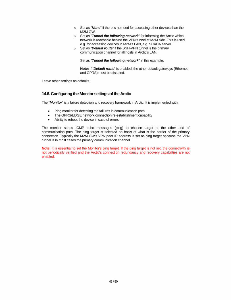
14.7. Configuring the routing settings of the Arctic
Usually there is no need for adding other routes than the network tunneling in VPN settings of the Arctic. If other routes are needed, they can be added with “Routing” menu in Arctic router. Verify the settings:
• The “Act as router” should be enabled. • The “Proxy ARP” should be disabled.
The proxy ARP is used in some special scenarios, where Arctic will answer to ARP queries (with Arctic’s own MAC address) on behalf of the devices that are on the other side of the VPN tunnel. If not carefully planned, enabling the proxy ARP may cause problems. Generally, it is recommended that proxy ARP should be disabled.
50 / 80
• Figure 52: Arctic's routing settings
14.8. Configuring the S-NAT settings of the Arctic
In this example configuration, there is no need for S-NAT since the M2M GW’s and Arctic’s LANs are tunneled over VPN. Note: In a private access point case, it is usually needed to enable S-NAT. The typical use case for S-NAT would be that computers in Arctic LAN need to access Internet via GPRS/EDGE connection. As the computers have private IP addresses (10.10.10.0/24 network), it is not possible for them to access the internet. With S-NAT, the Arctic will change the source IP address of the computer that needs to access the Internet via GPRS to Arctic’s own IP address (masquerade). Respectively, while the packets are coming back to intranet computer, Arctic knows to forward the packets to the correct host in Arctic’s LAN. Refer to page 70, chapter 17.6: Routing for more information on S-NAT/D-NAT.

51 / 80
• Figure 53: Arctic's S-NAT settings
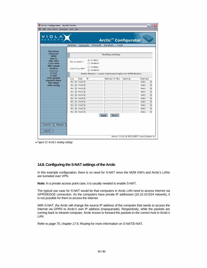
14.9. Configuring the D-NAT settings of the Arctic
In this example configuration, there is no need for D-NAT since the M2M GW’s and Arctic’s LANs are tunneled over VPN. A typical example of D-NAT would be when there are many Arctic’s with overlapping LAN addressing. In such scenario, there may be hosts with the same private class IP address behind different Arctics. It is not possible to arrange routing with same IP address space for several Arctic’s. Instead the VPN peer IPs would be used to differentiate the Arctics and each Arctic would do a D-NAT for packets coming in to Arctics VPN peer IP. The D-NAT would then forward the packets to the host(s) in the Arctic’s LAN based on e.g. the destination port or protocol. Refer to page 70, chapter 17.6: Routing for more information on S-NAT/D-NAT.
52 / 80
• Figure 54: Arctic's D-NAT settings
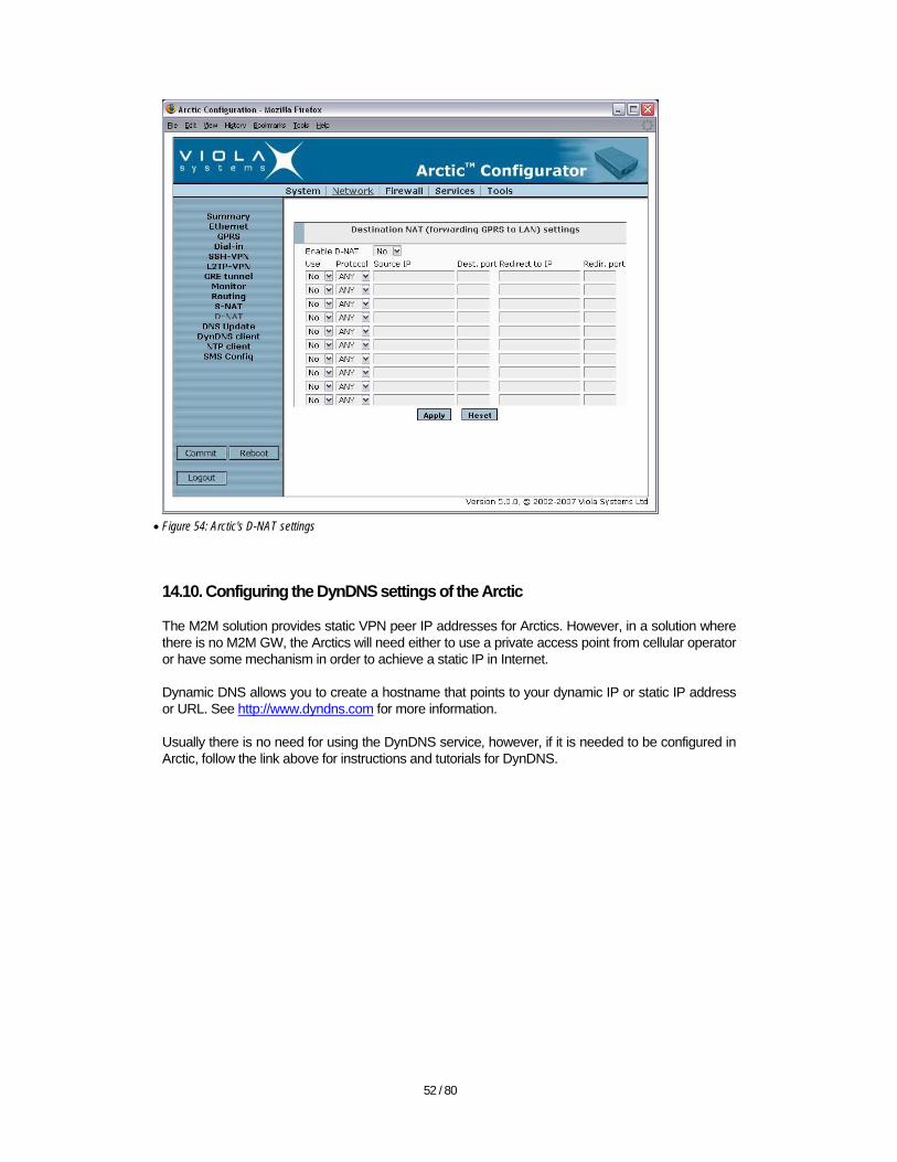
14.10. Configuring the DynDNS settings of the Arctic
The M2M solution provides static VPN peer IP addresses for Arctics. However, in a solution where there is no M2M GW, the Arctics will need either to use a private access point from cellular operator or have some mechanism in order to achieve a static IP in Internet.
Dynamic DNS allows you to create a hostname that points to your dynamic IP or static IP address or URL. See http://www.dyndns.com for more information.
Usually there is no need for using the DynDNS service, however, if it is needed to be configured in Arctic, follow the link above for instructions and tutorials for DynDNS.
53 / 80
• Figure 55: Arctic's DynDNS settings
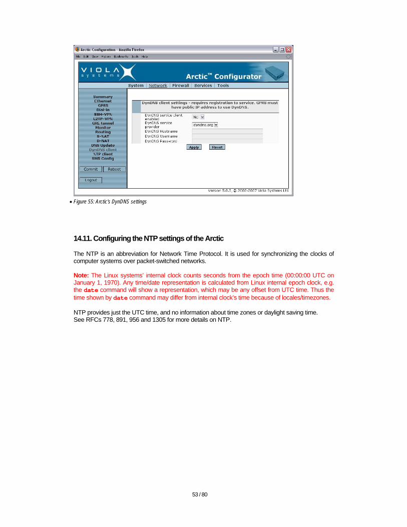
14.11. Configuring the NTP settings of the Arctic
The NTP is an abbreviation for Network Time Protocol. It is used for synchronizing the clocks of computer systems over packet-switched networks. Note: The Linux systems’ internal clock counts seconds from the epoch time (00:00:00 UTC on January 1, 1970). Any time/date representation is calculated from Linux internal epoch clock, e.g. the date command will show a representation, which may be any offset from UTC time. Thus the time shown by date command may differ from internal clock’s time because of locales/timezones. NTP provides just the UTC time, and no information about time zones or daylight saving time. See RFCs 778, 891, 956 and 1305 for more details on NTP.
54 / 80
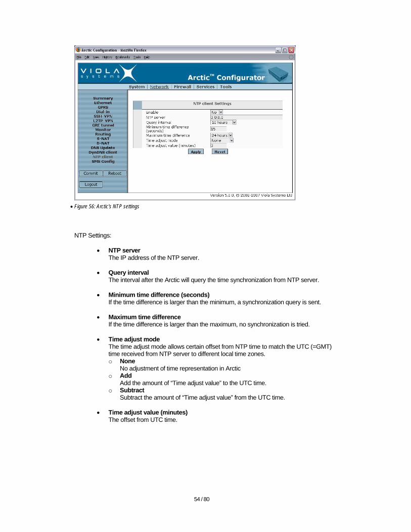
• Figure 56: Arctic's NTP settings
NTP Settings:
• NTP server The IP address of the NTP server.
• Query interval
The interval after the Arctic will query the time synchronization from NTP server.
• Minimum time difference (seconds) If the time difference is larger than the minimum, a synchronization query is sent.
• Maximum time difference
If the time difference is larger than the maximum, no synchronization is tried.
• Time adjust mode The time adjust mode allows certain offset from NTP time to match the UTC (=GMT) time received from NTP server to different local time zones. o None
No adjustment of time representation in Arctic o Add
Add the amount of “Time adjust value” to the UTC time. o Subtract
Subtract the amount of “Time adjust value” from the UTC time.
• Time adjust value (minutes) The offset from UTC time.
55 / 80
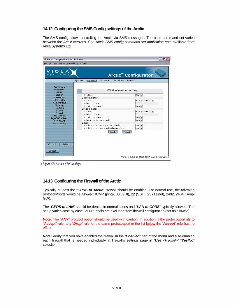
14.12. Configuring the SMS Config settings of the Arctic
The SMS config allows controlling the Arctic via SMS messages. The used command set varies between the Arctic versions. See Arctic SMS config command set application note available from Viola Systems Ltd.
• Figure 57: Arctic's SMS settings
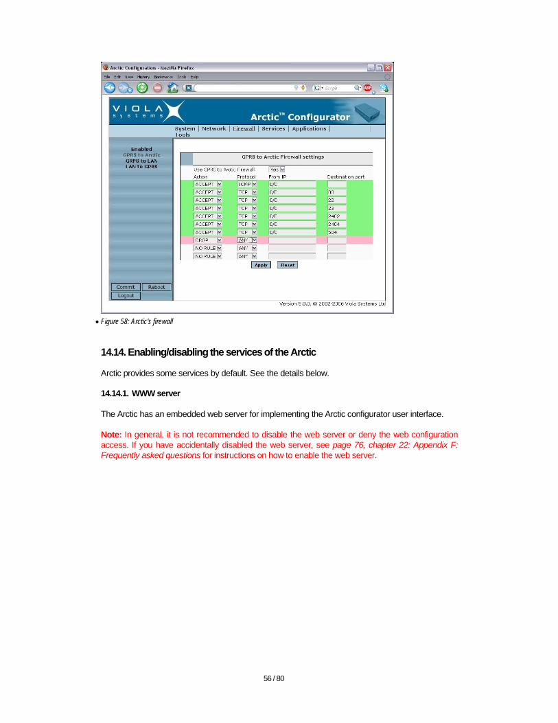
14.13. Configuring the Firewall of the Arctic
Typically at least the “GPRS to Arctic” firewall should be enabled. For normal use, the following protocols/ports would be allowed: ICMP (ping), 80 (GUI), 22 (SSH), 23 (Telnet), 2402, 2404 (Serial GW). The “GPRS to LAN” should be denied in normal cases and “LAN to GPRS” typically allowed. The setup varies case by case. VPN tunnels are excluded from firewall configuration (set as allowed). Note: The “ANY” protocol option should be used with caution. In addition, if the protocol/port fits to “Accept” rule, any “Drop” rule for the same protocol/port in the list below the “Accept” rule has no effect. Note: Verify that you have enabled the firewall in the “Enabled” part of the menu and also enabled each firewall that is needed individually at firewall’s settings page in “Use <firewall>” “Yes/No” selection.
56 / 80
• Figure 58: Arctic's firewall
14.14. Enabling/disabling the services of the Arctic
Arctic provides some services by default. See the details below. 14.14.1. WWW server
The Arctic has an embedded web server for implementing the Arctic configurator user interface.
Note: In general, it is not recommended to disable the web server or deny the web configuration access. If you have accidentally disabled the web server, see page 76, chapter 22: Appendix F: Frequently asked questions for instructions on how to enable the web server.
57 / 80
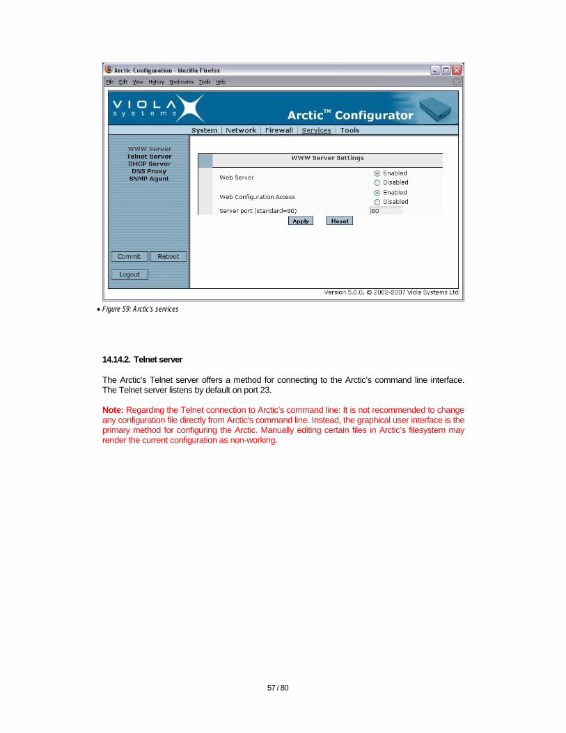
• Figure 59: Arctic's services
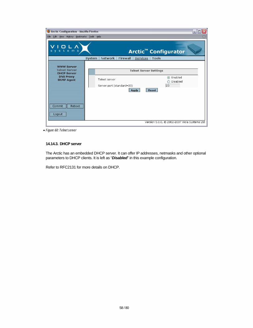
14.14.2. Telnet server
The Arctic’s Telnet server offers a method for connecting to the Arctic’s command line interface. The Telnet server listens by default on port 23. Note: Regarding the Telnet connection to Arctic’s command line: It is not recommended to change any configuration file directly from Arctic’s command line. Instead, the graphical user interface is the primary method for configuring the Arctic. Manually editing certain files in Arctic’s filesystem may render the current configuration as non-working.
58 / 80
• Figure 60: Telnet server
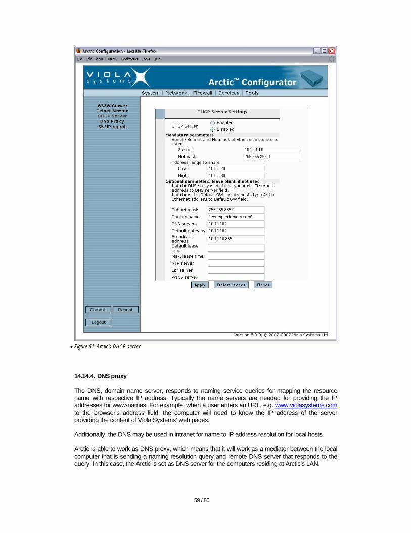
14.14.3. DHCP server
The Arctic has an embedded DHCP server. It can offer IP addresses, netmasks and other optional parameters to DHCP clients. It is left as “Disabled” in this example configuration.
Refer to RFC2131 for more details on DHCP.
59 / 80
• Figure 61: Arctic's DHCP server
14.14.4. DNS proxy
The DNS, domain name server, responds to naming service queries for mapping the resource name with respective IP address. Typically the name servers are needed for providing the IP addresses for www-names. For example, when a user enters an URL, e.g. www.violasystems.com to the browser’s address field, the computer will need to know the IP address of the server providing the content of Viola Systems’ web pages. Additionally, the DNS may be used in intranet for name to IP address resolution for local hosts. Arctic is able to work as DNS proxy, which means that it will work as a mediator between the local computer that is sending a naming resolution query and remote DNS server that responds to the query. In this case, the Arctic is set as DNS server for the computers residing at Arctic’s LAN.
60 / 80
• Figure 62: Arctic's DNS proxy
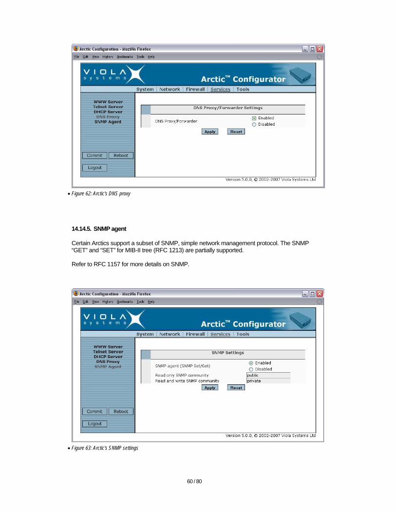
14.14.5. SNMP agent
Certain Arctics support a subset of SNMP, simple network management protocol. The SNMP “GET” and “SET” for MIB-II tree (RFC 1213) are partially supported. Refer to RFC 1157 for more details on SNMP.
• Figure 63: Arctic's SNMP settings
61 / 80
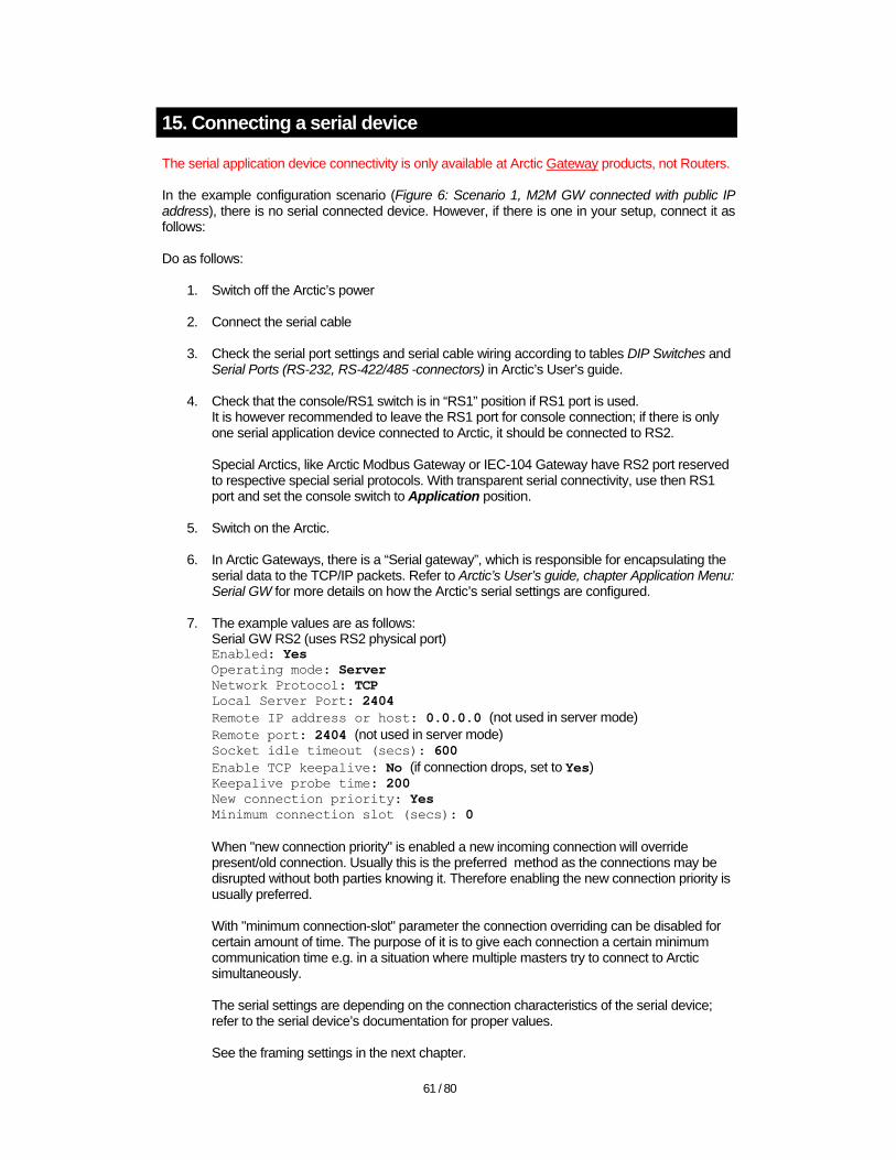
15. Connecting a serial device
The serial application device connectivity is only available at Arctic Gateway products, not Routers. In the example configuration scenario (Figure 6: Scenario 1, M2M GW connected with public IP address), there is no serial connected device. However, if there is one in your setup, connect it as follows: Do as follows:
1. Switch off the Arctic’s power
2. Connect the serial cable
3. Check the serial port settings and serial cable wiring according to tables DIP Switches and Serial Ports (RS-232, RS-422/485 -connectors) in Arctic’s User’s guide.
4. Check that the console/RS1 switch is in “RS1” position if RS1 port is used. It is however recommended to leave the RS1 port for console connection; if there is only one serial application device connected to Arctic, it should be connected to RS2. Special Arctics, like Arctic Modbus Gateway or IEC-104 Gateway have RS2 port reserved to respective special serial protocols. With transparent serial connectivity, use then RS1 port and set the console switch to Application position.
5. Switch on the Arctic.
6. In Arctic Gateways, there is a “Serial gateway”, which is responsible for encapsulating the serial data to the TCP/IP packets. Refer to Arctic’s User’s guide, chapter Application Menu: Serial GW for more details on how the Arctic’s serial settings are configured.
7. The example values are as follows: Serial GW RS2 (uses RS2 physical port) Enabled: Yes Operating mode: Server Network Protocol: TCP Local Server Port: 2404 Remote IP address or host: 0.0.0.0 (not used in server mode) Remote port: 2404 (not used in server mode) Socket idle timeout (secs): 600 Enable TCP keepalive: No (if connection drops, set to Yes) Keepalive probe time: 200 New connection priority: Yes Minimum connection slot (secs): 0 When "new connection priority" is enabled a new incoming connection will override present/old connection. Usually this is the preferred method as the connections may be disrupted without both parties knowing it. Therefore enabling the new connection priority is usually preferred. With "minimum connection-slot" parameter the connection overriding can be disabled for certain amount of time. The purpose of it is to give each connection a certain minimum communication time e.g. in a situation where multiple masters try to connect to Arctic simultaneously. The serial settings are depending on the connection characteristics of the serial device; refer to the serial device’s documentation for proper values. See the framing settings in the next chapter.
62 / 80
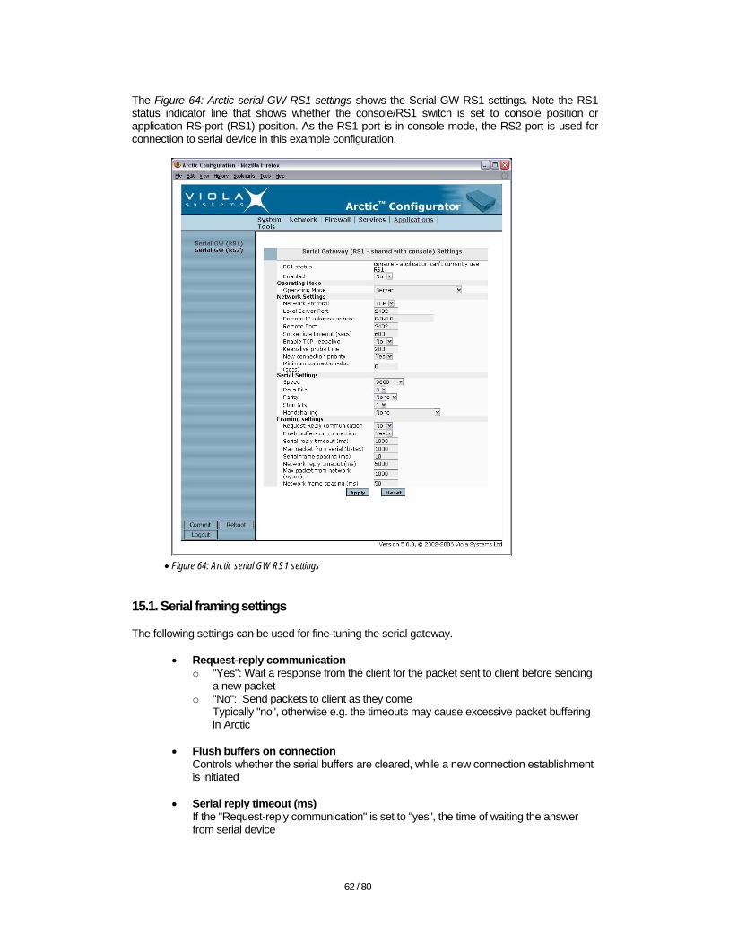
The Figure 64: Arctic serial GW RS1 settings shows the Serial GW RS1 settings. Note the RS1 status indicator line that shows whether the console/RS1 switch is set to console position or application RS-port (RS1) position. As the RS1 port is in console mode, the RS2 port is used for connection to serial device in this example configuration.
• Figure 64: Arctic serial GW RS1 settings
15.1. Serial framing settings
The following settings can be used for fine-tuning the serial gateway.
• Request-reply communication o "Yes": Wait a response from the client for the packet sent to client before sending
a new packet o "No": Send packets to client as they come
Typically "no", otherwise e.g. the timeouts may cause excessive packet buffering in Arctic
• Flush buffers on connection Controls whether the serial buffers are cleared, while a new connection establishment is initiated
• Serial reply timeout (ms) If the "Request-reply communication" is set to "yes", the time of waiting the answer from serial device
63 / 80
• Network reply timeout (ms) If the "Request-reply communication" is set to "yes", the time of waiting the answer from IP device
• Max packet from serial (bytes) The max. amount of bytes received from serial device, after which the packet is sent
• Max packet from network (bytes) The max. amount of bytes received from the IP device, after which the packet is sent
• Serial frame spacing (ms) The time of a pause in serial traffic, after which the already received data is sent
• Network frame spacing (ms) The time of a pause in IP traffic, after which the already received data is sent
15.2. Serial GW modes
The Arctic Gateway products have two modes of operation, while converting the serial traffic for TCP/IP connection.
• Server Arctic will wait TCP/UDP connections coming to its serial GW (TCP/IP) local port. Once the SCADA server establishes the connection, Arctic is able to send the events, as they come from serial line, via TCP/IP to SCADA server without polling. Server mode is typically used.
• Client Arctic will connect to an IP address and TCP/UDP port of a server in order to send the serial events over TCP/IP.
15.3. Serial ports
The Arctic, depending on the model, supports one RS-232 serial port only for console connection or two serial ports, one RS-232 switchable between console and application and one port switchable between RS-232 and RS-422/485. The RS-485 and RS-422 ports are using differential (balanced) signaling providing good noise immunity. 15.4. Cabling
Arctic is a DTE (data terminal equipment) device as computers in general are. Serial devices, like e.g. modems are DCE (data communications equipment) devices. In practice, this means that if you connect the Arctic to a computer, a cross-connected cable is to be used. If the Arctic is connected to a serial device other than computer, check the serial device’s documentation of whether it acts like DCE or DTE equipment. 15.5. RS-485 characteristics
• Also known as RS-485 Half Duplex, RS-485 2-wire • Same pair is used to transmit and receive data • Only one device can transmit on the bus simultaneously because the bus is shared
15.6. RS-422 characteristics
• Also known as RS-485 Full Duplex, RS-485 4-wire • Separate pairs for transmit and reception

64 / 80
• Only one device can command the bus, slaves can’t speak with each other • A device can transmit and receive simultaneously (full duplex)
15.7. Grounding
Although data transmission is balanced in RS-485, a proper grounding may be required if the distance between devices is long and/or they don’t otherwise share the common ground. The most common reason for RS-485/422 circuit damages is the excessive potential difference between the devices. When separate grounding is required connect each remote device to the common ground wire. Connect the common ground to Arctic’s signal ground (pin 5) and to serial connector chassis. 15.8. Termination
Usually short lines and small data rates (less than 115200 bps) do not require termination. The purpose of the termination is to attenuate the reflections on the bus. The value of termination resistor should match the characteristic impedance of the cable. Note: The termination causes plenty of load to the bus and increases the idle state power consumption. It should be used only when required.
16. Testing the solution
The testing procedure below has checkboxes, while following the procedure; you may wish to check the checkboxes, as you go through the list. 16.1. Testing the console login
For M2M GW, there is a possibility to log in via local keyboard (USB or PS/2) and display (15-pin sub-D, analog connector) and for Arctic, there is a possibility to use serial console login (RS-232, 19200-N-8-1, crossed cable). 16.1.1. Testing Arctic’s serial connection
1. Check that the Arctic is powered off.
2. Connect a cross-connected serial cable between Arctic and installation computer.
3. In installation computer use e.g. PuTTY or Windows HyperTerminal (Start All Programs Accessories Communications HyperTerminal). Use the following settings in HyperTerminal: New connection name: Arctic Connect using: <the serial port of the computer, e.g. COM1> Bits per second: 19200 Data bits: 8 Parity: None Stop bits: 1 Flow Control: none
4. Switch on the Arctic and wait couple of seconds.
5. You should see the Arctic’s login prompt.
6. Log in as root user, the password by default is empty
Test 1: Test the Arctic login with steps above in order to verify the connection procedure.
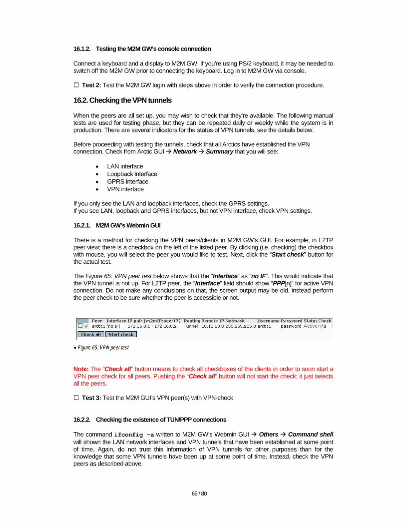
65 / 80
16.1.2. Testing the M2M GW’s console connection
Connect a keyboard and a display to M2M GW. If you’re using PS/2 keyboard, it may be needed to switch off the M2M GW prior to connecting the keyboard. Log in to M2M GW via console.
Test 2: Test the M2M GW login with steps above in order to verify the connection procedure. 16.2. Checking the VPN tunnels
When the peers are all set up, you may wish to check that they’re available. The following manual tests are used for testing phase, but they can be repeated daily or weekly while the system is in production. There are several indicators for the status of VPN tunnels, see the details below. Before proceeding with testing the tunnels, check that all Arctics have established the VPN connection. Check from Arctic GUI Network Summary that you will see:
• LAN interface • Loopback interface • GPRS interface • VPN interface
If you only see the LAN and loopback interfaces, check the GPRS settings. If you see LAN, loopback and GPRS interfaces, but not VPN interface, check VPN settings. 16.2.1. M2M GW’s Webmin GUI
There is a method for checking the VPN peers/clients in M2M GW’s GUI. For example, in L2TP peer view; there is a checkbox on the left of the listed peer. By clicking (i.e. checking) the checkbox with mouse, you will select the peer you would like to test. Next, click the “Start check” button for the actual test. The Figure 65: VPN peer test below shows that the “Interface” as “no IF”. This would indicate that the VPN tunnel is not up. For L2TP peer, the “Interface” field should show “PPP[n]” for active VPN connection. Do not make any conclusions on that, the screen output may be old, instead perform the peer check to be sure whether the peer is accessible or not.
• Figure 65: VPN peer test
Note: The “Check all” button means to check all checkboxes of the clients in order to soon start a VPN peer check for all peers. Pushing the “Check all” button will not start the check; it just selects all the peers.
Test 3: Test the M2M GUI’s VPN peer(s) with VPN-check 16.2.2. Checking the existence of TUN/PPP connections
The command ifconfig –a written to M2M GW’s Webmin GUI Others Command shell will shown the LAN network interfaces and VPN tunnels that have been established at some point of time. Again, do not trust this information of VPN tunnels for other purposes than for the knowledge that some VPN tunnels have been up at some point of time. Instead, check the VPN peers as described above.

66 / 80
It is always best first to check the Network Summary for existence of GPRS and VPN interfaces in Arctics, if the Arctic GUIs are accessible. 16.2.3. Pinging the VPN peer on the other side of the tunnel
A good method of knowing that the VPN tunnel is established and the VPN peer is alive is to ping the other end of the VPN tunnel. Use VPN peer IPs for testing. Note: In Arctic, the ping command with only IP address as an argument will cause the Arctic to endlessly ping the target. This is typically unwanted since the ping command may be accidentally left running thus causing high billing for GPRS connection. Always use –c option (restrict the count of ICMP echo messages sent) as in the following example: In M2M GW: ping –c5 172.16.0.2
Test 4: Test that the M2M GW is able to ping the Arctic’s VPN peer IP In Arctic: ping –c5 172.16.0.1
Test 5: Test that the Arctic is able to ping the M2M GW’s VPN peer IP If the system is not properly configured, there is a danger that the target for pinging is not in the opposite end of VPN tunnel, but there is a local host with the same IP. The local host will answer the ping very fast (within some milliseconds) and this is a good indicator that the setup is not correct. The ping roundtrip time over GPRS should be several hundreds of milliseconds, at least. If respectively configured, you can also ping the hosts in Arctic’s LAN from a host in M2M GW’s LAN (remember to check that a possible firewall in target host is not blocking the ping messages). This will require that the routing is arranged as e.g. in the example configuration, see Figure 6: Scenario 1, M2M GW connected with public IP address (with “Tunnel the following network” settings). 16.2.4. Arctic LAN
If there is a LAN behind the Arctic as in the example configuration the 10.10.10.0/24 LAN, it should be tested that the Arctic is able to connect to devices in the LAN. In the example, there is an Ethernet device with IP 10.10.10.2. Ping the Arctic and Ethernet device from each others. Note that if the Ethernet device is a computer, it may probably have a firewall configured, which blocks the ICMP echo (=ping) messages. Consider shutting down the firewall or making an exception for ICMP messages, while testing.
Test 6: Test the Arctic’s connectivity to devices in Arctic’s LAN (if present). 16.2.5. M2M GW’s WAN
The M2M GW needs an access to the Internet or another TCP/IP connected network for establishing a VPN connection to the Arctic. Test that the M2M GW is able to ping the default gateway of M2M GW’s eth0 (WAN) interface.
Test 7: Test the M2M GW’s connection to eth0 default gateway. 16.2.6. M2M GW’s LAN
The M2M GW may also be connected to the LAN. Typically this is the LAN where the SCADA or other controlling/monitoring server is residing. Test the connection from SCADA server to M2M GW by pinging the M2M GW’s eth1 LAN address (192.168.0.1 in this example configuration) from SCADA server (192.168.0.2 in this example).

67 / 80
Test 8: Test the SCADA server’s connection to eth1 interface of M2M GW.
16.2.7. End-to-end connectivity
Last, test the SCADA server’s ability to connect to the Ethernet (or serial) device in Arctic’s LAN. There are two options, a) Ethernet end device or b) Serial end device. Test the one that matches your setup. Ethernet device
• Ping the Ethernet device (10.10.10.2) from SCADA server. • Test the SCADA control software’s ability to connect to the device (RTU, remote
terminal unit) that is controlled. In this example the RTU is referred as the “Ethernet device”.
Test 9 a: Test the SCADA server’s connection to end device, connected to Arctic via Ethernet.
Serial device If the RTU is serial connected, you will need to use the Arctic’s VPN peer address (172.16.0.2 in this example) and the port where the Arctic’s serial GW listens to the connections coming from SCADA server. Configure the Arctic’s serial GW to match the TCP/UDP port that is used by SCADA rather than changing the SCADA port that is used for connecting the RTU. Refer to the SCADA documentation for finding a proper TCP/UDP port.
Test 9b: Test the SCADA server’s connection to end device, connected to Arctic via serial line. The tests above will help you to verify the communication path segment by segment. If some segment fails the test, it is easier to focus the troubleshooting efforts to the particular segment. 16.2.8. Log files
This step is not belonging to the actual testing phase but will rather give additional information on how the VPN connections are seen in log files. In M2M GW, the information related to VPN tunnels can be seen in the following log files, you can list them in M2M GW’s GUI Others Command shell.
• SSH-VPN tunnels Log file: /var/log/secure command: tail -100 /var/log/secure
• L2TP tunnels Log file: /var/log/tunnel command: tail -100 /var/log/tunnel
The “-100” in “tail” command will define that last 100 lines of the file is shown. To see the whole file, use the command “cat”, e.g. cat /var/log/tunnel. The log files will indicate the login attempts of the Arctics, therefore, the log markings are a good indication whether the Arctics are able to at least try the login and VPN tunnel establishment. Examples: The incoming SSH-VPN connection attempt from Arctic will show in /var/log/secure as follows: Mar 26 09:12:24 m2mgw sshd[<PID>]: Connection from <GPRS IP address> port <port> The established SSH-VPN connection will show in /var/log/secure as follows: Mar 24 03:34:17 m2mgw sshd[<PID>]: Accepted rsa for vvpn from <GPRS IP address> port <port>

68 / 80
Mar 24 03:34:19 m2mgw sudo: vvpn : TTY=unknown ; PWD=/home/vvpn ; USER=root ; COMMAND=/usr/sbin/pppd noauth nodetach notty call <SSH-VPN peer name> 16.3. Changing passwords
After the installation and testing, it is recommended to change the default passwords. The passwords can be changed from graphical user interfaces of M2M GW and Arctic. Follow the instructions below.
16.3.1. Changing the passwords in M2M GW
In M2M GW’s Webmin GUI, navigate to “System” “Change Passwords”. Select a user, which password is changed. Enter the new password twice to the respective fields in GUI. Keep the “Change password in other modules” tick box ticked. Click “Change” to apply the changes. 16.3.2. Changing the root password in Arctic
In Arctic Configurator GUI, navigate to “System” “Password” and enter the new root password two times to the respective fields in GUI. Click “Apply” to make the change.
17. Appendix A: IP v.4 addressing and networking
The following introduction describes the terms related to the planning and setting up an end to end network connection with Viola Systems equipment. See the RFC 791 document, available at http://www.ietf.org/ for detailed information on IP v.4. 17.1. OSI- and TCP -models
The OSI-model is usually referenced, while describing the intercommunication between computers and computer networks. Even as the TCP/IP protocol model doesn't directly map into the OSI-model, it is useful to understand the different layers in data transfer. Unit Layer Function example Data 7 Application Networking process to application Data 6 Presentation Data encryption Data 5 Session Host to host connections Segment 4 Transport End-to-end connections Packet 3 Network Logical addressing Frame 2 Data link Physical addressing Bit 1 Physical Wire
• Table 6: OSI-model
There are plenty of tutorials in Internet regarding OSI- and TCP/IP models. Refer to e.g. Wikipedia for more information. 17.2. Public and private IP addresses
The public IP addresses are routable unique addresses in Internet. Private IP addresses are not routable in Internet, but they can be routed between the private networks. The Viola Systems M2M solution needs at least one public IP address, for the connection to the Internet. It may be assigned to M2M Gateway (see Figure 6: Scenario 1, M2M GW connected with public IP address) or it can be a company router, which has to be configured to forward packets to M2M (see Figure 7: Scenario 2, M2M GW behind the company firewall).
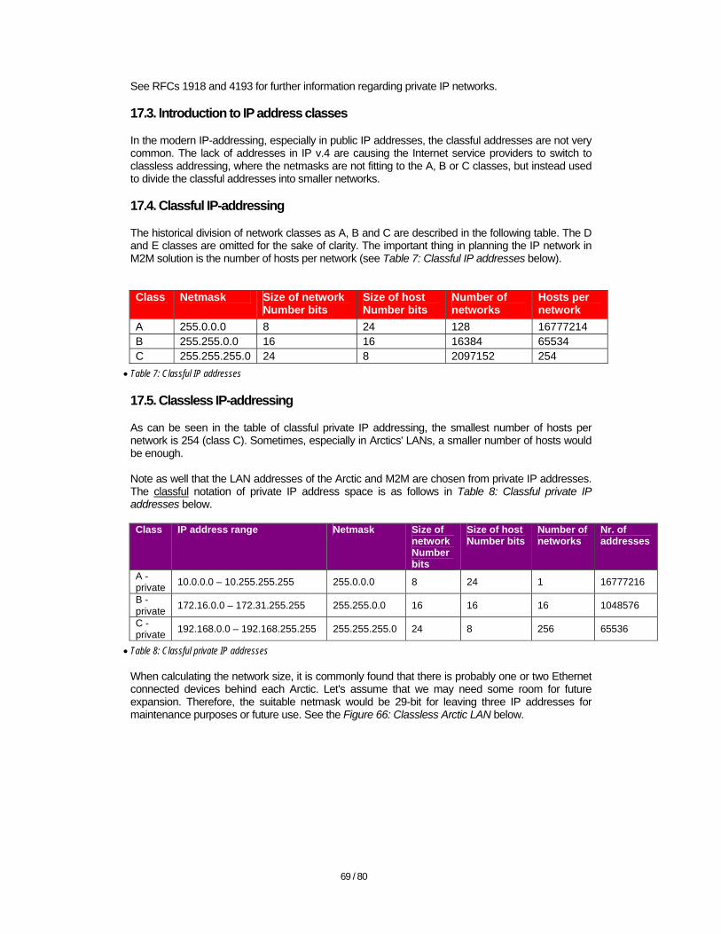
69 / 80
See RFCs 1918 and 4193 for further information regarding private IP networks. 17.3. Introduction to IP address classes
In the modern IP-addressing, especially in public IP addresses, the classful addresses are not very common. The lack of addresses in IP v.4 are causing the Internet service providers to switch to classless addressing, where the netmasks are not fitting to the A, B or C classes, but instead used to divide the classful addresses into smaller networks. 17.4. Classful IP-addressing
The historical division of network classes as A, B and C are described in the following table. The D and E classes are omitted for the sake of clarity. The important thing in planning the IP network in M2M solution is the number of hosts per network (see Table 7: Classful IP addresses below). Class Netmask Size of network
Number bits Size of host Number bits
Number of networks
Hosts per network
A 255.0.0.0 8 24 128 16777214 B 255.255.0.0 16 16 16384 65534 C 255.255.255.0 24 8 2097152 254
• Table 7: Classful IP addresses
17.5. Classless IP-addressing
As can be seen in the table of classful private IP addressing, the smallest number of hosts per network is 254 (class C). Sometimes, especially in Arctics' LANs, a smaller number of hosts would be enough. Note as well that the LAN addresses of the Arctic and M2M are chosen from private IP addresses. The classful notation of private IP address space is as follows in Table 8: Classful private IP addresses below. Class IP address range Netmask Size of
network Number bits
Size of host Number bits
Number of networks
Nr. of addresses
A - private 10.0.0.0 – 10.255.255.255 255.0.0.0 8 24 1 16777216
B - private 172.16.0.0 – 172.31.255.255 255.255.0.0 16 16 16 1048576
C - private 192.168.0.0 – 192.168.255.255 255.255.255.0 24 8 256 65536
• Table 8: Classful private IP addresses
When calculating the network size, it is commonly found that there is probably one or two Ethernet connected devices behind each Arctic. Let's assume that we may need some room for future expansion. Therefore, the suitable netmask would be 29-bit for leaving three IP addresses for maintenance purposes or future use. See the Figure 66: Classless Arctic LAN below.
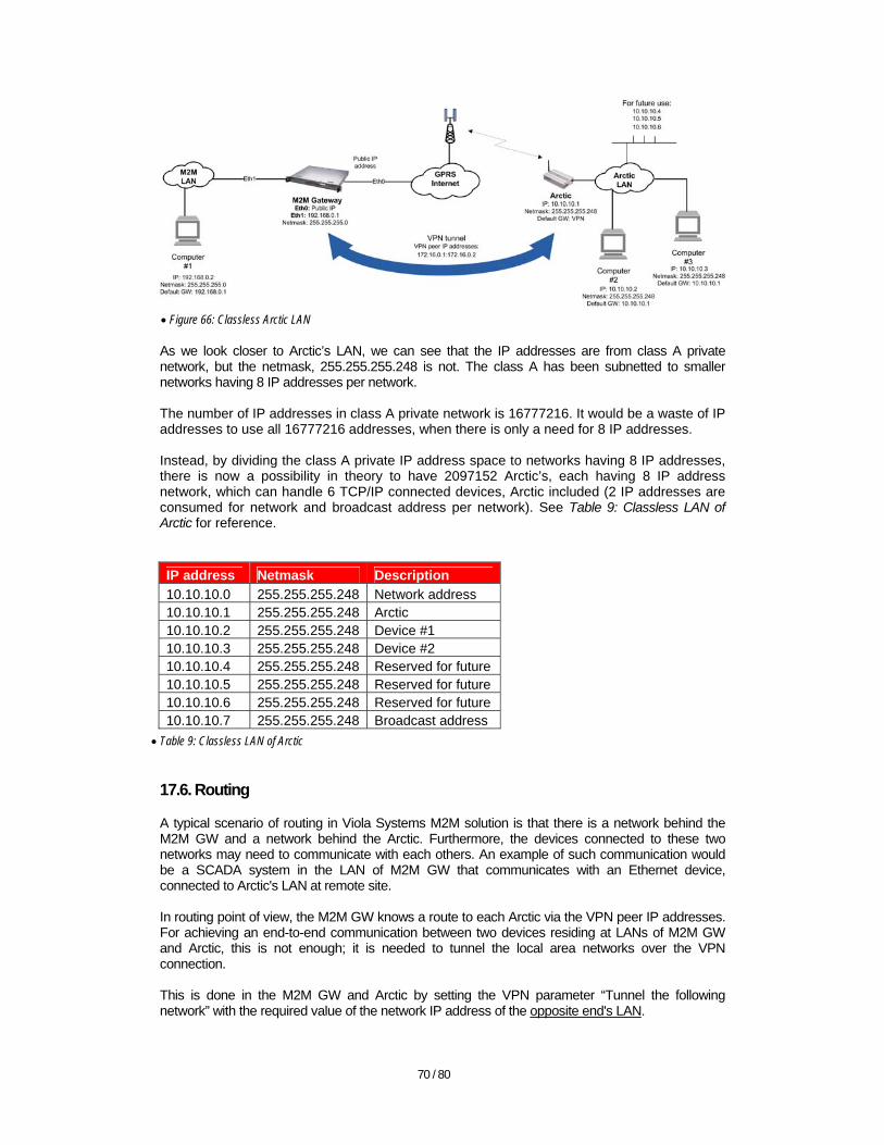
70 / 80
• Figure 66: Classless Arctic LAN
As we look closer to Arctic’s LAN, we can see that the IP addresses are from class A private network, but the netmask, 255.255.255.248 is not. The class A has been subnetted to smaller networks having 8 IP addresses per network. The number of IP addresses in class A private network is 16777216. It would be a waste of IP addresses to use all 16777216 addresses, when there is only a need for 8 IP addresses. Instead, by dividing the class A private IP address space to networks having 8 IP addresses, there is now a possibility in theory to have 2097152 Arctic’s, each having 8 IP address network, which can handle 6 TCP/IP connected devices, Arctic included (2 IP addresses are consumed for network and broadcast address per network). See Table 9: Classless LAN of Arctic for reference. IP address Netmask Description 10.10.10.0 255.255.255.248 Network address 10.10.10.1 255.255.255.248 Arctic 10.10.10.2 255.255.255.248 Device #1 10.10.10.3 255.255.255.248 Device #2 10.10.10.4 255.255.255.248 Reserved for future 10.10.10.5 255.255.255.248 Reserved for future 10.10.10.6 255.255.255.248 Reserved for future 10.10.10.7 255.255.255.248 Broadcast address
• Table 9: Classless LAN of Arctic
17.6. Routing
A typical scenario of routing in Viola Systems M2M solution is that there is a network behind the M2M GW and a network behind the Arctic. Furthermore, the devices connected to these two networks may need to communicate with each others. An example of such communication would be a SCADA system in the LAN of M2M GW that communicates with an Ethernet device, connected to Arctic's LAN at remote site. In routing point of view, the M2M GW knows a route to each Arctic via the VPN peer IP addresses. For achieving an end-to-end communication between two devices residing at LANs of M2M GW and Arctic, this is not enough; it is needed to tunnel the local area networks over the VPN connection. This is done in the M2M GW and Arctic by setting the VPN parameter “Tunnel the following network” with the required value of the network IP address of the opposite end's LAN.

71 / 80
17.7. CIDR, classless inter-domain routing
When there are several classless networks, it may be a tedious task to maintain routing table entries for each individual network. In CIDR routing, a contiguous address space part of several smaller networks is referenced with one routing entry having netmask of a larger network. An example would be networks 10.10.10.0/29, 10.10.10.8/29, 10.10.10.16/29 and 10.10.10.24/29. All of these networks can be referenced with only one CIDR network address with shorter netmask, 10.10.10.0/27. See RFC 1519 for more information on CIDR. 17.8. Network address translation
S-NAT The S-NAT is an acronym for "Source Network Address Translation". The most typical use case for S-NAT is that there is a computer in the Arctic's LAN, which is implemented with private IP addresses. The computer needs to access the Internet, e.g. in order to browse the WWW-pages or to send an email. As the private IP addresses are not routable, they cannot be used for connecting the Internet. Instead, an S-NAT "masquerade" is used. In this technique, the Arctic is hides the intranet LAN IP addresses by converting the source IP addresses from the packets coming from intranet to the public IP address of the Arctic's WAN interface. There may also be an additional S-NAT made by (cellular) network provider. Arctic keeps a table for sending the return-packets coming from Internet back to their original recipient in the intranet. D-NAT The D-NAT is an acronym for "Destination Network Address Translation". A typical case for D-NAT in Arctic is when the private access point of cellular network is used. D-NAT is used to forward packets coming to static IP address of the Arctic's WAN interface to the private IP address of the device connected to the Arctics LAN. Respectively, the S-NAT is used for connections initiated by a host in Arctic's intranet for forwarding them to WAN network. Another example of using D-NAT is when there are overlapping private networks behind several Arctics. In this case, the routing cannot be arranged via Arctics' IP addresses, as they seem to belong to the same network, but in reality they're in different sites having the same private IP addressing. Here the routing cannot be arranged with Arctics' LAN network addresses, but instead the VPN peer addresses of Arctics are used. Each Arctic will then use the D-NAT (in combination with S-NAT) to forward the packets to the proper host in the intranet and vice versa. See RFC-3022 and RFC-4008 for more information on the NAT techniques.
18. Appendix B: Connection establishment
This appendix describes the connection setup between the Arctic and M2M Gateway. In addition the VPN tunnel establishment is described. The dilemma with remote, cellular connected devices is the lack of fixed IP addresses that would be used for connecting the remote device. While private access points from cellular operator are one answer for the problem, they're typically an expensive solution. The Viola M2M solution answers the dilemma by providing fixed IP addresses to the remote devices via VPN tunnel. In addition to that, the Viola M2M solution can work with private access points, adding value in form of proven, ready-made VPN tunneling.
72 / 80
18.1. Scenario 1, public access point with M2M GW
1. Arctic receives an IP address from cellular network. Typically this IP address is a dynamic, private IP address that is S-NATed, while going to the Internet
2. Arctic connects to M2M GW via operator's public access point using the IP address received from cellular network.
3. A VPN tunnel is conformed between the Arctic and M2M GW. 4. Subsequent communication is going through the VPN tunnel.
18.2. Scenario 2, private access point with M2M GW
1. Arctic receives a static IP address from cellular network. 2. Arctic connects via operator's private access point and company's access server to the
M2M GW. 3. A VPN tunnel is conformed between the Arctic and M2M GW. 4. Subsequent communication is going through the VPN tunnel.
18.3. Scenario 3, private access point with Arctics only
1. Two or more Arctics are connected to each others via operator's private access point. 2. Static IP addresses are provided by cellular network. 3. D-NAT and S-NAT are used for routing the packets to devices residing at Arctics' LANs.
19. Appendix C: Acronyms and abbreviations
APN Access point name Baud, Bd Symbols or pulses per second, see BPS. Note that in e.g. modems, the BPS rate may differ from nominal Baud rate because of compressing technologies. BPS Bits per second Browser A program used to view e.g. HTML content (browsing e.g. Internet) CAT5 Category 5 cable (refer to ANSI/EIA-568-A, TSB-95) Certificate In this context, a digital signature of a server for identifying itself with public key. Cross- connected Connecting RX to TX of other device and vice versa DIN Deutsches Institut für Normung (German institute for standardization) EDGE Enhanced data rates for GSM evolution
(http://gsmworld.com/technology/edge.htm) Ethernet Networking technology, (see IEEE 802.3) GPRS General packet radio service GRE Generic routing encapsulation GUI Graphical user interface (see Webmin) HTTP Hypertext transfer protocol HTTPS SSL-protected Hypertext transfer protocol IEC-101 Formerly known as IEC 60870-5-101 IEC-104 Formerly known as IEC 60870-5-104 IP Internet Protocol IP v.4 Internet Protocol version 4, currently used protocol IT Information Technology LAN Local area network Linux An operating system M2M Machine to machine Modbus Serial communications protocol OS Operating system, such as Windows or Linux. Parity Error detecting code, where a change in data is detected PIN Personal identification number Ping, ICMP Internet control message protocol, typically used for sending ping "echo packets" PPP Point to point protocol PSTN Public switched telephone network, “land line”

73 / 80
PUK Personal unblocking key PS/2 In this context: a mini DIN plug containing 6 pins, for connecting a keyboard RX Received data, receiver SCP Secure copy SIM Subscriber identity module SSH Secure shell SSL Secure Sockets layer Sub-D Subminiature D-type connector (typically for connecting analogue VGA monitor) TCP Transmission Control Protocol TCPDUMP A program that captures data packets for concurrent or later analysis TP Twisted pair TUN Tunnel, specifically an OpenVPN tunnel in Viola M2M solution TX Transmitted data, transmitter UDP User datagram protocol URL Universal resource locator (usually known as "web link") USB Universal serial bus UTP Unshielded twisted pair Webmin The graphical user interface of M2M GW VPN Virtual private network WAN Wide area network
20. Appendix D: Viola Systems’ device specific info
Find below a detailed explanation of device-specific features and instructions of parameters and values for initial setup. 20.1. Arctic IEC-104 Gateway
Viola Arctic IEC-104 Gateway offers connectivity for devices of the IEC 60870 protocol family. The IEC-104 is a vendor-independent communication standard for electricity industry. With Arctic IEC-104 Gateway, the conventional IEC-101 serial devices can be attached to a modern TCP/IP based IEC-104 control system. The IEC-104 related settings:
• TX window size (k)
How many IEC-104 packets Arctic sends to IEC-104 master before waiting acknowledgement
• RX window size (w) How many IEC-104 packets Arctic receives from IEC-104 master before sending acknowledgement
• I frames TX timeout (t1) How many seconds to wait acknowledgement from IEC-104 master
• I frames RX timeout (t2) How many seconds to wait from last received IEC-104 packet before sending acknowledgement
• Link test interval (t3) Interval for sending IEC-104 link test packets
• Suspended timeout If the IEC-104 link is on suspended state over defined timeout Arctic will close the link
• Max sequence number Defines the maximum sequence number used on IEC-104 communication
• Cause of transmission length Size of IEC-104 Cause of transmission field length in bytes
• Common address length Size of IEC-104 Common address field length in bytes
• Info object address length Size of IEC-104 Information object address field length in bytes
74 / 80
When configuring the IEC-104 for GPRS connection, one can start with the following values:
• IEC t0 (connection establishment timeout, SCADA only) > 30 secs • IEC t1 (ack rx timeout) = 60 secs • IEC t2 (ack tx timeout) = 20 secs • IEC t3 (link test interval) = 200…600 secs,
SCADA should have approx. 30sec less than arctic • IEC k (tx window size) = 12 • IEC w (rx window size) = 8 • Any completion/control/GI timeout > 60 secs
See Arctic IEC-104 Gateway’s User’s manual for more settings. 20.2. Arctic Modbus Gateway
The Arctic Modbus Gateway offers the following key properties:
• Supports Modbus RTU and Modbus ASCII serial protocols • Supports ModbusTCP, ModbusRTU over TCP, ModbusRTU over UDP, Modbus
ASCII over TCP and Modbus ASCII over UDP network protocols • Can generate and filter out gateway exceptions • Can route traffic on network based on Modbus addressing enabling intelligent use of
network resources • Makes automatic connection management • Enables multiple server sessions over network • Offers unlimited amount of Masters on serial or Network side • Offers 30 routes over network to slaves.
See the Arctic Modbus Gateway specific settings from Arctic Modbus Gateway, Configuration Manual.
21. Appendix E: Troubleshooting
Troubleshooting the solution may sometimes be a difficult task. It is a good practice to divide the solution into smaller subparts, e.g. LAN and WAN connectivity, VPN tunneling, routing, serial connection and so on. 21.1. Troubleshooting principles
• Define the environment – how it should work? Technologies, products, protocols, network design
• Gather the symptoms
– how you see the problem? What is not working, where you can see it?
• Isolate the root cause
– analyze, rule out Follow good troubleshooting practices
• Create a solution
– focus for permanent solution Permanent solution rather than a quick fix
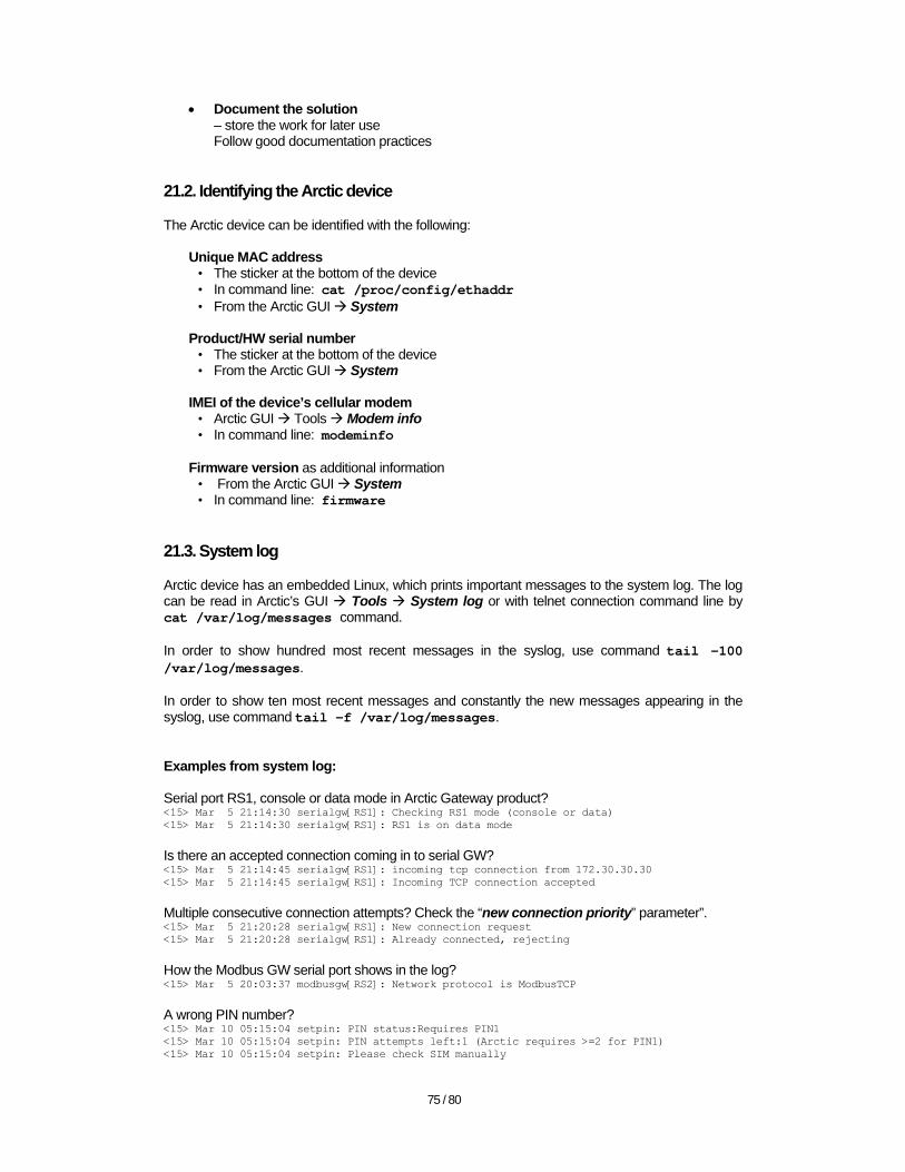
75 / 80
• Document the solution – store the work for later use Follow good documentation practices
21.2. Identifying the Arctic device
The Arctic device can be identified with the following:
Unique MAC address • The sticker at the bottom of the device • In command line: cat /proc/config/ethaddr • From the Arctic GUI System
Product/HW serial number
• The sticker at the bottom of the device • From the Arctic GUI System
IMEI of the device’s cellular modem
• Arctic GUI Tools Modem info • In command line: modeminfo
Firmware version as additional information
• From the Arctic GUI System • In command line: firmware
21.3. System log
Arctic device has an embedded Linux, which prints important messages to the system log. The log can be read in Arctic’s GUI Tools System log or with telnet connection command line by cat /var/log/messages command. In order to show hundred most recent messages in the syslog, use command tail -100 /var/log/messages. In order to show ten most recent messages and constantly the new messages appearing in the syslog, use command tail -f /var/log/messages. Examples from system log: Serial port RS1, console or data mode in Arctic Gateway product? <15> Mar 5 21:14:30 serialgw[RS1]: Checking RS1 mode (console or data) <15> Mar 5 21:14:30 serialgw[RS1]: RS1 is on data mode Is there an accepted connection coming in to serial GW? <15> Mar 5 21:14:45 serialgw[RS1]: incoming tcp connection from 172.30.30.30 <15> Mar 5 21:14:45 serialgw[RS1]: Incoming TCP connection accepted Multiple consecutive connection attempts? Check the “new connection priority” parameter”. <15> Mar 5 21:20:28 serialgw[RS1]: New connection request <15> Mar 5 21:20:28 serialgw[RS1]: Already connected, rejecting
How the Modbus GW serial port shows in the log? <15> Mar 5 20:03:37 modbusgw[RS2]: Network protocol is ModbusTCP A wrong PIN number? <15> Mar 10 05:15:04 setpin: PIN status:Requires PIN1 <15> Mar 10 05:15:04 setpin: PIN attempts left:1 (Arctic requires >=2 for PIN1) <15> Mar 10 05:15:04 setpin: Please check SIM manually

76 / 80
21.4. Contacting Viola Systems Technical support
The Viola Systems Technical Support is able to help with technical problems related to the Viola M2M solution. Before contacting Viola Systems Technical Support, make sure that the following pre-requisites are met:
• The allegedly faulty device has been tested with good troubleshooting practices • There is a list of the problems/findings/faults available • If the problem is network related, a detailed network diagram with IP networking plan is
available • In M2M GW related problems, perform the Viola M2M GW Supportlog gathering (see the
Supportlog icon at the main page of M2M GW’s Webmin GUI) and send the output file to Technical Support. Usually the Arctic’s system log is needed as well.
21.5. Returning a device to Viola Systems
When sending a device back to Viola systems, follow these instructions: Ask the VR (RMA) number beforehand via mailbox [email protected] Enclose the following details:
• Sender’s information • Return address • Type of the device • Serial number of the device • Fault description • Number of devices in the parcel
If not otherwise informed, send the item back to address, (replace the placeholder by received VR number): Viola Systems Ltd. Technical Support / <VR number> Lemminkaisenkatu 14-18 A FI-20520 Turku FINLAND
22. Appendix F: Frequently asked questions
Question 1 The IP-address and netmask are missing in Arctic’s GUI (they cannot be read) and I cannot set them. Answer You have probably set them in arctic> command line with command setenv ipaddr=<IP address>, setenv netmask=<netmask> and saveenv. The problem is that those parameters should be given with space as a separator for parameter and value. Using equal sign (=) as a separator will cause an error in parsing the value. Correct with going to the arctic> command line in serial console connection by hitting any key
77 / 80
within three seconds from Arctic device start, then re-enter the values without equal sign, e.g. as with following commands: setenv ipaddr 10.10.10.10 setenv netmask 255.0.0.0 saveenv boot Question 2 How to restore the Arctic to the factory defaults? Answer There are two methods:
• From the Arctic GUI Tools Default settings • In command line: sh /etc/defaults/setdef.sh
Note that the IP address and netmask are not reverted back to defaults. You can change them to defaults, if needed, by the following commands in arctic> command line (via console): setenv ipaddr 10.10.10.10 setenv netmask 255.0.0.0 saveenv boot Question 3 There is a wrong PIN number entered in Arctic, how to change it? Answer PIN can be changed as follows: Put the SIM card to a mobile phone, enter the correct PIN number, change the PIN number in Arctic’s settings to match the value on SIM card and re-insert the SIM card to Arctic. Question 4 Why the Arctic’s GPRS connection is ended after approximately two minutes? Answer You have enabled connection checking from Network Monitor menu but not set the proper (available) IP address to GPRS “ICMP Echo settings”. Usually it is a good choice to use the M2M GW’s VPN peer IP as a ping target. Question 5 How to check current DNS servers used by Arctic? Answer With the following methods:
• From the Arctic GUI Network Ethernet • In command line: cat /var/run/ppp_resolv.conf
(file exists if the DNS servers are received from the network) • From syslog:
<13> Mar 9 21:10:14 syslog: primary DNS address <IP_address> <13> Mar 9 21:10:14 syslog: secondary DNS address <IP_address>
Question 6 What is the console mode in RS1 interface of Arctic GPRS GW? Answer

78 / 80
In Arctic GPRS gateway, there is a switch that controls the RS1 serial port’s mode. There are two operating modes;
• Console for connecting to Arctic’s command line interface • RS1 for using the port with RS-232 applications
When toggling the console switch, the power of the Arctic must be switched off. The Arctic reads the switch position only at boot. Question 7 Why I’m seeing this error at Arctic boot: JFFS: Failed to build tree. JFFS: Failed to mount device 2a:02. Kernel panic: VFS: Unable to mount root fs on 2a:02 Answer The root file system is corrupted or erased, usually because of failed upgrade attempt. Question 8 Why I’m seeing this error at Arctic boot: arctic> boot Enabling watchdog ## Booting image at ff820000 ... Bad Magic Number arctic>
Answer The system is not able to load the kernel. Again, the message is typically occurring because of failed flash memory upgrade attempt. Question 9 I have accidentally disabled the Web Server in Arctic. Now I cannot connect to the unit via web browser. How can I correct the situation? Answer The WWW-server of the Graphical User Interface in Arctic is implemented with the embedded "Boa web-server". 1. As you have disabled the web server in Arctic’s User Interface, it must first be enabled. If you are able to log in via Telneting to Arctic’s IP address, proceed to step 3. 2. If the IP address of the Arctic is not known, there is a way to connect via serial console. This is done so that you will connect a serial cable (DB9 female connectors, a "null-modem cable") between the PC and Arctic. Then you must check that the Serial port 1 in Arctic is put to "Console" mode by the switch in Arctic’s front panel. Do not change the switch position, while the power is on in the Arctic. When you have the serial connection between the PC (your computer) and Arctic, you can use e.g. PuTTY-terminal emulation program to connect to the Arctic. Alternatively, you can use the HyperTerminal program, which is found in Windows by default. Configure the terminal emulation program as follows, the examples from PuTTY: Click the "Serial" button in the “Session” settings and change the "Speed" from "9600" to "19200". The "Serial line" should match the serial port where the null modem cable is connected to your computer; typically it is "COM1". Now you can click "Open" to open the connection between your computer and Arctic. If you encounter problems with connecting, check the rest of the serial settings by clicking the "Serial" menu-item from the left tab of the Putty Window. The settings should be as follows:

79 / 80
Serial line to connect to: COM1 (or the respective COM-port in your PC) Speed (baud): 19200 Data bits: 8 Stop bits: 1 Parity: None Flow control: None 3. Once you've had the login prompt of the Arctic, enter the username and password. By default, the username is root and password is empty. Next, type "boa &" to the command line as follows: # boa & The operating system will then show a number, which is the process ID number of boa web server that you have just started. 4. If the IP address of the Arctic needs to be changed, follow the Q/A for changing the Arctic’s IP address. 5. Next, you should connect to Arctic with web browser, as usually, and click “Services”. In the opening screen you'll see the Web Server menu item with buttons “Enabled” and “Disabled”. Click the “Enabled” button. Check also that the “Web Configuration Access” is also enabled. If not; click the “Enabled” button for that item as well. Then click Apply and wait until you'll see the text Operations completed successfully and click the “Commit” button in the left part of the screen. Wait until you'll see the text Data files successfully saved. 6. Last, reboot the Arctic so that the new configuration is taken into use.
23. Appendix G: References
Viola Systems Ltd. homepage http://www.violasystems.com Documentation for Viola Systems products http://www.violasystems.com/docs Calculating CIDR routable subnets http://www.subnet-calculator.com/cidr.php Free on-line encyclopedia http://www.en.wikipedia.org Definition for EDGE network http://gsmworld.com/technology/edge.htm RFCs at http://www.ietf.org/rfc.html
• RFC-791 • RFC- 1918, 4193 • RFC-2661 • RFC-3022

80 / 80
• RFC-4008 • RFC-778, 891, 956 , 1305 • RFC-2131 • RFC-1213 • RFC-1157 • RFC-1519
Ethernet specifications: http://www.ieee802.org/3/