Application note Mining Laser alignment in conventional ... · PDF fileLaser alignment in...
8
Mining application – Laser alignment in conventional grinding Introduction In large-scale copper mining, after the process of extracting the ore follows the concentration process. The concentra- tion process releases and concentrates the copper particles held in the form of sulphides in the mineralized rocks so that they can proceed to other stages of the production process. Generally, this process is carried out in large facilities (plant) located near the mine. The concentration process is divided in turn into the following phases: Crushing, Grinding and Flotation. In this particular case we are referring to the grinding phase, whereby the size of the particles making up the mineral is reduced to a grain size of 0,18 mm, which finally enables the release of most of the copper minerals in the form of individual particles. The grinding process is performed using large cylindrical rotating machines, or mills, in two forms: conventional mills and SAG mills. In this stage, moreover, the mineralized material has water added to it in sufficient quantity to form a milk-like fluid and the reagents needed for the next process. Alignment application note Figure 1: Copper processing plant Figure 2: Rod mill (internal view) Figure 3: Ball mill (internal view) Figure 4: Ball mill (external view) Conventional milling: Carried out in two stages using rod mills and ball mills (some plants only use ball mills). The rod mill has 89 mm diameter steel rods inside it which are what do the grinding. The ball mill has 35% of its capacity taken up by 89 mm diameter steel balls, which do the grinding.
Transcript of Application note Mining Laser alignment in conventional ... · PDF fileLaser alignment in...

Mining application – Laser alignment in conventional grinding
IntroductionIn large-scale copper mining, after the process of extracting the ore follows the concentration process. The concentra-tion process releases and concentrates the copper particles held in the form of sulphides in the mineralized rocks so that they can proceed to other stages of the production process. Generally, this process is carried out in large facilities (plant) located near the mine. The concentration process is divided in turn into the following phases: Crushing, Grinding and Flotation.In this particular case we are referring to the grinding phase, whereby the size of the particles making up the mineral is reduced to a grain size of 0,18 mm, which finally enables the release of most of the copper minerals in the form of individual particles. The grinding process is performed using large cylindrical rotating machines, or mills, in two forms: conventional mills and SAG mills. In this stage, moreover, the mineralized material has water added to it in sufficient quantity to form a milk-like fluid and the reagents needed for the next process.
Alignment application note
Figure 1: Copper processing plant
Figure 2: Rod mill (internal view)
Figure 3: Ball mill (internal view)
Figure 4: Ball mill (external view)
Conventional milling: Carried out in two stages using rod mills and ball mills (some plants only use ball mills). The rod mill has 89 mm diameter steel rods inside it which are what do the grinding. The ball mill has 35% of its capacity taken up by 89 mm diameter steel balls, which do the grinding.

Mining application: Laser alignment in conventional grinding – page 2
ApplicationThe alignment of the mills’ drive trains is a very important matter from the production point of view. Due to the high costs from down times, the time spent on maintenance tasks for these units must be reduced to a minimum. The application in question for this technical report was applied to a ball mill in a grinding plant in an underground mine located in Chile’s Central Cordillera. The client requested a laser alignment service after maintenance work was done on the assembly’s final driveshaft bearings. To illustrate these applications, we shall refer to other grinding mill configura-tions we have found in our years of service in this type of industry.Historically, these units were aligned using the dial gauge method and the work could take from around 10 hours to more than 15 hours for each mill. Another problem is that there is no certainty around the quality of the work done using dial gauges when one considers that the environment is noisy, dark and very dusty. It is easy to imagine the high production losses arising from having stopped one of these units just for alignment.
Description of the machineBall mills drive trains may have different configurations but the most common ones are described below. Each of the configurations shown presents different problems and chal-lenges, as can be seen in the next three cases.
Case No. 1
Case No.1 shows a motor coupled by means of a semi-rigid junction to a transverse reduction gear which is coupled by means of a flexible coupling to a two-bearing final drive- shaft with the pinion that rotates the mill. When the coupling between the gearbox output shaft and the final drive-shaft is disconnected, this makes it possible to simultaneously rotate the motor output shaft and gearbox input shaft. The final drive-shaft cannot be rotated due to the weight of the mill.
Figure 6: Motor / clutch / final drive-shaft with pinion to the mill
Case No. 2
Figure 7: Motor / clutch / intermediate shaft / flexible coupling / final drive-shaft with pinion to the mill
Case No. 2 shows a motor connected using a clutch to a final two-bearing drive-shaft in the location of the pinion that moves the mill. The clutch gives independent freedom of movement to both shafts (motor shaft and final drive- shaft). Sometimes, the clutch will end in a tapered shaft to the motor. The final drive-shaft cannot be rotated due to the weight of the mill. Moreover, due to the fact that the angle between the drive shaft pinion and the mill pinion is deter-mined by the manufacturer to ensure correct lubrication, it is not possible to change the position of the drive-shaft bearings.
Case No. 3
Figure 5: Motor / flexible coupling / reduction gear / flexible coupling / final drive-shaft with pinion to the mill
Case No. 3 shows a motor coupled by means of a semi-rigid connector to a transverse reduction gear which is coupled by means of a flexible coupling to a two-bearing final drive-shaft with the pinion that moves the mill. When the coupling between the gear box output shaft and the final drive-shaft is disconnected, this makes it possible to simultaneously rotate the motor output shaft and gearbox input shaft.
Moreover, due to the fact that the angle between the drive shaft pinion and the mill pinion is determined by the manu-facturer to ensure correct lubrication, it is not possible to change the position of the drive-shaft bearings.

Mining application: Laser alignment in conventional grinding – page 3
ProcedureTo carry out alignment in the most efficient way from the time point of view, preparation of the machine must be carried out in advance (checking fasteners, disconnecting couplings, checking shims, etc).
Thought must be given to the possible problems likely to be encountered and the best solution to solve them with the tools that the laser alignment kit can provide.Let us return to the three cases described above:
Case No. 1Motor / flexible coupling / reduction gear / flexible coupling / final drive-shaft with pinion to the mill (Fig. 5)In this case the alignment has to be done in two steps. First the drive-shaft - reduction gear alignment (alignment A) must be done and then the reduction gear – motor alignment (alignment B). The difficulty is that the final drive-shaft cannot rotate. It was decided that for alignment A the final drive-shaft would be stationary machine, as it must not be moved on account of the pinion angle. The reduction gear would be the machine to be moved. For alignment B the reduction gear would be the reference and the motor would be the machine to be moved.Configuration, mounting and measuring:A three-machine configuration (Fig. 9) is made: for alignment A the final drive-shaft is the static machine and the reduction gear is the one to be moved, with 4, 6 or 8 feet, depending on its configuration and position.
Figure 8: Coordination and preparation
Once again, considering that the pinion angle must be adjusted for correct lubrication (which must not be modified) this means the final drive-shaft cannot be turned (or the entire mill has to be rotated) and it is not possible to change the position of the drive-shaft bearings.
For alignment B the reduction gear would be stationary and the motor would be the machine to be moved (2 pair of feet). The type of coupling is selected, what determines the tolerances according to the RPM and the coupling diameter.
Figure 9: Machine train dimensions screen
For alignment A, the laser is mounted using the magnetic sliding bracket on the final drive-shaft. The brackets are mounted on the outer or inner face of the shaft. The sensor is mounted with the standard chain-type brackets on the gearbox output shaft.For alignment B, laser and sensor are mounted using standard chain-type brackets on both the gearbox input shaft and the motor shaft.Firstly, soft foot is measured and then corrected.For measuring alignment A, the coupling between the motor and the gearbox input shaft must be disconnected in order to allow the gearbox output shaft to rotate. The readings are taken with “Multipoint” mode (Fig. 10) taking more than 8 points for each measurement. Several measurements are taken in the same direction and if the values are somehow repeatable, then these can be averaged. Besides that, it is recommended to increase the measurement averaging filter before starting taking data.
Figure 10: Multipoint measurement mode screen

Mining application: Laser alignment in conventional grinding – page 4
For measuring alignment B, the coupling between the final drive-shaft and the gearbox output shaft must be discon-nected in order to allow the gearbox input shaft to rotate. The readings are taken in “Continuous Sweep” mode (Fig. 11), which considers the best 128 points for the calculation of the ellipse. In many cases in these mill configurations there will be an auxiliary motor which drives the reduction gear and makes rotation possible.
For both alignment jobs (A and B) the correction and final adjustment were done using the “Live Move” function, which enables real-time simultaneous monitoring of both horizontal and vertical planes on just one screen. The Live move allows to considerably reducing the time taken for correction. Finally, once correction is complete, a final measurement is taken to ensure that “excellent” tolerances have been achieved.
Figure 11: Continuous measurement mode screen
ResultsFigure 12 shows the results achieved before final adjust-ments and subsequent check measurements for a mill (Case No. 3).
Figure 12: Results screen: Machine train and tolerances (Case No. 3)
The representation of the machine train in both planes (hori-zontal and vertical) can be clearly seen with all the tolerance data, values for the four parameters and foot correction values.It is important that plant maintenance staff obtain the reports and records provided by the equipment and/or ALIGNMENT CENTER software.By using laser alignment systems the time taken to work on these milling units is normally reduced to a maximum of 2 to 4 hours (from starting alignment to handover for operation) depending on the configuration of the assembly, availability of shims and coordination of staff for moving machines.
The alignment of the machines in cases 2 and 3 is similar to case 1. A short summary is described in the following lines.
Case No. 2Motor / clutch / final drive-shaft with pinion to the millIn this case final drive-shaft has to be aligned to the motor assembly, where the final drive shaft cannot rotate and the clutch normally has a large diameter. It has been decided that the motor will be the machine to be moved -MTBM- and the final drive-shaft the reference one. Another reason for this decision is that the final drive-shaft can’t be moved in order not to change the contact angle to the pinion.Configuration, mounting and measuring:The configuration is defined with the motor as the machine to be moved (4 feet) and final drive-shaft as the reference one. The type of coupling, RPM and coupling diameter determine the tolerances. The corresponding parameters are selected according to the described configuration.The sensor is mounted using brackets with long posts on the motor shaft, due to the big clutch diameter. On the final drive-shaft the magnetic sliding bracket is used to mount the laser (sometimes it is mounted outside and other times even on the shaft’s inner face when the clutch is disconnected).First of all soft foot is measured and then corrected.To check the alignment condition readings are taken in “multi-point” mode taking more than 8 points per measure-ment. Several measurements are taken so that in case of getting a good repeatability, these can be averaged.It is recommended to increase the averaging filter for taking data, as such mills are normally located together with other similar units in the same building. Vibrations generated by the other machines can influence the measurement. Then, the next step is to proceed with the corrections. The final adjustment is done with the “move” function which enables real-time simultaneous monitoring of both horizontal and vertical planes on just one screen. This function considerably

Mining application: Laser alignment in conventional grinding – page 5
Case No. 3Motor / clutch / intermediate shaft / flexible coupling / final drive-shaft with pinion to the millIn this case the alignment must be done in two steps. The first step is the alignment of the final drive-shaft - intermediate shaft alignment (alignment A). The second alignment part is between the intermediate shaft and the motor (alignment B). In this last case, the final drive-shaft cannot rotate and the clutch normally has a large diameter. It was decided that for alignment A the final drive-shaft is the static machine. The reason is to avoid changing its angle to the pinion. The intermediate shaft is the one to be moved. For alignment B the intermediate shaft is the static machine and the motor is the machine to be moved.Configuration, mounting and measuring:For this case a three-machine configuration is made: for alignment A the final drive-shaft is the static machine and the intermediate shaft is the machine to be moved (2 pairs of feet). For alignment B the intermediate shaft is the reference machine and the motor is the machine to be moved (4 feet). The type of coupling, its diameter and RPM are entered, thus determining the tolerances for the alignment job. For alignment A the laser is mounted using the magnetic sliding bracket on the final drive-shaft. Sometimes it is mounted outside and on other occasions in the inner face of the shaft. The sensor is mounted on standard chain brackets on the intermediate shaft.
Figure 13: Aligning a ball mill
Figure 14: Aligning a ball mill – mounting sensor
For alignment B, the laser is mounted using standard chain brackets or magnetic brackets as necessary on the intermedi-ate shaft. The sensor is mounted on standard chain brackets with long posts on the motor shaft. The long posts allow the laser beam to overcome the clutch big diameter.Once everything is mounted, soft foot is measured and then corrected.For measurement of alignment A, the coupling between the motor and the intermediate shaft must be disconnected to enable the intermediate shaft to rotate. Readings are taken with “multi-point” mode thus enabling more than 8 points to be taken for each measurement. Several measurements in the same rotating direction are taken. If the results show repeatability, these can be averaged. It is recommended to increase the measurement average filter before taking data.To measure alignment B, the coupling between the final drive-shaft and the intermediate shaft must be disconnected to enable the intermediate shaft to rotate. Readings are taken in “continuous sweep” mode.For both alignments (A and B) the “Live move” function is used for correction and final adjustment. This function allows real-time simultaneous monitoring of both horizontal and vertical planes on just one screen. This considerably reduces the time taken for correction. Finally, once correc-tion is complete, a final measurement is taken to ensure that “excellent” tolerances have been achieved. After this it is possible to see the aligned condition of the entire drive train (3 machines).
reduces the time taken for correction. Finally, once correction is complete, a final condition check is performed to ensure that “excellent” tolerances have been achieved.

Mining application: Laser alignment in conventional grinding – page 6
Some important points to consider: � The procedures described can vary considerably from one mill to the next depending on the particular cir-cumstances, spaces available for mounting, quality of components and the extent to which each individual part of an assembly can rotate.
� When dealing with large diameter couplings and clutches, it is possible, thanks to the single-laser technology, to direct the laser beam through a bolt hole on the coupling, thus avoiding raising the laser and sensor.
� The intermediate shafts and final drive-shafts normally have plummer blocks where it is advisable to check the alignment of the blocks to each other (bore alignment). Furthermore, attention has to be paid to possible assisted shaft lubrication when it is operated, which must be taken into account if present.
� Occasionally, long posts have to be used to mount the sensors; it is advisable to use original posts, not self-made for this purpose, as well as anti-torsion bridges, if available.
� In some cases, for a final drive-shaft-motor alignment when the final drive-shaft cannot be rotated, “pass” mode must be used with the magnetic sliding bracket: when faced with this situation it is important to clarify that the receiver must be on the magnetic sliding bracket on the shaft of the static machine (the final drive-shaft). In this scenario the instrument configuration will be as shown in Fig. 15.
Figure 15: Dimensions screens showing the ‘Static foot’ function
The assembly must be configured with the final drive-shaft as the machine on the right (where the receiver is located) and the motor is the machine to the left (where the laser is located). Then the “static foot” function is used to fix the final drive-shaft feet and have the motor feet as movable (see Fig. 16).
Figure 16: Dimensions and results screens. Static feet function allows motor movement on the left side
� If alignment is taking place after a repair, it is likely that the “extend” function will need to be used to take measurements when misalignment is severe.
� To facilitate work and reduce the time needed to suc-cessfully complete it, machine preparation and staff coordination for movements and having all necessary tools and shims should be done.
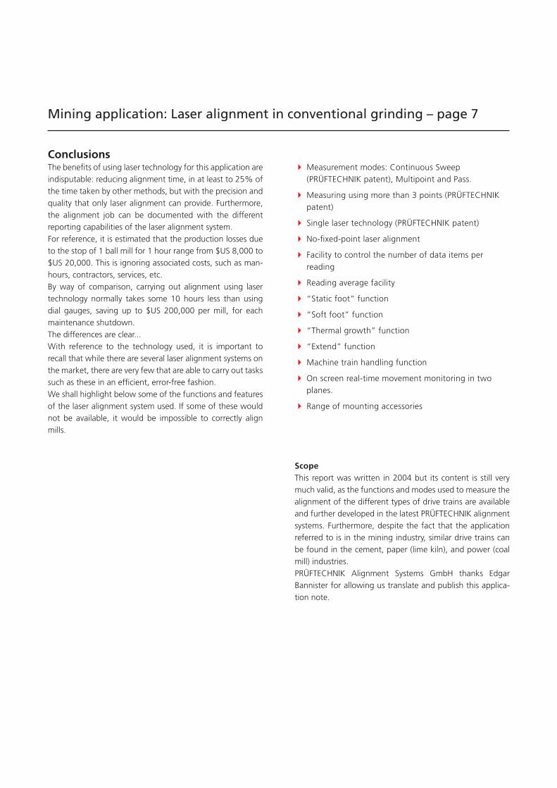
� Measurement modes: Continuous Sweep (PRÜFTECHNIK patent), Multipoint and Pass.
� Measuring using more than 3 points (PRÜFTECHNIK patent)
� Single laser technology (PRÜFTECHNIK patent)
� No-fixed-point laser alignment
� Facility to control the number of data items per reading
� Reading average facility
� “Static foot” function
� “Soft foot” function
� “Thermal growth” function
� “Extend” function
� Machine train handling function
� On screen real-time movement monitoring in two planes.
� Range of mounting accessories
ConclusionsThe benefits of using laser technology for this application are indisputable: reducing alignment time, in at least to 25% of the time taken by other methods, but with the precision and quality that only laser alignment can provide. Furthermore, the alignment job can be documented with the different reporting capabilities of the laser alignment system.For reference, it is estimated that the production losses due to the stop of 1 ball mill for 1 hour range from $US 8,000 to $US 20,000. This is ignoring associated costs, such as man-hours, contractors, services, etc.By way of comparison, carrying out alignment using laser technology normally takes some 10 hours less than using dial gauges, saving up to $US 200,000 per mill, for each maintenance shutdown.The differences are clear...With reference to the technology used, it is important to recall that while there are several laser alignment systems on the market, there are very few that are able to carry out tasks such as these in an efficient, error-free fashion.We shall highlight below some of the functions and features of the laser alignment system used. If some of these would not be available, it would be impossible to correctly align mills.
ScopeThis report was written in 2004 but its content is still very much valid, as the functions and modes used to measure the alignment of the different types of drive trains are available and further developed in the latest PRÜFTECHNIK alignment systems. Furthermore, despite the fact that the application referred to is in the mining industry, similar drive trains can be found in the cement, paper (lime kiln), and power (coal mill) industries.PRÜFTECHNIK Alignment Systems GmbH thanks Edgar Bannister for allowing us translate and publish this applica-tion note.
Mining application: Laser alignment in conventional grinding – page 7
Productive maintenance technologyA member of the PRÜFTECHNIK Group
PRÜFTECHNIK Alignment Systems GmbHFreisinger Str. 3485737 IsmaningGermanyTel +49 89 99616-0Fax +49 89 [email protected]
P R O V E N Q U A L I T Y
Made in Germany
Global Presence
Qualified Support
Quality Service
Mining application: Laser alignment in conventional grinding – page 8
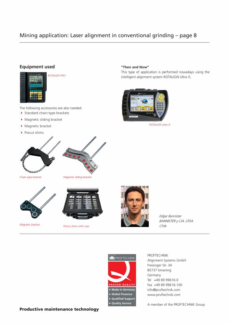
Edgar BannisterBANNISTER y CIA. LTDAChile
ROTALIGN PRO
Equipment used
ROTALIGN Ultra iS
The following accessories are also needed: � Standard chain-type brackets
� Magnetic sliding bracket
� Magnetic bracket
� Precut shims
Chain type bracket Magnetic sliding bracket
Magnetic bracketPrecut shims with case
“Then and Now”This type of application is performed nowadays using the intelligent alignment system ROTALIGN Ultra iS.