Application Note Debug Cable TriCore - Lauterbach · Application Note Debug Cable TriCore 6...
51
Application Note Debug Cable TriCore 1 ©1989-2018 Lauterbach GmbH Application Note Debug Cable TriCore TRACE32 Online Help TRACE32 Directory TRACE32 Index TRACE32 Documents ...................................................................................................................... ICD In-Circuit Debugger ................................................................................................................ Processor Architecture Manuals .............................................................................................. TriCore ...................................................................................................................................... TriCore Application Notes ................................................................................................... Application Note Debug Cable TriCore ........................................................................... 1 Introduction .................................................................................................................... 4 Debug Protocols ............................................................................................................. 5 JTAG 5 Multi-Chip Debugging (Daisy-Chaining Multiple TAP Controllers) 5 Enabling JTAG on TriCore Devices 6 DAP 6 DAP Over Dedicated Pins 6 DAP over CAN 7 Connector Standards and Signals ................................................................................ 8 Description of Signals 8 OCDS-L1 Connector 10 Automotive Debug Connector 11 CAN D-Sub Connector 12 Custom Connectors 13 MEDC17 13 ECU14 13 ECU14 Connector Signals and Pin Assignment for JTAG 14 ECU14 Connector Signals and Pin Assignment for DAP 14 Trace Connectors 14 Debug Cables ................................................................................................................. 16 OCDS Debug Cables 18 Unidirectional Cables 18 OCDS Uni-Dir Debug Cable V0 18 OCDS Uni-Dir Debug Cable V1 19 Electrical Characteristics 20 Bidirectional OCDS Debug Cables 20 OCDS Bi-Dir Debug Cables V1 and V2 20
-
Upload
nguyenxuyen -
Category
Documents
-
view
293 -
download
3
Transcript of Application Note Debug Cable TriCore - Lauterbach · Application Note Debug Cable TriCore 6...

Application Note Debug Cable TriCore
TRACE32 Online Help
TRACE32 Directory
TRACE32 Index
TRACE32 Documents ......................................................................................................................
ICD In-Circuit Debugger ................................................................................................................
Processor Architecture Manuals ..............................................................................................
TriCore ......................................................................................................................................
TriCore Application Notes ...................................................................................................
Application Note Debug Cable TriCore ........................................................................... 1
Introduction .................................................................................................................... 4
Debug Protocols ............................................................................................................. 5
JTAG 5
Multi-Chip Debugging (Daisy-Chaining Multiple TAP Controllers) 5
Enabling JTAG on TriCore Devices 6
DAP 6
DAP Over Dedicated Pins 6
DAP over CAN 7
Connector Standards and Signals ................................................................................ 8
Description of Signals 8
OCDS-L1 Connector 10
Automotive Debug Connector 11
CAN D-Sub Connector 12
Custom Connectors 13
MEDC17 13
ECU14 13
ECU14 Connector Signals and Pin Assignment for JTAG 14
ECU14 Connector Signals and Pin Assignment for DAP 14
Trace Connectors 14
Debug Cables ................................................................................................................. 16
OCDS Debug Cables 18
Unidirectional Cables 18
OCDS Uni-Dir Debug Cable V0 18
OCDS Uni-Dir Debug Cable V1 19
Electrical Characteristics 20
Bidirectional OCDS Debug Cables 20
OCDS Bi-Dir Debug Cables V1 and V2 20
Application Note Debug Cable TriCore 1 ©1989-2018 Lauterbach GmbH

OCDS Bi-Dir Debug Cable V3, V4 21
Electrical Characteristics 22
Automotive Debug Cables 24
Automotive Debug Cable
Automotive-Pro Debug Cable
Debug Interface Configuration ...................................................................................... 27
Connecting using DAP over Dedicated Pins 27
Example Connection Script 28
Connecting using JTAG 28
Connecting using DXCPL/DXCM with DXCPL Box 29
Sharing the Debug Port between TRACE32 and 3rd-Party Tool 31
DAP User Pins 31
Break Pins 32
Controlling an External Watchdog 33
Adapters, Converters and Extensions ......................................................................... 34
Adapter 16-pin 100 mil to 50 mil 34
Converter 16-pin JTAG to DAP for TriCore/XC2000/XC800 35
Converter DXCPL Box for TriCore 36
Converter 16-pin JTAG to BOSCH MEDC17 for TriCore 37
Converter AUTO26/ OnCE14-PPC/ JTAG16-TC to ECU14 37
Converter AUTO26 to ECU14 38
Converter JTAG16-TriCore to AUTO26 39
Converter AUTO26 to JTAG16-TriCore 39
Converter Samtec 60 to AMP 40 40
Converter 16-pin OCDS-L1 to Samtec 60 for TriCore 40
Converter 16-pin OCDS-L1/ 40-pin HSSTP to ERF8 for TriCore 41
Converter OCDS-L1/ AUTO26/ PowerTrace Serial to ERF8 for TriCore 42
Flex Extension for SAMTEC 60-pin QTH-QSH series 42
Flex Extension for SAMTEC 60-pin QTH-QSH series 43
Cable 26-pin for Automotive Debug Cables 44
Cable 20-pin for Automotive Debug Cables 44
Cable 10-pin for Automotive Debug Cables 45
Recommended Connectors ........................................................................................... 46
Standard 2x8 Connector 46
Half-size 2x8 Connector 46
Half-size 2x5 Connector 47
Half-size 2x5 Connector with Keying Pin 7 47
Half-size 2x10 Connector with Keying Pin 7 48
Half-size 2x13 Connector with Keying Pin 7 49
TFM 2x5 Connector 50
AMP 40 Connector 50
ERF8 22-pin Power.org Connector 51
Application Note Debug Cable TriCore 2 ©1989-2018 Lauterbach GmbH

Samtec 60 Connector 51
Application Note Debug Cable TriCore 3 ©1989-2018 Lauterbach GmbH

Application Note Debug Cable TriCore
Version 16-Nov-2018
Introduction
This application note provides information about the Lauterbach debug cables supporting the Infineon TriCore devices, the associated debug protocols and a description of their signals and how to connect the signals.
In addition, this document lists the different target connectors, including their order codes. The adapters and converters required for connecting the debug cable to the various target connectors are also described, including order information.
The information of this application note can be used in two ways: Learn more about the debug cables and debug connectors already in use, and decide what is most suitable for the next project.
For additional information about the TriCore debugger consult “TriCore Debugger and Trace” (debugger_tricore.pdf), as well as the device documentation available from Infineon. This is especially important for finding out which debug protocols are supported by the device.
This document assumes that you are already familiar with the basics of the TriCore architecture, your TriCore device and the TRACE32 debugger. Please refer to the Infineon TriCore and Lauterbach TRACE32 documentation if necessary.
This application note does not cover the following topics:
• The USB-Over-Emulation-Device connection via a USB cable. This is only available for TriCore TC1766ED and TC1796ED and discontinued today.
• Information on the off-chip trace interfaces and the trace preprocessors.
• Licensing information.
Application Note Debug Cable TriCore 4 ©1989-2018 Lauterbach GmbH
Debug Protocols
This chapter introduces the debug protocols available for Infineon TriCore devices, JTAG and DAP as well as their different implementations. More details about the associated connectors can be found in chapter “Connector Standards and Signals”, page 8. More details on the different debug cables can be found in “Debug Cables”, page 16.
JTAG
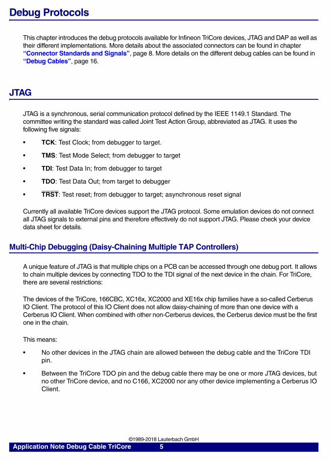
JTAG is a synchronous, serial communication protocol defined by the IEEE 1149.1 Standard. The committee writing the standard was called Joint Test Action Group, abbreviated as JTAG. It uses the following five signals:
• TCK: Test Clock; from debugger to target.
• TMS: Test Mode Select; from debugger to target
• TDI: Test Data In; from debugger to target
• TDO: Test Data Out; from target to debugger
• TRST: Test reset; from debugger to target; asynchronous reset signal
Currently all available TriCore devices support the JTAG protocol. Some emulation devices do not connect all JTAG signals to external pins and therefore effectively do not support JTAG. Please check your device data sheet for details.
Multi-Chip Debugging (Daisy-Chaining Multiple TAP Controllers)
A unique feature of JTAG is that multiple chips on a PCB can be accessed through one debug port. It allows to chain multiple devices by connecting TDO to the TDI signal of the next device in the chain. For TriCore, there are several restrictions:
The devices of the TriCore, 166CBC, XC16x, XC2000 and XE16x chip families have a so-called Cerberus IO Client. The protocol of this IO Client does not allow daisy-chaining of more than one device with a Cerberus IO Client. When combined with other non-Cerberus devices, the Cerberus device must be the first one in the chain.
This means:
• No other devices in the JTAG chain are allowed between the debug cable and the TriCore TDI pin.
• Between the TriCore TDO pin and the debug cable there may be one or more JTAG devices, but no other TriCore device, and no C166, XC2000 nor any other device implementing a Cerberus IO Client.
Application Note Debug Cable TriCore 5 ©1989-2018 Lauterbach GmbH

Enabling JTAG on TriCore Devices
Current TriCore devices (e.g., the AUDO-MAX or AURIX family) support different debug protocols. The used protocol is determined by the value of TRST at the time RESET was released. Such a device will be in JTAG mode if one of the following conditions is met:
• TRST was low at the time RESET was released and is now high.
• TRST was high at the time RESET was released and a special sequence was sent on TMS. (Only supported by AURIX family and newer devices)
By default TRACE32 will use the first method where possible. Special configuration might be required if TRST cannot be controlled by TRACE32. For details see “Using JTAG with 10-pin Automotive Debug Connector”, page 28.
DAP
DAP (Device Access Port) is a telegram-based communication protocol promoted by Infineon. The protocol is tailored to the needs of debugging TriCore devices. In contrast to JTAG, all telegrams include a checksum (CRC) to ensure the correctness of the transferred telegrams and so allows to detect transmission errors and connection losses. Because of that we recommend to use DAP whenever possible.
DAP telegrams can be send and received using different electrical interfaces which are described in the following.
DAP Over Dedicated Pins
Typically, DAP is connected to the TriCore device using dedicated pins. These pins are usually a subset of the pins used for JTAG. Depending on the device, the following modes are available:
• DAP2: This mode uses one clock line (DAP0) and one bidirectional data line (DAP1).
• DAP3: This mode uses one clock line (DAP0), and two unidirectional data lines (DAP1 and DAP2). DAP1 carries the data from the debugger to the target and DAP2 carries the data from the target to the debugger.
• DAPWide: This mode uses one clock line (DAP0), and two bidirectional data lines (DAP1 and DAP2).
Enabling on TriCore Devices
A TriCore device will be in DAP mode if TRST was high at the time RESET was released. This can be either achieved by:
• An appropriate pull-up on the board,
• Connect to the DAPDIR pin of your debug connector,
• Connect to the DAPEN pin of your debug connector and configure it according to “Debug Interface Configuration”, page 27.
Application Note Debug Cable TriCore 6 ©1989-2018 Lauterbach GmbH
For AURIX and newer devices, the DAP mode will be configured automatically by TRACE32 by sending an appropriate initialization sequence. Older devices start with the DAP2 mode by default.
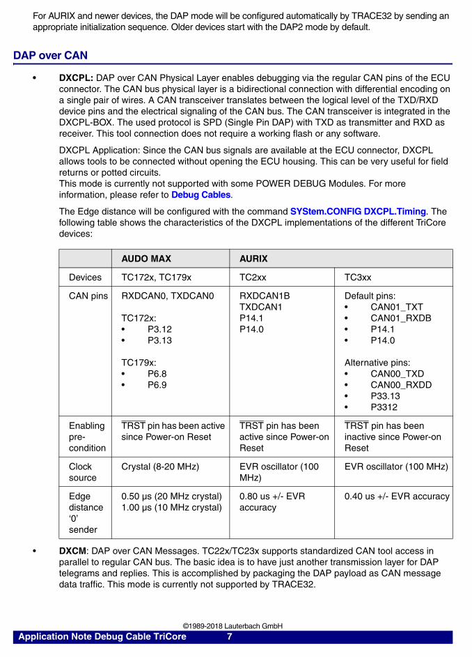
DAP over CAN
• DXCPL: DAP over CAN Physical Layer enables debugging via the regular CAN pins of the ECU connector. The CAN bus physical layer is a bidirectional connection with differential encoding on a single pair of wires. A CAN transceiver translates between the logical level of the TXD/RXD device pins and the electrical signaling of the CAN bus. The CAN transceiver is integrated in the DXCPL-BOX. The used protocol is SPD (Single Pin DAP) with TXD as transmitter and RXD as receiver. This tool connection does not require a working flash or any software.
DXCPL Application: Since the CAN bus signals are available at the ECU connector, DXCPL allows tools to be connected without opening the ECU housing. This can be very useful for field returns or potted circuits.This mode is currently not supported with some POWER DEBUG Modules. For more information, please refer to Debug Cables.
The Edge distance will be configured with the command SYStem.CONFIG DXCPL.Timing. The following table shows the characteristics of the DXCPL implementations of the different TriCore devices:
• DXCM: DAP over CAN Messages. TC22x/TC23x supports standardized CAN tool access in parallel to regular CAN bus. The basic idea is to have just another transmission layer for DAP telegrams and replies. This is accomplished by packaging the DAP payload as CAN message data traffic. This mode is currently not supported by TRACE32.
AUDO MAX AURIX
Devices TC172x, TC179x TC2xx TC3xx
CAN pins RXDCAN0, TXDCAN0
TC172x: • P3.12• P3.13
TC179x: • P6.8• P6.9
RXDCAN1B TXDCAN1P14.1P14.0
Default pins:• CAN01_TXT• CAN01_RXDB• P14.1• P14.0
Alternative pins:• CAN00_TXD• CAN00_RXDD• P33.13• P3312
Enabling pre-condition
TRST pin has been active since Power-on Reset
TRST pin has been active since Power-on Reset
TRST pin has been inactive since Power-on Reset
Clock source
Crystal (8-20 MHz) EVR oscillator (100 MHz)
EVR oscillator (100 MHz)
Edge distance ‘0’ sender
0.50 µs (20 MHz crystal)1.00 µs (10 MHz crystal)
0.80 us +/- EVR accuracy
0.40 us +/- EVR accuracy
Application Note Debug Cable TriCore 7 ©1989-2018 Lauterbach GmbH

Connector Standards and Signals
TRACE32 supports a a variety of connector standards for connecting the debugger to the target device. Each connector supports one or more debug protocols.
Description of Signals
In the following the signal names used in the remainder of this chapter are described. The following signal types are distinguished:
• output: driven by the debugger, received by the target
• input: driven by the target, received by the debugger
Connector type Pin count Protocols Target connector
OCDS-L1 16-pin Debug: JTAG, DAPsupport for ETK
Standard 2x8
DAP 10-pin Debug: DAP Half-size 2x5
MEDC17 10-pin Debug: JTAG Half-size 2x5
ECU14 10-pin Debug: JTAG TFM 2x5
AUTO-26 26-pin Debug: JTAG, DAPsupport for ETK
Half-size 2x13, pin 7 is key
AUTO-20 20-pin Debug: JTAG, DAP Half-size 2x10, pin 7 is key
AUTO-10 10-pin Debug: JTAG (no TRST), DAP
Half-size 2x5, pin 7 is key
OCDS-L2 40-pin Trace: OCDS-L2 AMP 40
OCDS-L2 60-pin Debug: JTAGTrace: OCDS-L2
Samtec 60
ERF8(Power.org)
22-pin Debug: JTAG, DAPTrace: AGBT
ERF8 22
Application Note Debug Cable TriCore 8 ©1989-2018 Lauterbach GmbH

Signal Name Description Recommendations
VTREF(input)
Reference VoltageThe pin is used to detect if target power is on and as reference voltage for the debug cable’s output buffers. So the output voltage of the debugger signals depends directly on VTREF.
• Connect this pin to the power supply of your target CPU.
• Make sure the reference voltage is stable. Any change has a direct impact on the output driv-ers and the debug communica-tion.
RESET(output/input)
Power-on Reset• RESET is controlled by an open
drain driver.• Monitored by TRACE32 to
detect resets caused by other components (recent debug cables only).
• Connect RESET to VCC via a 10 k pull-up resistor.
• Switch off external watchdog when a debugger is used.
RESETOUT(input)
Target Reset Output. Currently not used by the TriCore debugger.
TRST (output) Test reset, see “JTAG”, page 5.Used by TriCore devices to determine the active debug protocol.
Never connect TRST to any reset signal like RESET or RESETOUT, since this will result in unpredictable behavior of the debug connection.Connect either• 10 kpull-up to VCC to allow
hot attach using DAP or• 10 k to GND to keep debug
logic in reset if debugger is not connected
TCK, TMS, TDI, TDO
JTAG signals, see “JTAG”, page 5
DAP0, DAP1, DAP2
DAP signals, see “DAP Over Dedicated Pins”, page 6
TXD, RXD DAP over CAN transmit and receivesee “DAP over CAN”, page 7
BRKOUT (input)BRKIN (output)
Break Out / Break InUsed for signaling debug events from or to the chip. For configuration, see “Break Pins”, page 32
BREQ (output)BGRNT (input)
Bus Request / Bus GrantBREQ and BGRNT are used for communication with 3rd-party tools that share the debug port with the debugger.
In case no tool is used, connect BREQ to GND on target board. Do not connect BGRNT.
WDTDIS (output)
External watchdog disable signalSee “Controlling an External Watchdog”, page 33
Application Note Debug Cable TriCore 9 ©1989-2018 Lauterbach GmbH

OCDS-L1 Connector
The standard 16-pin connector with 2.54 mm pitch was defined by Infineon (AP24001: OCDS Level1 JTAG Connector, Infineon, 2003) for the JTAG protocol.
USER0, USER1, USERIO
Signals for user-defined functions.For configuration, see “DAP User Pins”, page 31
DAPDIR (output)
Direction signal for DAP mode.
CPUCLOCK (input)
Provides an internal clock on older devices. It was never used by the debugger.
PRESENCE MIPI Presence detection signalAllows debugger and target to detect each other. For details, refer to the MIPI test and debug connector recommendations.
Tie to GND if no debugger detection implemented.
DETECT20, DETECT26
Connector detection signalsAllows the debugger to detect whether an AUTO20 or AUTO26 connector is used.
Tie to GND.
KEY Key pin for mechanical protection against incorrect polarization.
• Remove the KEY pin from con-nector and/or close the corre-sponding plug hole.
• If not removed from connector, connect to GND for shielding purpose.
RESERVED Pin reserved for future functionality. Do not connect.
GND Ground Connect all GND for shielding purpose.
Signal Pin Pin SignalTMS 1 2 VTREFTDO 3 4 GND
CPUCLOCK 5 6 GNDTDI 7 8 RESET-
TRST- 9 10 BRKOUT-TCK 11 12 GND
BRKIN- 13 14 OCDSE-RESERVED 15 16 RESERVED
Signal Name Description Recommendations
Application Note Debug Cable TriCore 10 ©1989-2018 Lauterbach GmbH

Remarks:
• Although initially defined for JTAG, it is possible to use DAP over the connector. See “Pinout”, page 23.
• Instead of 2.54 mm a 1.27 mm connector can be used with the appropriate adapter.
DAP Connector
The standard 16-pin connector with 1.27 mm pitch was defined by Infineon (AP24003: DAP Connector, Infineon, 2015) for the DAP protocol.
Automotive Debug Connector
To fulfill the requirements of the automotive market, Lauterbach has defined a multi-architecture debug connector with specific signals, the Automotive Debug Connector. Currently the TriCore, PowerPC and RH850 architectures are supported.
Signal Pin Pin SignalVTREF 1 2 DAP1
GND 3 4 DAP0GND 5 6 DAP2 OR USER0
GND OR KEY 7 8 DAPEN OR USER1GND 9 10 RESET- (PORST-)
Application Note Debug Cable TriCore 11 ©1989-2018 Lauterbach GmbH

The pinout is based on the “MIPI Alliance Recommendation for Debug and Trace Connectors” (MIPI, 2011) and supports JTAG, cJTAG, DAP and SPD. In addition to the basic 26-pin connector, there are options for a 20- and 10-pin connector by simply omitting the signals not of interest. For the 26-, 20- and 10-pin options, Lauterbach offers converter cables available with the debug cable or separately. The pin-to-pin spacing is 1.27 inches or 50 mil.
The functionality of some pins depends on the used debug protocol as shown in the following table.
The table list only modes supported for TriCore. For PowerPC and RH850 modes please refer to “Qorivva MPC5xxx/SPC5xx Debugger and NEXUS Trace” (debugger_mpc5500.pdf) and “RH850 Debugger and Trace” (debugger_rh850.pdf).
Remarks:
• For using the 10-pin variant with JTAG, please refer to chapter Using JTAG with 10-pin Automotive Debug Connector for more information.
• The 10-pin pinout is identical to the Infineon DAP pinout, including the connector definition.
CAN D-Sub Connector
The CAN connector is a standard 9-pin male D-Sub connector with the following pinout:
AUTO26 AUTO20 AUTO10
26-pin 20-pin 10-pin
Signal Pin Pin Pin Pin Pin Pin SignalVTREF 1 2 1 2 1 2 TMS/DAP1/TXD
GND 3 4 3 4 3 4 TCK/DAP0GND 5 6 5 6 5 6 TDO/DAP2/USER0/RXDKEY 7 8 7 8 7 8 TDI/DAPEN
PRESENCE 9 10 9 10 9 10 RESET-GND 11 12 11 12 RESETOUT-GND 13 14 13 14 WDTDISGND 15 16 15 16 TRST-/DAPDIRGND 17 18 17 18 BRKIN-
DETECT20 19 20 19 20 BRKOUT-GND 21 22 BREQ-GND 23 24 BGRNT-
DETECT26 25 26 EXTIO
Debug Protocol Pin 2 Pin 4 Pin 6 Pin 8 Pin 16
JTAG TMS TCK TDO TDI TRST-
DAP2 DAP1 DAP0 USER0 DAPEN DAPDIR
DAP3 DAP1 DAP0 DAP2 DAPEN DAPDIR
DXCPL TXD RXD
DXCM TXD RXD
Application Note Debug Cable TriCore 12 ©1989-2018 Lauterbach GmbH

Custom Connectors
Customers have defined their own 10-pin debug connector standards: MEDC17 and ECU14.
MEDC17
This connector standard has been defined by BOSCH for their engine control units. It only supports JTAG.
The recommended target connector is a half-size 2x5 connector.
For connecting the 16-pin JTAG debug cable LA-7756 use the Converter 16-pin JTAG to BOSCH MEDC17 for TriCore (LA-3819).
For connecting the 26-pin Debug Cable Automotive LA-3737, use the Converter AUTO26 to JTAG16-TriCore (LA-3849) and the converter 16-pin JTAG to BOSCH MEDC17 for TriCore (LA-3819).
ECU14
This connector standard has been defined by BOSCH for their engine control units and is also used by Continental. It supports JTAG and DAP.
The recommended target connector is a TFM 2x5 connector.
N/C 16 N/C
CANL 27 CANH
GND 38 N/C
N/C 49 N/C
N/C 5
Signal Pin Pin SignalBRKIN- 1 2 TRST-
GND 3 4 TCLKTMS 5 6 BRKOUT-
RESET- 7 8 TDIVTREF 9 10 TDO
Application Note Debug Cable TriCore 13 ©1989-2018 Lauterbach GmbH

For connecting the 16-pin JTAG debug cable LA-7756 or the 26-pin Debug Cable Automotive LA-3737, use the Converter AUTO26/ OnCE14-PPC/ JTAG16-TC to ECU14 (LA-3843) or the Converter AUTO26 to ECU14 (LA-2745)
ECU14 Connector Signals and Pin Assignment for JTAG
ECU14 Connector Signals and Pin Assignment for DAP
Remarks:
• Different pin assignment on Infineon TriBoards: The DAP enabling functionality is not implemented on DAPEN but on TRST. However TRACE32 is able to handle both cases without any specific configuration. Please check the Infineon TriBoard manual for assembly options.
Trace Connectors
For the OCDS-L2 off-chip trace there is a 40-pin AMP connector and a 60-pin Samtec QSH connector specified by Infineon which are used for older TriCore devices up to the AUDO-NG family. The 60-pin Samtec connector features the debug signals.
• Converter 16-pin OCDS-L1 to Samtec 60 for TriCore (LA-7941)
Signal Pin Pin SignalGND 1 2 TCK/DAP0
TRST-/JCOMP 3 4 TDO/DAP2TMS/DAP1 5 6 TDI/DAPEN
USERIO 7 8 VTREFRESETOUT- 9 10 RESET-
Signal Pin Pin SignalGND 1 2 DAP0
TRST- 3 4 DAP2DAP1 5 6 DAPEN
USERIO 7 8 VTREFRESETOUT- 9 10 RESET-
Application Note Debug Cable TriCore 14 ©1989-2018 Lauterbach GmbH

The AURIX devices instead use the MCDS trace protocol via an Aurora 22-pin Samtec ERF8 connector (Power.org compliant).
• Converter 16-pin OCDS-L1/ 40-pin HSSTP to ERF8 for TriCore (LA-3829)
• Converter OCDS-L1/ AUTO26/ PowerTrace Serial to ERF8 for TriCore (LA-3556)
The trace connector pinouts and signal descriptions are not part of this documentation. For more information please refer to:
• “Technical Data” (debugger_tricore.pdf)
• http://www.lauterbach.com/adocds2.html
• http://www.lauterbach.com/ad7941.html
• http://www.lauterbach.com/ad3829.html
• http://www.lauterbach.com/ad3556.html
Application Note Debug Cable TriCore 15 ©1989-2018 Lauterbach GmbH

Debug Cables
There are two different debug cable types:
• OCDS Debug Cables (uni- and bidirectional)
The TriCore OCDS debug cables support the Infineon TriCore, C166, XC2000 and XC800 devices. The unidirectional variant only supports the JTAG protocol, while the bidirectional supports JTAG and DAP. The debug cables can be directly connected to a standard 16-pin target debug connector. Adapters and converters allow other target connectors.For TriCore, the OCDS Debug cables were discontinued by end of 2017.
• Automotive Debug Cables
The Automotive Debug Cables are designed to support TriCore, PowerPC, RH850 and ARM devices used in the automotive market, so a single debug cable can be used for all architectures. In addition to JTAG, DAP and cJTAG other features such as a signal for controlling an external watchdog or dedicated pins for the arbitration with a calibration tool, e.g. ETK, are available. The cables can be directly connected to an Automotive Debug Connector.
The different types of debug cables have different capabilities as described in the following:
• Supported debug protocolsThe debug protocols available depend on the debug cable and the used based module as shown in the following table.
For the Automotive Debug Cables, only modes supported for TriCore are listed. For PowerPC and RH850 modes, please refer to “Qorivva MPC5xxx/SPC5xx Debugger and NEXUS Trace” (debugger_mpc5500.pdf) and “RH850 Debugger and Trace” (debugger_rh850.pdf)
• Reset detectionReset detection is the capability to monitor the RESET line for occurring reset events.
base module OCDS uni-directional Cables
OCDS bidi-rectional Cables
Automotive Debug Cables
Combi-Probe for TriCore
PowerDebug Pro JTAG JTAGDAP2,DAP3
JTAGDAP2,DAP3
DAP2,DAPWide
PowerDebug USB 3.0PowerDebug-IIPowerTracePowerDebug EthernetPowerDebug USB2.0
JTAG JTAGDAP2,DAP3DXCPL
JTAGDAP2,DAP3DXCPL
DAP2,DAPWide
PowerDebug USB 1PowerDebug Interface
JTAG JTAGDAP2,DAP3
- -
OCDS uni-directional Cables
OCDS bidi-rectional Cables
Automotive Debug Cables
Combi-Probe for TriCore
Reset detection no yes yes yes
Application Note Debug Cable TriCore 16 ©1989-2018 Lauterbach GmbH

The cables can be identified in different ways:
• By their design as shown in the corresponding chapters.
• The VERSION.HARDWARE command:
• By PRACTICE functions - either in the TRACE32 command line or in PRACTICE scripts (*.cmm)
When entering a function directly in the TRACE32 command line, remember to include the PRINT command:
On the reverse side of the debug cable there is a sticker with the serial number and the programmed licenses.
There is a variety of converters and adapters available translating the signals from one connector type to the other. This enables the user to connect an OCDS debug cable to a target with an Automotive Debug Connector or vice versa. For a complete overview of all adapters and converters, see chapter Adapters and Converters.
CABLE.NAME() ; returns the debug cable name,; e.g.; OCDS Bi-Dir Debug Cable (Whisker)
ID.CABLE() ; returns the cable name as an ID,; e.g. 29 (format is hex)
VERSION.CABLE() ; returns the version of a debug; cable, e.g. 4 (format is hex)
PRINT VERSION.CABLE() ; prints the result to the TRACE32 message line
Application Note Debug Cable TriCore 17 ©1989-2018 Lauterbach GmbH

OCDS Debug Cables
Unidirectional Cables
The unidirectional OCDS debug cables can operate each line in one direction only, as input or output. This is a hardware restriction, so only JTAG mode is supported.
The following sections are named after the output in the VERSION.HARDWARE window.
OCDS Uni-Dir Debug Cable V0
Version 0 debug cables were shipped between 1998 and 2006.
The debug cable consists of a plastic housing with a ribbon cable attached. The total ribbon cable length is 40 cm (15.75 inch), including the part covered by the housing.
Some cables have a connector on their side, indicating whether the cable is in tristate.
The debug cable type can be identified as follows:
CABLE.NAME() OCDS Uni-Dir Debug Cable V0
ID.CABLE() 0x0000
VERSION.CABLE() 0x0
Application Note Debug Cable TriCore 18 ©1989-2018 Lauterbach GmbH

OCDS Uni-Dir Debug Cable V1
Version 1 debug cables completely replaced the version 0 cables in 2006. The last cables were shipped in September 2008.
The cable is RoHS compliant and has a plastic housing. The ribbon cable is removable from the housing, its total length is 40 cm (15.75 inch).
The debug cable type can be identified as follows:
There is a single cable contact on the casing of the debug cable which can be used to detect if the JTAG connector of the debugger is tristated e.g. when SYStem.Mode NoDebug is active. If so, also this signal is tristated, otherwise it is pulled low. This can be used, e.g. for triggering a Logic Analyzer. See the SYStem.LOCK command for additional information.
CABLE.NAME() OCDS Uni-Dir Debug Cable V1
ID.CABLE() 0x0000 or 0x0028
VERSION.CABLE() 0x1
Application Note Debug Cable TriCore 19 ©1989-2018 Lauterbach GmbH

Electrical Characteristics
All unidirectional cables have the same electrical characteristics.
• Input Pins
• Output Pins
Output voltage depends on VTREF.
All outputs have a 47 serial termination.
• TDO has a 47 k pull-up resistor.
• Target power detection
The level of VTREF where target power down is detected depends on the used POWER DEBUG or POWER TRACE device. Please contact Lauterbach for more information. Please choose Help menu > Support > System Info and provide the generated support information.
Bidirectional OCDS Debug Cables
The bidirectional OCDS debug cable was developed for supporting JTAG and DAP mode. Because the adaption logic has moved from the big housing to the smaller one on the target connector for improving EMC behavior, this kind of cable is also called “Whisker”.
For using the JTAG interface, the bidirectional cable can be directly connected to the target’s debug port. For the DAP2 modes an adapter may be necessary.
The following sections are named after the output in the VERSION.HARDWARE window.
OCDS Bi-Dir Debug Cables V1 and V2
Prototypes, never shipped.
Input voltage range 2.5…5.2 V.
VTREF voltage range 2.25 … 5.5 V, about 2 mA required.
Maximum level for low detection
VIL_max = 0.8 V
Minimum level for high detection
VIH_min = 2.0 V
Application Note Debug Cable TriCore 20 ©1989-2018 Lauterbach GmbH

OCDS Bi-Dir Debug Cable V3, V4
Beginning with September 2008, the bidirectional debug cables completely replaced the unidirectional OCDS debug cables. In JTAG mode they are backwards compatible.
The cable is RoHS compliant and consists of two plastic housings. The ribbon cable is attached to the Whisker and the housing, its total length is 45 cm (17.72 inch).
The debug cable type can be identified as follows:
CABLE.NAME() OCDS Bi-Dir Debug Cable (Whisker)
ID.CABLE() 0x0029
VERSION.CABLE() 0x3 or 0x4
Application Note Debug Cable TriCore 21 ©1989-2018 Lauterbach GmbH

Electrical Characteristics
All bidirectional cables have the same electrical characteristics.
• Input pins
• All output pins have a 47 serial termination.
Output voltage depends on VTREF.
• TDO has a 100 k pull-down resistor.
• Target power detection
Target power down is detected for VTREF 0.27 V.
For TriCore, the OCDS Debug cables were discontinued by end of 2017.
Input voltage range -0.3…5.3 V.
VTREF voltage range -0.3…5.3 V, about 2 mA required.
High/ low detection VTREF / 2, Hysteresis = 50 mV
Low level detection range -0.5…0.99 V
High level detection range 2.31…5.5 V
Application Note Debug Cable TriCore 22 ©1989-2018 Lauterbach GmbH

Pinout
The pinout is compatible to the OCDS L1 connector but provides additional modes and signals.
The functionality of some pins depends on the used modes shown in the following tables.
Signal Pin Pin SignalTMS/DAP1 1 2 VTREF
TDO/DAP2/USER0 3 4 GNDCPUCLOCK 5 6 GNDTDI/DAPEN 7 8 RESET-
TRST-/DAPDIR 9 10 BRKOUT-TCK/DAP0 11 12 GND
BRKIN- 13 14 OCDSE-/BREQ-RESERVED/BGRNT- 15 16 GND
Debug Protocol Pin 1 Pin 3 Pin 7 Pin 9 Pin 11
JTAG TMS TDO TDI TRST- TCK
DAP2 DAP1 USER0 DAPEN DAPDIR DAP0
DAP3 DAP1 DAP2 DAPEN DAPDIR DAP0
DXCPL TXD RXD
DXCM TXD RXD
Port Sharing Pin 14 Pin 15
on BREQ BGRNT
off OCDSE BGRNT
Application Note Debug Cable TriCore 23 ©1989-2018 Lauterbach GmbH

Automotive Debug Cables
The Automotive Debug Cables have been designed to have a common debug connector definition for the architectures used in the automotive market. They also support additional signals, such as a signal to disable an external watchdog, which is not possible with the connector standards defined by the silicon vendors.
Automotive Debug Cable
From August 2012 until Juli 2018, the Automotive Debug Cable was available in addition to the bidirectional debug cables. They are backwards compatible to their predecessors except for the CPUCLOCK signal, which has been removed.
The cable is RoHS compliant and consists of two plastic housings. The ribbon cable is attached to the Whisker and the housing, its total length is 45 cm (17.72 inch).
The debug connector is a 26-pin half-size (1.27 inch or 50 mil) male connector with an ejector shroud. Adapter cables for the 26-, 20- and 10-pin Automotive Debug Cable pinout are included.
The debug cable can be identified as follows:
CABLE.NAME() Automotive Debug Cable
ID.CABLE() 0x4155
VERSION.CABLE() 0x2 ... 0x4
Application Note Debug Cable TriCore 24 ©1989-2018 Lauterbach GmbH

Electrical Characteristics
• Input pins
• TDO and RESET have an internal 100 k pull-up resistor.
• Output pins
Output voltage depends on VTREF.
All outputs have a 47 serial termination.
• Target power detection
Target power down is detected for VTREF 0.88 V.
• PRESENCE, DETECT20 and DETECT26 are connected to GND.
Automotive-Pro Debug Cable
From August 2018, the Automotive-Pro Debug Cable is available. It is fully backwards compatible to its predecessor but provides improved performance.
The cable is RoHS compliant and consists of two plastic housings. The ribbon cable is attached to the Whisker and the housing, its total length is 45 cm (17.72 inch).
Input voltage range -0.3…5.3 V.
VTREF voltage range -0.3…5.3 V, about 2 mA required
High/ low detection VTREF / 2, Hysteresis = 50 mV
Low level detection range -0.5…0.99 V
High level detection range 2.31…5.5 V
Application Note Debug Cable TriCore 25 ©1989-2018 Lauterbach GmbH

The debug connector is a 26-pin half-size (1.27 inch or 50 mil) male connector with an ejector shroud. Adapter cables for the 26-, 20- and 10-pin Automotive Debug Connector pinout are included.
The debug cable can be identified as follows:
Electrical Characteristics
• Input pins
• RESET, BRKIN, BRKOUT have an internal 10 k pull-up resistor.
• VTREF, DAP0, DAP1, TDO/DAP2/USER0, TDI/DAPEN have an internal 10 k pull-down resistor.
• All pins have a 47 series termination.
• Output pin voltage depends on VTREF.
• Target power detection: target power down is detected for VTREF 1.65 V.
CABLE.NAME() Automotive-Pro Debug Cable
ID.CABLE() 0x4150
VERSION.CABLE() 0x2
Input voltage range 0.0…5.1 V.
VTREF voltage range 1.8…5.0 V, less than 1 mA required
Low level detection range 0…0.2 VTREF
High level detection range 0.8 VTREF … VTREF
Application Note Debug Cable TriCore 26 ©1989-2018 Lauterbach GmbH

Debug Interface Configuration
This chapter describes the most common debug interface configurations.
Connecting using DAP over Dedicated Pins
Debugging over DAP requires two configurations within TRACE32: The DAP mode that is used by the debugger and the method for switching the TriCore device to DAP mode.
Selecting the DAP Mode
The debugger is switched to the respective DAP mode by executing SYStem.CONFIG DEBUGPORTTYPE DAP2, SYStem.CONFIG DEBUGPORTTYPE DAP3, or SYStem.CONFIG DEBUGPORTTYPE DAPWide. Starting from Release R.2018.02, DAP2 is the default mode.
Selecting the Device Configuration Method
Whether the debug port of a TriCore device is operating in JTAG or DAP mode is configured by the state of the TRST signal when the RESET line transitions from low to high (see “Enabling on TriCore Devices”, page 6).
Depending on the requirements there are basically the following options how to control the TRST signal:
• TRST is hardware controlled, e.g. connected to a pull-up resistor. This can be used to force the enabling of DAP by hardware. This avoids that the JTAG mode is accidently enabled in case the 10-pin DAP connector is used. It also allows to use the DAPEN pin of the debug connector as user-defined USER1 pin. This configuration is assumed as the default by TRACE32. It can be selected manually by SYStem.CONFIG DAP.DAPENable TARGET.
• TRST is connected to the DAPEN signal of the debug connector. This allows the debugger to select the debug port type on demand. This configuration requires to set SYStem.CONFIG DAP.DAPENable ON.
• TRST is connected to the TRST of the debug connector. TRACE32 will automatically drive this signal high when releasing the RESET line. No additional configuration is required in this case.
NOTE: Once the JTAG mode was enabled, selecting the DAP mode is not possible without performing a Power-On Reset.
Application Note Debug Cable TriCore 27 ©1989-2018 Lauterbach GmbH

Example Connection Script
The example shows how to enable the 2-pin DAP mode. The example assumes that the DAPEN pin of the debug connector is connected to the TRST pin of a TriCore TC1797. The DAPEN pin will be driven by the debugger.
Connecting using JTAG
Starting from Release R.2018.02, JTAG mode needs to be explicitly configured.
Example connection script:
For additional details, refer to “TriCore Debugger and Trace” (debugger_tricore.pdf).
Using JTAG with 10-pin Automotive Debug Connector
Debugging a TriCore using the 10-pin automotive debug connector is possible but not recommended:
• It is only supported by the TriCore AURIX family.
• TRST must be pulled high on the board. This enables the DAP mode.
When connecting to the target, the debugger sends a dedicated DAP sequence to switch the debug interface to JTAG mode:
• SYStem.Mode Attach will send the sequence by default.
• SYStem.Mode Up and SYStem.Mode Go will send the sequence after SYStem.Option JTAGENSEQ JTAG has been set.
SYStem.Mode Down ; switch to a system mode where the; debug port type can be changed
SYStem.CPU TC1797 ; select a CPU supporting DAP
SYStem.CONFIG DEBUGPORTTYPE DAP2 ; choose DAP2 mode for; debug connection
SYStem.CONFIG DAP.DAPENable ON ; drive the DAPEN pin
SYStem.Mode Up ; establish debug connection; in DAP2 mode
SYStem.CPU TC275T ; replace TC275T by the name of your CPU
SYStem.CONFIG DEBUGPORTTYPE JTAG ; use JTAG
SYStem.Mode Up ; establish debug connection
Application Note Debug Cable TriCore 28 ©1989-2018 Lauterbach GmbH
Enabling the On-chip Debug System of AUDO-1 Devices
If no debugger is attached, the OCDS is disabled by default to avoid unintentionally enabling the on-chip debug logic OCDS. Newer TriCore devices can detect the presence of a debugger automatically and so enable the on-chip debug system by themselves.
However, older TriCore devices, e.g. TC1765, TC1775 or TC19xx, require that the debugger actively signals its presence. This happens during the Power-On Reset when the RESET line transitions from low to high. At this event the OCDSE pin is sampled:
• In case OCDSE is high, the on-chip debug features are mainly disabled. Memory access is possible, but the CPU will not stop at a breakpoint or an asynchronous break.
• In case OCDSE is low, all debug features are enabled without restriction.
To enable debugging, the debugger drives the OCDSE signal low when performing a reset during a SYStem.Mode Up or SYStem.Mode Go. Consequently, a debugger Hot Attach using SYStem.Mode Attach is only possible with additional hardware logic that assures that OCDSE is driven low when RESET is released. This can be a configurable pull-down.
• On the uni- and bidirectional debug cables, OCDSE is controlled by an open drain driver. On the Debug Cables Automotive, OCDSE is a push-pull driver.
Connect OCDSE to VCC via a 10 k pull-up resistor.
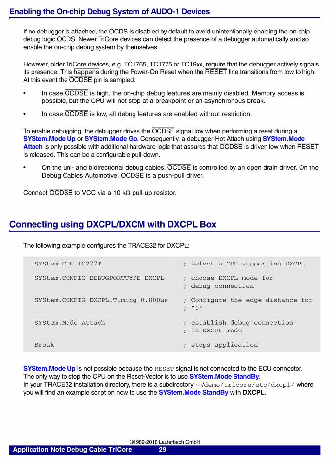
Connecting using DXCPL/DXCM with DXCPL Box
The following example configures the TRACE32 for DXCPL:
SYStem.Mode Up is not possible because the RESET signal is not connected to the ECU connector.The only way to stop the CPU on the Reset-Vector is to use SYStem.Mode StandBy.In your TRACE32 installation directory, there is a subdirectory ~~/demo/tricore/etc/dxcpl/ where you will find an example script on how to use the SYStem.Mode StandBy with DXCPL.
SYStem.CPU TC277T ; select a CPU supporting DXCPL
SYStem.CONFIG DEBUGPORTTYPE DXCPL ; choose DXCPL mode for; debug connection
SYStem.CONFIG DXCPL.Timing 0.800us ; Configure the edge distance for; “0”
SYStem.Mode Attach ; establish debug connection; in DXCPL mode
Break ; stops application
Application Note Debug Cable TriCore 29 ©1989-2018 Lauterbach GmbH

Debugging via the OCDS Debug Cable:
Debugging via the Automotive Debug Cable:
A TriBoard TC2x9 with TC299T C Bidirectional OCDS Debug Cable
B CAN port (CAN1) D DXCPL Box
A TriBoard TC2x9 with TC299T C Automotive Debug Cable
B CAN port (CAN1) D DXCPL Box
A
C
D
B
A
C
D
B
Application Note Debug Cable TriCore 30 ©1989-2018 Lauterbach GmbH

Sharing the Debug Port between TRACE32 and 3rd-Party Tool
Some tools like an ETAS ETK access the target using the JTAG or DAP debug port as well. It is possible to use such a tool and the debugger simultaneously. For details, see “Parallel Usage of a 3rd-Party Tool” (debugger_tricore.pdf).
For an ETK use an ETKF5 adapter to connect the debugger. For a correct auto-detection, the ETKF adapter version must be version ETKF5.1 or higher.
DAP User Pins
The DAP user pins USER0 and USER1 can be used independently either as input or output. Although their purpose is not defined by the specification, their availability is dependent on the following:
• USER0 and USER1 cannot be used in JTAG mode.
• USER0 cannot be used in DAP3 mode.
• USER1 can only be used when the target hardware ensures that the CPU is always in DAP mode.
• If a break pin (BRKIN, BRKOUT) is mapped to an unused JTAG pin, the corresponding pin of the debug connector cannot be used as a DAP user pin.
The DAP user pins can be configured by using the commands SYStem.CONFIG DAP.USER0 and SYStem.CONFIG DAP.USER1. If configured as input, the PRACTICE functions DAP.USER0() and DAP.USER1() can be used to read the status.
The following example configures the USER0 pin as output, sets the pin low and then high:
The following example configures the USER1 pin as input and prints the status:
A possible use case for the user pins could be disabling an external watchdog circuit, e.g. for FLASH programming or checking an important hardware status.
SYStem.CONFIG DAP.USER0 OUT ; USER0 pin is output
SYStem.CONFIG DAP.USER0 Set LOW ; USER0 pin is low
SYStem.CONFIG DAP.USER0 Set HIGH ; USER0 pin is high
SYStem.CONFIG DAP.USER1 IN ; USER1 pin is input
IF (DAP.USER1()==1)
PRINT "external event occurred" ; perform some action
Application Note Debug Cable TriCore 31 ©1989-2018 Lauterbach GmbH
Break Pins
Some TriCore devices have two internal Break Buses. Their state can be made visible by using the package’s break pins BRKIN and BRKOUT. The break pins are not required for debug operation. They can be connected to the debugger’s internal break bus, e.g. for triggering from or to external sources such as the PowerProbe or the PowerIntegrator, third-party tools such as logic analyzers or even other devices in a multi-core/ multi-chip scenario. In most cases it is safe to omit the break pins.
• On all debug cables BRKIN has a 47 serial resistor, BRKOUT has a 47 k pull-up resistor.
• BRKIN and BRKOUT are implemented as GPIO pins and may require manual configuration on the target.
• Whether a break pin is input or output for a break bus must be configured in MCBS (Multi Core Break Switch) via the TrOnchip commands. MCBS is also used to configure to or from which module the events on the break buses are routed.
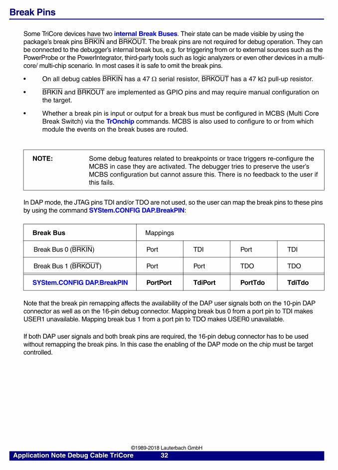
In DAP mode, the JTAG pins TDI and/or TDO are not used, so the user can map the break pins to these pins by using the command SYStem.CONFIG DAP.BreakPIN:
Note that the break pin remapping affects the availability of the DAP user signals both on the 10-pin DAP connector as well as on the 16-pin debug connector. Mapping break bus 0 from a port pin to TDI makes USER1 unavailable. Mapping break bus 1 from a port pin to TDO makes USER0 unavailable.
If both DAP user signals and both break pins are required, the 16-pin debug connector has to be used without remapping the break pins. In this case the enabling of the DAP mode on the chip must be target controlled.
NOTE: Some debug features related to breakpoints or trace triggers re-configure the MCBS in case they are activated. The debugger tries to preserve the user’s MCBS configuration but cannot assure this. There is no feedback to the user if this fails.
Break Bus Mappings
Break Bus 0 (BRKIN) Port TDI Port TDI
Break Bus 1 (BRKOUT) Port Port TDO TDO
SYStem.CONFIG DAP.BreakPIN PortPort TdiPort PortTdo TdiTdo
Application Note Debug Cable TriCore 32 ©1989-2018 Lauterbach GmbH
Controlling an External Watchdog
Depending on the used debug cable, an external watchdog can either be controlled using the OCDSE or the WDTDIS signal:
• The OCDSE signal can be driven low by the debugger. This is controlled by SYStem.Option OCDSELOW.
• The WDTDIS signal can be driven low and high by the debugger. This is controlled by SYStem.CONFIG EXTWDTDIS.
Application Note Debug Cable TriCore 33 ©1989-2018 Lauterbach GmbH

Adapters, Converters and Extensions
An adapter or converter is necessary to connect a debug cable and/or a trace preprocessor to a target board in case different connector types are used or the pin assignment is different.
• An adapter just adapts from one connector type to another, the signal mapping and pin numbers are identical. An example is the half-size adapter which allows to connect a debug cable with a standard 2.54 inch (100 mil) plug to a target using a standard 1.27 inch (50 mil) connector.
An adapter is always passive so no power supply is required.
The term adapter is today mainly used with emulator-related products, for example adapters for ICE and FIRE.
• A converter allows connecting devices with different signal mappings and connector types. An example is the converter for the 26-pin automotive debug cable to a target using a 16-pin OCDS JTAG connector. Unused signals are connected to GND, VCC or are not connected at all. There may also be a jumper or soldering option for a user-specific solution.
Converters can connect two or more devices with each other, e.g. they connect a debug cable and a trace preprocessor to the target board using a single target connector.
Converters may be passive or active. An active converter needs an additional power supply, e.g. for signal level adaption or glue logic. Most active converters get this additional power from the target (VCC, VCCS or VTREF).
Almost all converters are related to debuggers and trace preprocessors.
Adapter 16-pin 100 mil to 50 mil
The 16-pin half-size adapter can be used to connect a 100 mil 16-pin plug to a 50 mil connector, e.g. for using a small-size 16-pin debug connector. The signals are mapped 1:1, so this is a general purpose adapter.
Recommended target connector: Half-size 2x8 connector.
Order-Code Description
LA-2102 Adapter 16-pin 100 mil to 50 mil
Application Note Debug Cable TriCore 34 ©1989-2018 Lauterbach GmbH

Converter 16-pin JTAG to DAP for TriCore/XC2000/XC800
The DAP converter is required for converting the DAP signals of the 16-pin OCDS bidirectional debug cable to the 10-pin Infineon DAP connector. This converter is mandatory when using DAP with the XC2000, XC800 or XE16x chip family, it is optional for the TriCore family.
Recommended target connector: Half-size 2x5 connector with keying pin 7.
For pin assignment, please see chapter “DAP Connector”, page 11.
Order-Code Description
LA-3815 Converter 16-pin JTAG to DAP for TriCore/XC2000/XC800
Application Note Debug Cable TriCore 35 ©1989-2018 Lauterbach GmbH

Converter DXCPL Box for TriCore
The DXCPL-Box converts between the logical level of the TXD/RXD pins of the 16-pin OCDS bidirectional debug cable or the 26-pin Automotive Debug Cable and the electrical signaling of the CAN bus (CANL/CANH).
Block Diagram:
A PODBUS connector C Connector for the Automotive Debug Cable
B Connector for the OCDS Debug Cable D CAN D-Sub connector
Order-Code Description
LA-3888 DXCPL Box (DAP over CAN Physical Layer)
C
D
B
A
Application Note Debug Cable TriCore 36 ©1989-2018 Lauterbach GmbH

Converter 16-pin JTAG to BOSCH MEDC17 for TriCore
The converter is required for converting the JTAG signals of the 16-pin OCDS debug cable to the 10-pin BOSCH MEDC17 connector used on BOSCH targets.
Recommended target connector: Half-size 2x5 connector.
Converter AUTO26/ OnCE14-PPC/ JTAG16-TC to ECU14
The converter is required for connecting the 26-pin Debug Cable Automotive-, the 16-pin OCDS TriCore- or the 14-pin OnCE PowerPC debug cable to the 10-pin half-size ECU14 connector used on BOSCH and Continental targets.
Pin 7 (USERIO) can be configured as break- or event input/output (TriCore or PowerPC), OCDSE (TriCore only) or can permanently be connected to GND or VCC (TriCore or PowerPC), e.g. for enabling or disabling an external watchdog.
The target adapter PCB can be ordered as replacement part. There is also a robust version using a through hole connector instead of an SMD connector.
Additional information: http://www.lauterbach.com/ad3843.html
Order-Code Description
LA-3819 Converter 16-pin JTAG to BOSCH MEDC17 for TriCore
A B
Application Note Debug Cable TriCore 37 ©1989-2018 Lauterbach GmbH

Recommended target connector: TFM 2x5 connector.
Converter AUTO26 to ECU14
The converter is a small version of the above converter. It is required for connecting the 26-pin Automotive Debug Cable to the 10-pin half-size ECU14 connector used on BOSCH and Continental targets.
Pin 7 (USERIO) can be configured as break- or event input/output (TriCore or PowerPC), OCDSE (TriCore only) or can permanently be connected to GND or VCC (TriCore or PowerPC), e.g. for enabling or disabling an external watchdog.
The target adapter PCB can be ordered as replacement part. There is also a robust version using a through-hole connector instead of an SMD connector.
Additional information: http://www.lauterbach.com/ad2745.html
Recommended target connector: TFM 2x5 connector.
Order-Code Description
LA-3843 Conv. AUTO26/ OnCE14-PPC/ JTAG16-TC to ECU14
LA-2743 (Replacement) Target-Adapter-PCB from LA-3843 and LA-2745. See [A] above.
LA-2744 (Replacement) Target-Adapter-PCB from LA-3843 and LA-2745robust version with through-hole target connector. See [B] above.
Order-Code Description
LA-2745 Conv. AUTO26 to ECU14
LA-2743 (Replacement) Target-Adapter-PCB from LA-3843 and LA-2745.
LA-2744 (Replacement) Target-Adapter-PCB from LA-3843 and LA-2745robust version with through-hole target connector.
Application Note Debug Cable TriCore 38 ©1989-2018 Lauterbach GmbH
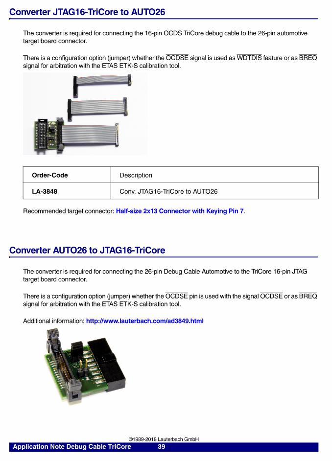
Converter JTAG16-TriCore to AUTO26
The converter is required for connecting the 16-pin OCDS TriCore debug cable to the 26-pin automotive target board connector.
There is a configuration option (jumper) whether the OCDSE signal is used as WDTDIS feature or as BREQ signal for arbitration with the ETAS ETK-S calibration tool.
Recommended target connector: Half-size 2x13 Connector with Keying Pin 7.
Converter AUTO26 to JTAG16-TriCore
The converter is required for connecting the 26-pin Debug Cable Automotive to the TriCore 16-pin JTAG target board connector.
There is a configuration option (jumper) whether the OCDSE pin is used with the signal OCDSE or as BREQ signal for arbitration with the ETAS ETK-S calibration tool.
Additional information: http://www.lauterbach.com/ad3849.html
Order-Code Description
LA-3848 Conv. JTAG16-TriCore to AUTO26
Application Note Debug Cable TriCore 39 ©1989-2018 Lauterbach GmbH

Recommended target connector: Standard 2x8 Connector.
Converter Samtec 60 to AMP 40
This converter is used to connect a TriCore preprocessor with a Samtec 60-pin plug to a target board with an AMP 40-pin OCLDS-L2 connector. The converter is also available in the other direction AMP 40-pin to Samtec 60-pin, ask for it.
Please note that AMP 40-pin OCDS-L2 connector does not define debug signals.
Recommended target connector: AMP 40 Connector.
Converter 16-pin OCDS-L1 to Samtec 60 for TriCore
Many TriCore targets use the Samtec 60-pin OCDS-L2 trace connector. This interface also defines the JTAG signals. The OCDS-L2 preprocessor for TriCore LA-7928 has a connector for the 16-pin JTAG plug. In case no preprocessor is connected, this adapter can be used for connecting the OCDS debug cable to the Samtec 60-pin connector, thus eliminating the need for an extra 16-pin debug connector.
The signal description of the Samtec 60-pin connector is not part of this application note. For details see:
• Chapter Samtec 60 Connector in “TriCore Debugger and Trace” (debugger_tricore.pdf).
• http://www.lauterbach.com/ad7941.html
• http://www.lauterbach.com/adocds2.html
Order-Code Description
LA-3849 Conv. AUTO26 to JTAG16-TriCore
Order-Code Description
LA-7927 Conv. Samtec 60 to AMP 40
Application Note Debug Cable TriCore 40 ©1989-2018 Lauterbach GmbH

Recommended target connector: Samtec 60 connector.
Converter 16-pin OCDS-L1/ 40-pin HSSTP to ERF8 for TriCore
Many TriCore target boards support a 22-pin ERF8 serial trace connector. This interface also defines the debug signals (JTAG, DAP). This converter is required for connecting the serial trace preprocessor LA-3912 and the 16-pin TriCore debug cable LA-7756 or the Debug Cable Automotive to the ERF8 connector.
Pin 18 (TRIG) can be configured to be OCDSE or BRKOUT (soldering option only).
The signal description of the 22-pin ERF8 connector is not part of this application note. For details see:
• http://www.lauterbach.com/ad3829.html
Recommended target connector: ERF8 22-pin Power.org connector.
Order-Code Description
LA-7941 Converter 16-pin OCDS-L1 to Samtec 60 for TriCore
Order-Code Description
LA-3829 Conv. Samtec40 to Samtec22 TriCore AGBT
Application Note Debug Cable TriCore 41 ©1989-2018 Lauterbach GmbH

Converter OCDS-L1/ AUTO26/ PowerTrace Serial to ERF8 for TriCore
Many TriCore target boards support a 22-pin ERF8 serial trace connector. This interface also defines the debug signals (JTAG, DAP). This converter is required for connecting the PowerTrace Serial LA-3555 and the 16-pin TriCore debug cable LA-7756 or an Automotive Debug Cable to the ERF8 connector.
Pin 18 (TRIG) can be configured to be OCDSE or BRKOUT (soldering option only).
The signal description of the 22-pin ERF8 connector is not part of this application note. For details see:
• http://www.lauterbach.com/ad3556.html
Recommended target connector: ERF8 22-pin Power.org connector.
Flex Extension for SAMTEC 60-pin QTH-QSH series
This cable is an extension for connecting a TriCore OCDS-L2 preprocessor with a 60-pin Samtec connector to a target board. The use of this cable is highly recommended to avoid a mechanical damage to the connectors.
Order-Code Description
LA-3556 AGBT Trace Adapter for PowerTrace Serial
Application Note Debug Cable TriCore 42 ©1989-2018 Lauterbach GmbH
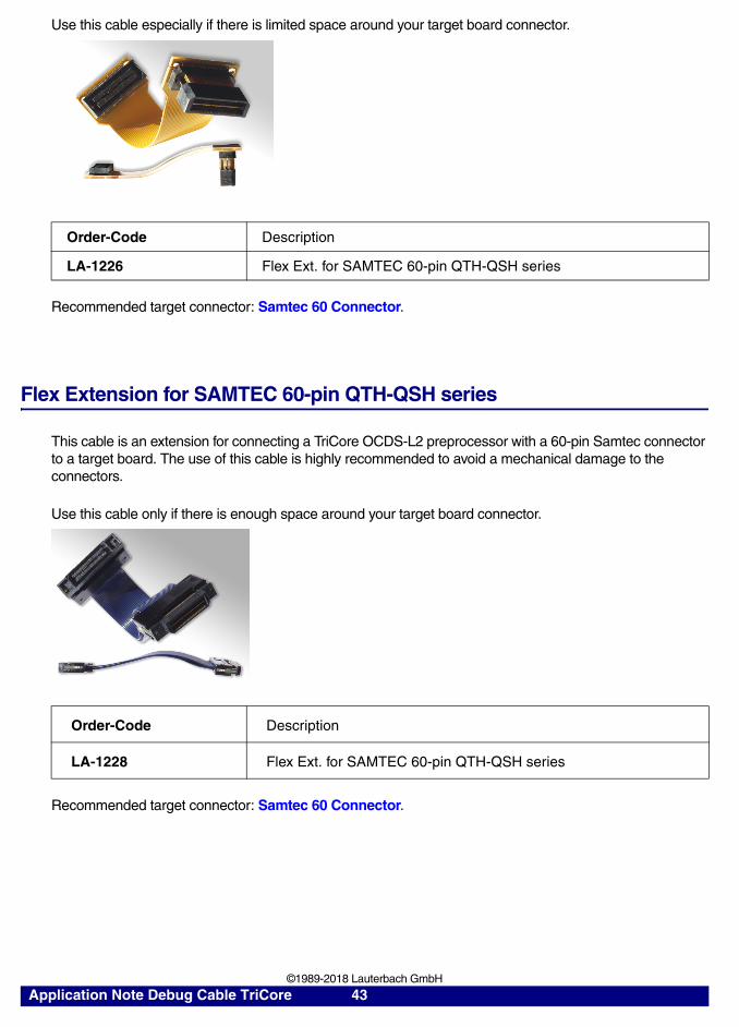
Use this cable especially if there is limited space around your target board connector.
Recommended target connector: Samtec 60 Connector.
Flex Extension for SAMTEC 60-pin QTH-QSH series
This cable is an extension for connecting a TriCore OCDS-L2 preprocessor with a 60-pin Samtec connector to a target board. The use of this cable is highly recommended to avoid a mechanical damage to the connectors.
Use this cable only if there is enough space around your target board connector.
Recommended target connector: Samtec 60 Connector.
Order-Code Description
LA-1226 Flex Ext. for SAMTEC 60-pin QTH-QSH series
Order-Code Description
LA-1228 Flex Ext. for SAMTEC 60-pin QTH-QSH series
Application Note Debug Cable TriCore 43 ©1989-2018 Lauterbach GmbH

Cable 26-pin for Automotive Debug Cables
This cable is required for connecting the 26-pin Debug Cable Automotive to a 26-pin automotive target debug connector. This is a replacement part for all Automotive Debug Cables.
Recommended target connector: Half-size 2x13 connector with keying pin 7.
Cable 20-pin for Automotive Debug Cables
This cable is required for connecting the 26-pin Debug Cable Automotive to a 20-pin automotive target debug connector. This is a replacement part for all Automotive Debug Cables.
The cable does not support the signals 21 to 26, which are only required for arbitration with a third-party tool.
Recommended target connector: Half-size 2x10 connector with keying pin 7.
Order-Code Description
LA-1949 Automotive-HALF-SIZE-CABLE 26-26
Order-Code Description
LA-1948 Automotive-HALF-SIZE-CABLE 26-20
Application Note Debug Cable TriCore 44 ©1989-2018 Lauterbach GmbH

Cable 10-pin for Automotive Debug Cables
This cable is required for connecting the 26-pin Debug Cable Automotive to a 10-pin automotive target debug connector. This is a replacement part for all Automotive Debug Cables.
The cable does not support the signals 11 to 26. The remaining pins are the absolute minimum required for a JTAG debug connection. DAP is supported as well, the pinout is the same as specified by Infineon.
Recommended target connector: Half-size 2x5 connector with keying pin 7.
Order-Code Description
LA-1947 Automotive-HALF-SIZE-CABLE 26-10
Application Note Debug Cable TriCore 45 ©1989-2018 Lauterbach GmbH

Recommended Connectors
Lauterbach recommends using connectors with shroud for assuring correct polarization. Otherwise the target and/or the debugger might get damaged.
Do not extend the Debug Cable to avoid bad signal quality, e.g. by increased EMC influences.
Standard 2x8 Connector
• Standard 16 pin double row connector (two rows of 8 pins)
• Pin to pin spacing: 100 mil = 0.1 inch = 2.54 mm
• Connector example:
Half-size 2x8 Connector
• Half-size 16 pin double row connector (two rows of 8 pins)
• Pin to pin spacing: 50 mil = 0.05 inch = 1.27 mm
Seltronics HC 2532-016-SW If a terminal strip without shroud is used, the spacing marked with "A" must be a minimum of 25.5mm/1" (see picture).
Application Note Debug Cable TriCore 46 ©1989-2018 Lauterbach GmbH
• Connector examples:
Half-size 2x5 Connector
• Half-size 10 pin double row connector (two rows of 5 pins)
• Pin to pin spacing: 50 mil = 0.05 inch = 1.27 mm
• Connector examples:
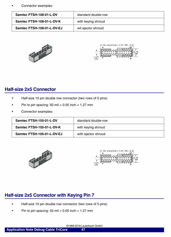
Half-size 2x5 Connector with Keying Pin 7
• Half-size 10 pin double row connector (two rows of 5 pins)
• Pin to pin spacing: 50 mil = 0.05 inch = 1.27 mm
Samtec FTSH-108-01-L-DV standard double-row
Samtec FTSH-108-01-L-DV-K with keying shroud
Samtec FTSH-108-01-L-DV-EJ wit ejector shroud
Samtec FTSH-105-01-L-DV standard double-row
Samtec FTSH-105-01-L-DV-K with keying shroud
Samtec FTSH-105-01-L-DV-EJ with ejector shroud
Application Note Debug Cable TriCore 47 ©1989-2018 Lauterbach GmbH

• Connector examples:
The picture below shows the version without keying pin.
Half-size 2x10 Connector with Keying Pin 7
• Half-size 20 pin double row connector (two rows of 10 pins)
• Pin to pin spacing: 50 mil = 0.05 inch = 1.27 mm
• Pin 7 is removed (keying pin for polarization)
• Connector examples:
Samtec FTSH-105-01-L-DV standard double-row, remove pin 7 manually
Samtec FTSH-105-01-L-DV-K with keying shroud, remove pin 7 manually
Samtec ASP-168330-03 This is an Application Specific Product code for FTSH-105-01-L-DV--K--P-TR-POL (keying shroud, pick & place pad, tape & reel) with pin 7 already removed. When ordering this version from Samtec, please refer to Lauterbach.
Samtec FTSH-105-01-L-DV-EJ with ejector shroud, remove pin 7 manually
Samtec FTSH-110-01-L-DV standard double-row, remove pin 7 manually
Samtec FTSH-110-01-L-DV-K with keying shroud, remove pin 7 manually
Samtec ASP-168330-02 This is an Application Specific Product code for FTSH-110-01-L-DV--K--P-TR-POL (keying shroud, pick & place pad, tape & reel) with pin 7 already removed. When ordering this version from Samtec, please refer to Lauterbach.
Samtec FTSH-110-01-L-DV-EJ with ejector shroud, remove pin 7 manually
Application Note Debug Cable TriCore 48 ©1989-2018 Lauterbach GmbH

The picture below shows the version without keying pin.
Half-size 2x13 Connector with Keying Pin 7
• Half-size 26 pin double row connector (two rows of 13 pins)
• Pin to pin spacing: 50 mil = 0.05 inch = 1.27 mm
• Pin 7 is removed (keying pin for polarization)
• Connector examples:
The picture below shows the version without keying pin.
Samtec FTSH-113-01-L-DV standard double-row, remove pin 7 manually
Samtec FTSH-113-01-L-DV-K with keying shroud, remove pin 7 manually
Samtec ASP-168330-01 This is an Application Specific Product code for FTSH-113-01-L-DV--K--P-TR-POL (keying shroud, pick & place pad, tape & reel) with pin 7 already removed. When ordering this version from Samtec, please refer to Lauterbach.
Samtec FTSH-113-01-L-DV-EJ with ejector shroud, remove pin 7 manually
Application Note Debug Cable TriCore 49 ©1989-2018 Lauterbach GmbH
TFM 2x5 Connector
• 10 pin double row connector (two rows of 5 pins) with surrounding shroud
• Pin to pin spacing: 50 mil = 0.05 inch = 1.27 mm
• Mechanical polarization at pin 10
• Connector examples:
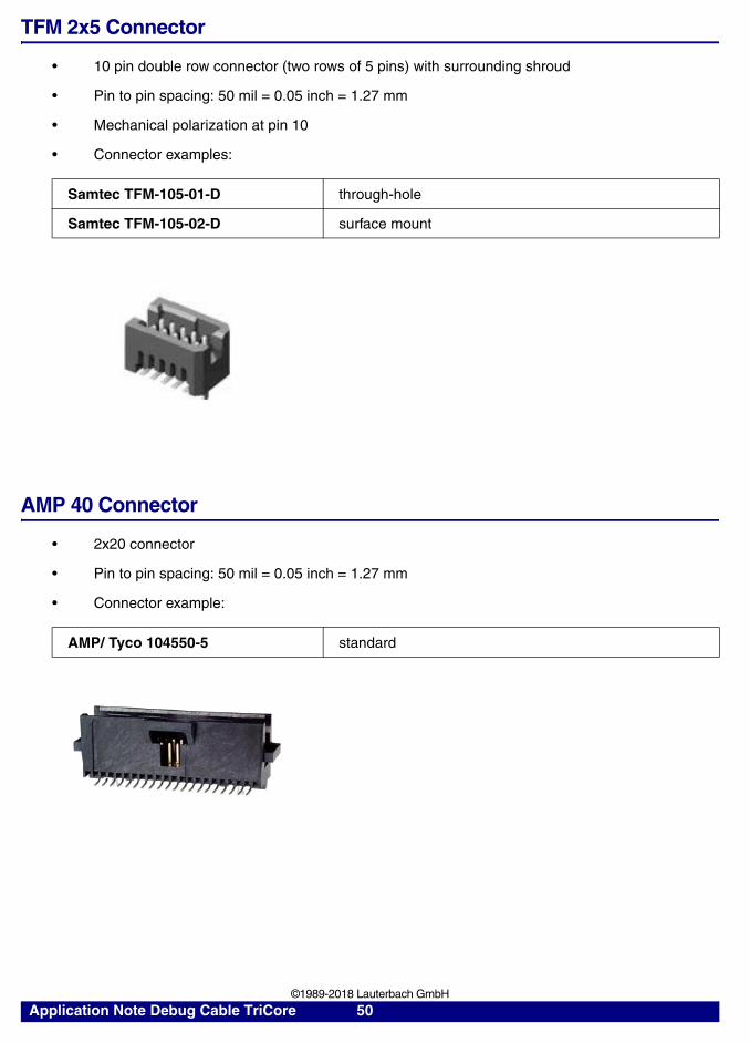
AMP 40 Connector
• 2x20 connector
• Pin to pin spacing: 50 mil = 0.05 inch = 1.27 mm
• Connector example:
Samtec TFM-105-01-D through-hole
Samtec TFM-105-02-D surface mount
AMP/ Tyco 104550-5 standard
Application Note Debug Cable TriCore 50 ©1989-2018 Lauterbach GmbH
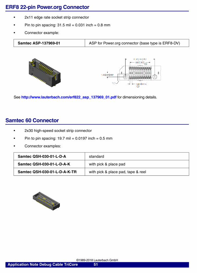
ERF8 22-pin Power.org Connector
• 2x11 edge rate socket strip connector
• Pin to pin spacing: 31.5 mil = 0.031 inch = 0.8 mm
• Connector example:
See http://www.lauterbach.com/erf822_asp_137969_01.pdf for dimensioning details.
Samtec 60 Connector
• 2x30 high-speed socket strip connector
• Pin to pin spacing: 19.7 mil = 0.0197 inch = 0.5 mm
• Connector examples:
Samtec ASP-137969-01 ASP for Power.org connector (base type is ERF8-DV)
Samtec QSH-030-01-L-D-A standard
Samtec QSH-030-01-L-D-A-K with pick & place pad
Samtec QSH-030-01-L-D-A-K-TR with pick & place pad, tape & reel
Application Note Debug Cable TriCore 51 ©1989-2018 Lauterbach GmbH