IRC5-IRB2400 Prod Man Part2 3HAC022031-001_revA_en_references
IntroductionThe purpose of this document is to guide the reader through the process of establishing communication between an existing ABB IRC5 robotic controller and an ABB CP600 HMI panel. Working knowledge of ABB Robot studio and Automation Builder software is assumed.
Using cross connections to control certain system functions (e.g motors on, motors off) from the HMI panel will also be covered.
Requirements − ABB Robot / IRC5 Controller − CP600 HMI Panel − PC with Automation Builder V1.1 or later with *Robot Stu-
dio installed. − Ancillary equipment: 10/100 Ethernet switch, Ethernet
cables
*A separate license must be purchased to use Robot Studio off-line. However, it is not required and this procedure applies to on-line or off-line programming
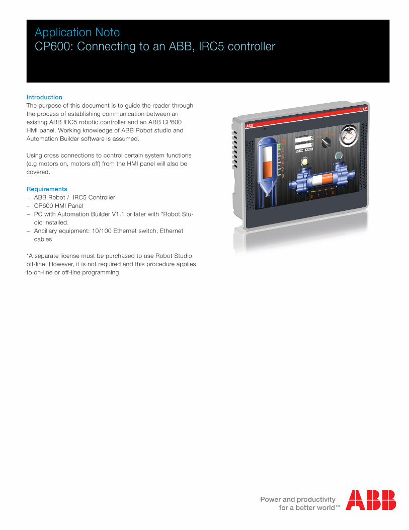
Application NoteCP600: Connecting to an ABB, IRC5 controller
Configure the IRC5 Robotic Controller1. Connect the PC with Robot Studio to one of the Ethernet ports on the CP600 panel. Connect the IRC5 LAN Ethernet to the
other.
2. Open existing, or create new Robot Studio Project. The Robot Studio and Panel Builder projects may be created discretely, or they may be contained within a single Automation Builder project.
3. Open Robot studio and navigate to the controller tab.
4. Click on the “Add Controller” icon, then select “Add Controller”.
5. Select the robot you wish to work with and click “OK”. The robot information will appear in the project tree.
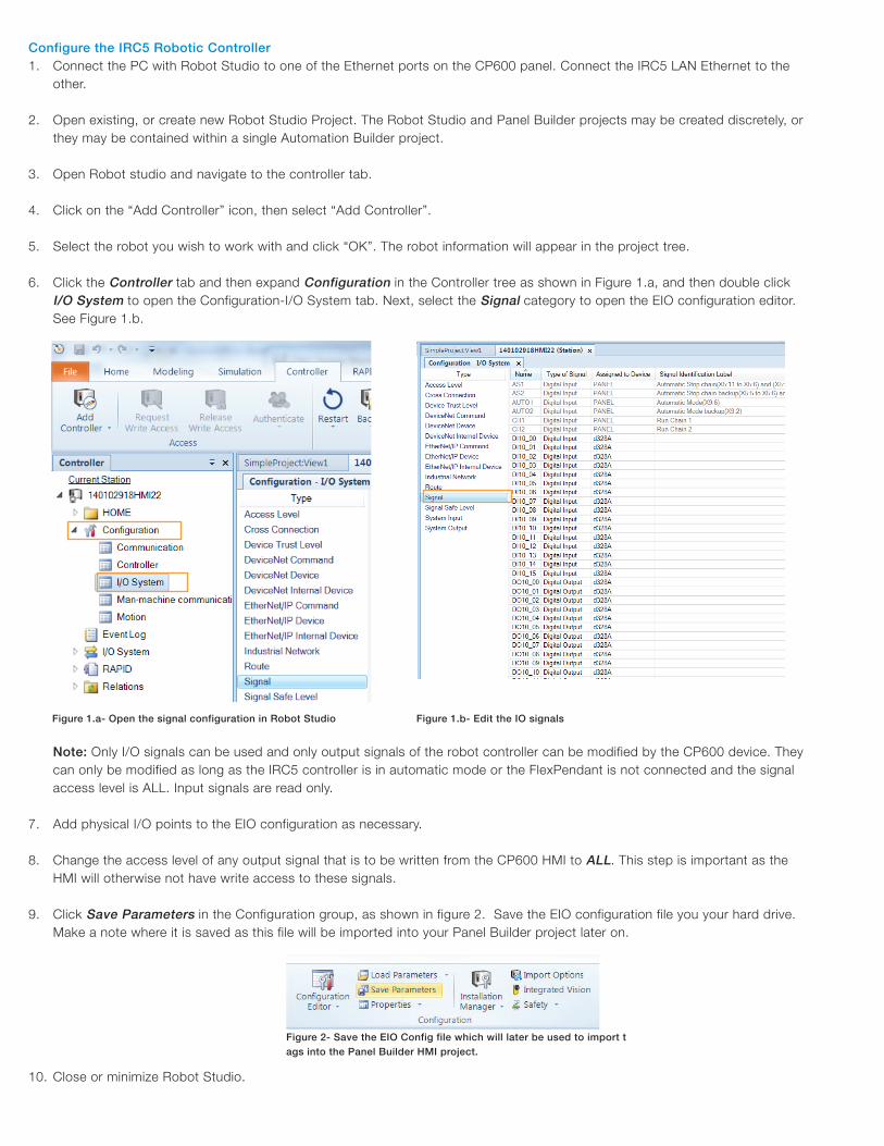
6. Click the Controller tab and then expand Configuration in the Controller tree as shown in Figure 1.a, and then double click I/O System to open the Configuration-I/O System tab. Next, select the Signal category to open the EIO configuration editor. See Figure 1.b.
Note: Only I/O signals can be used and only output signals of the robot controller can be modified by the CP600 device. They can only be modified as long as the IRC5 controller is in automatic mode or the FlexPendant is not connected and the signal access level is ALL. Input signals are read only.
7. Add physical I/O points to the EIO configuration as necessary.
8. Change the access level of any output signal that is to be written from the CP600 HMI to ALL. This step is important as the HMI will otherwise not have write access to these signals.
9. Click Save Parameters in the Configuration group, as shown in figure 2. Save the EIO configuration file you your hard drive. Make a note where it is saved as this file will be imported into your Panel Builder project later on.
10. Close or minimize Robot Studio.
Figure 1.a- Open the signal configuration in Robot Studio Figure 1.b- Edit the IO signals
Figure 2- Save the EIO Config file which will later be used to import tags into the Panel Builder HMI project.

Creating the HMI Project in Panel Builder1. If using Panel Builder 600 stand-alone software package to create your HMI then create a new project and proceed to step
4.3. Otherwise, from within Automation Builder create a new CP600 project by right-clicking project name at the top of the Devices tree and adding a new CP600 or CP600-eCo object as shown in Figure 3.
Figure 3- Creating a new Panel Builder project within Automation Builder.
2. Double-click the newly created Panel Project in the Devices tree to open Panel Builder 600. When prompted, select new project and click OK.
3. When panel builder opens your project for the first time the Project Wizard dialog appears. Select the panel type and display orientation, then click OK ( see Figure 4).
Figure 4- Configure the Panel Builder project
4. Open the Protocols tab by double-clicking the Protocol icon in the ProjectView tree.
5. Click the add protocol , + icon at the top left of the Protocol tab, and then select the ABB IRC5 protocol from the PLC drop-down list (see Figure 5). The protocol editor dialog will open.
Figure 5- Add and configure the ABB IRC5 communication protocol.

6. The only mandatory setting in the protocol editor is the IP address. Enter the IP address of the IRC5 in this field. If desired, enter an arbitrary alias to identify the IRC5 controller in your project.
Check the PLC box only if the panel will connect to more than one IRC5 controller, then enter the IP address for each controller.7. Next, open the Tags tab by double-clicking the Tags icon in the ProjectView tree.
8. Ensure the IRC5 protocol is selected in the dropdown at the top of the Tags tab, then click the import tags button, >] ,as illus-trated in figure 6. When prompted select the CFG_1.0:5:0: importer and click OK.
Figure 6- Import the EIO config file, which Panel Builder will use to create tags for the IRC5 protocol.
9. Navigate to the EIO config file saved in step 3.9, and then click Open. All of the available tags from the IRC5 controller will ap-pear in a list at the bottom of the Tags tab. Select one or more tags to import into your project and click the Import Tags button (Figure 7).
Panel builder supports the following tag (signal) types: − Bool (DI, DO) − UINT (GI, GO) − Real (GI, GO, AI, AO)
Hint: Use shift-click or Ctrl-click key combinations to select multiple tags.
Figure 7- Import tags from the EIO Config file.

10. Now the HMI pages can be created. Start by clicking the empty page in the ProjectView tree. By default this page will be the first page that appears when the CP600 boots up. More pages can be created by right-clicking the Page folder and selecting Insert New Page from the context menu.
11. As shown in Figures 8.a and 8.b, various elements, or widgets can be dragged from the Widget Gallery and dropped onto your project. Attach IRC5 tags to the widgets simply by clicking the add tag [+] icon in the Value property for the currently highlighted widget and selecting the tag from the tag list.
Hint: click on a palate heading in the Widget Gallery to bring up more widget options (see Figure 10).
Figure 8.a- Drag control elements, or widgets onto the HMI screen.
12. You can edit other properties for each widget such as text, size, color etc… Anywhere the + icon appears you can attach a tag to change that property dynamically during run time.
13. Save your project by clicking the Save Project icon .
14. Before loading the HMI project to the panel, the panel IP address must be configured to communicate on the same subnet as the IRC5 controller. Choose a unique network address that exists on the same subnet. That is to say if the IRC5 IP address is AAAA.BBBB.CCCC.DDDD the panel address must be set to AAAA.BBBB.CCCC.EEEE where EEEE is a value between 0000 and 0254 and is a unique ID on the network.
Note: The IP address of the IRC 5 controller can be viewed on the Flex Pendant − Apply power to the panel and allow it to boot-up. − If the panel boots to a black screen with two icons in the upper left corner then select System Settings to open the
system menu (if this is the case the panel does not yet have a runtime system installed. Configure the IP address as instructed below and then refer to appendix A for instructions on installing the runtime system). If the panel boots to anything other than described above press a spot on the screen for several seconds until the contextual menu appears and select Show System Settings…
− Press Next or Back until Network is highlighted. Change the IP address of the panel and ensure the Subnet Mask is set to 255.255.255.0. Close the Network settings dialog and reboot the panel. Hint: the touchscreen is resistive so a pen cap or other stylus can be used to type values into the IP value field.
15. Now the project can be loaded to the panel by selecting Download to Target from the Run menu. When the Download to Target dialog opens simply enter the IP address of the CP600 panel (or click [V] to find the panel on the network) and click Download.
16. Test your HMI project.

Creating Cross Connections
1. To create a cross connection open your project in Robot Studio.2. Click the Controller tab and then expand Configuration in the Controller tree as shown in Figure 1.a, and then double click I/O
System to open the Configuration-I/O System tab. Next, select the Signal category.3. Create the desired signals to be cross connected to controller output signals. Remember to set the Access Level to ALL.4. Now select the Cross Connection category.5. Right-click the Cross Connection category and select New Cross Connection from the context menu.6. Enter settings for the cross connection as follows:
Setting Value
Name Unique but arbitrary tag name
Resultant Destination signal (i.e. output) for the cross connection
Actor This is the signal that will be cross connect, or copied to the Resultant signal
Invert Optional, if Yes is selected the Resultant signal will be the reciprocal of the Actor signal
Operator Optional, logical operation if the Resultant signal is to be the logical AND or OR of multiple Actors.
Actor2…5 Actors that will be ANDed or Ored with the Actor if an operator is selected
7. Select Save Parameters from the Configuration group once all of the desired cross connections have been created.8. Refer to steps 7-9 in Creating the HMI Project in Panel Builder section to import cross connection signals to the Panel Builder
HMI project.

Appendix A – Installing the CP600 Runtime System
HMI devices are delivered from factory without Runtime.When you power up the device for the first time, the Runtime Loader window is displayed.
The Runtime Loader presence depends on the device Operating System and may not be available on all the units.
Installing Runtime with a project
1. Click System settings: the System menu is activated in user mode.
2. Download a project with PB610 Panel Builder 600 to install the Runtime. When you download a project the Runtime is automatically installed if needed. See “Transferring the project to HMI device” for details.
3. Click Install Runtime: the procedure is run automatically.

Installing Runtime from a USB drive
Important: Old versions of HMI devices may not include the Runtime Loader. Contact technicalsupport if you need further information.
1. Prepare the Update Package by selecting Run > Manage Target. Next click Update Package.
2. Plug the USB drive in the device and click Transfer from disk.
3. Follow the instructions displayed.

Reference Document
Document Name Document Number Rev/Ver
Panel Builder programming software manual for CP600 control panels 3ADR059001M0207_PB610_Panel_Builder_600_EN.pdf Rev 2.00
Panel Builder programming software manual for CP600-eCo control panels 3ADR059056M0201_PB610-B_Panel_Builder_600_EN.pdf Rev 2.00
Communication protocols for CP600 control panels 3ADR059053M0201.pdf V1.91
Robot Studio programming manual 3HAC032104-001 Rev 6.01