Feature-based Image Comparison and Its Application in Wireless

MPC89L516(556)X2
Application Note
This document contains information on a new product under development by MEGAWIN. MEGAWIN reserves the right to change or discontinue this product without notice. MEGAWIN Technology Co., Ltd. 2003 All rights reserved. 2005/02 version A2.3
MEGAWIN
Contents
0. Features
1. Pin Assignment 2. Special Function Registers
3. Extended and 5V-tolerant GPIO Ports New Feature
4. On-chip eXpanded RAM (XRAM) New Feature 5. Second DPTR New Feature
6. Up/Down Counting of Timer 2 New Feature
7. Programmable Clock-Out New Feature 8. Enhanced UART New Feature
9. Seven Interrupt Sources and Four-Priority-Level Nested Structure New Feature
10. Wake-up from Power-down by External Interrupt New Feature 11. Watchdog Timer (WDT) New Feature
12. Reduced EMI Mode New Feature
13. 12T Mode and 6T Mode New Feature 14. In-System-Programming (ISP) New Feature
15. Non-volatile Data Application using ISP New Feature
16. Power-ON Flag New Feature 17. Analog-to-Digital Converter (Only for MPC89L556X2) New Feature
18. Option Registers
19. Flash Memory Configuration 20. XTAL Oscillating Requirement and ALE Output Frequency
21. Power Consumption
22. Notes on Using External Interrupt 23. How to Reduce EMI
24. UART Baudrate Setting

2 MPC89L516(556)X2 Technical Summary MEGAWIN
Revision History
Version Revision
1.0 The first-time released.
2.0 Re-write ver 1.0
2.1
(1) Modify Section 0 to “Features”. (2) Add more description for in Section 12. (3) Add short introduction to ISP in Section 14. (4) Re-arrange the sequence from Section 16 to Section 23. (5) Add a new section, Section 21, “Power Consumption”. (6) Add a new section, Section 23, “How to reduce EMI”.
2.2
(1) Update operation speed in Section 0. (2) Modify the contents in Section 13. (3) Refine Section 14, and add new Section 14-7. (4) Update the attached file for “ISP technical support” in Section 14. (5) Modify PIN_EN description in Section 18. (6) Add Section 20-2. (7) Add a new section, Section 24, “UART Baudrate Setting”.
2.3 (1) Add “ISP Mode Select Table” and remove attached “ISP Technical Support” in Section 14. (2) Modify notes on using the external interrupts, Section 22.

MEGAWIN MPC89L516(556)X2 Technical Summary 3
0. Features • Compatible with Standard 8051 MCU • Flash Program Memory with In-System-Programming (ISP) Capability • Including All the 8052 Features, and New Powerful Features Are Added:
- Extended and 5V-tolerant GPIO Ports
- On-chip eXpanded RAM (XRAM)
- Second DPTR
- Up/Down Counting of Timer 2
- Programmable Clock-Out
- Enhanced UART
- Seven Interrupt Sources
- Four-Priority-Level Nested Interrupt Structure
- Wake-up from Power-down by External Interrupt
- Watchdog Timer (WDT)
- Reduced EMI Mode
- Non-volatile Data Application using ISP
- Power-ON Flag
- Analog-to-Digital Converter • 12T-mode and 6T-mode Operation • Operation Speed: up to 45 MHz for both 12T-mode and 6T-mode • Security Bits (LOCK, SB and MOVCL) • Endurance: 10,000 Write/Erase Cycles • Packages: 40-pin DIP, 44-pin PLCC and 44-pin QFP

4 MPC89L516(556)X2 Technical Summary MEGAWIN
1. Pin Assignment
MPC89L516X2
1234567891011121314151617181920
4039383736353433323130292827262524232221
40-pinDIP
VDDP0.0/AD0P0.1/AD1P0.2/AD2P0.3/AD3P0.4/AD4P0.5/AD5P0.6/AD6P0.7/AD7-EAALE-PSENP2.7/A15P2.6/A14P2.5/A13P2.4/A12P2.3/A11P2.2/A10P2.1/A9P2.0/A8
T2/P1.0T2EX/P1.1
P1.2P1.3P1.4P1.5P1.6P1.7RST
RXD/P3.0TXD/P3.1
-INT0/P3.2-INT1/P3.3
T0/P3.4T1/P3.5
-WR/P3.6-RD/P3.7
XTAL2XTAL1
VSS
891011121314151617 18 19 20 21 22 23 24 25 26 27 28
P4.0
-WR
/P3.
6-R
D/P
3.7
XTA
L2XT
AL1
VSS
A8/
P2.0
A9/
P2.1
A10
/P2.
2A
11/P
2.3
A12
/P2.
4
2930313233343536373839
P2.5/A13P2.6/A14P2.7/A15- PSENALEP4.1- EAP0.7/AD7P0.6/AD6P0.5/AD5P0.4/AD47
P1.6P1.7RST
RXD/P3.0P4.3
TXD/P3.1- INT0/P3.2- INT1/P3.3
T0/P3.4T1/P3.5
P1.5 44 43 42 41 40
P1.4
P1.3
P1.2
P1.1
/T2E
XP1
.0/T
2P4
.2VD
DP0
.0/A
D0
P0.1
/AD
1P0
.2/A
D2
P0.3
/AD
3
1 6 5 4 3 2
MPC89L516X2P MPC89L516X2F
44-pin PLCC
234567891011 12 13 14 15 16 17 18 19 20 21 22 23
24252627282930313233
P2.5/A13P2.6/A14P2.7/A15- PSENALEP4.1- EAP0.7/AD7P0.6/AD6P0.5/AD5P0.4/AD41
P1.6P1.7RST
RXD/P3.0P4.3
TXD/P3.1- INT0/P3.2- INT1/P3.3
T0/P3.4T1/P3.5
P1.5 38 37 36 35 34
P1.4
P1.3
P1.2
P1.1
/T2E
XP1
.0/T
2P4
.2VD
DP0
.0/A
D0
P0.1
/AD
1P0
.2/A
D2
P0.3
/AD
3
39 44 43 42 41 40
44-pin QFP
P4.0
-WR
/P3.
6-R
D/P
3.7
XTA
L2X
TAL1
VSS
A8/
P2.0
A9/
P2.1
A10
/P2.
2A
11/P
2.3
A12
/P2.
4

MEGAWIN MPC89L516(556)X2 Technical Summary 5
MPC89L556X2
1234567891011121314151617181920
4039383736353433323130292827262524232221
40-pinDIP
VDDP0.0/AD0P0.1/AD1P0.2/AD2P0.3/AD3P0.4/AD4P0.5/AD5P0.6/AD6P0.7/AD7-EAALE-PSENP2.7/A15P2.6/A14P2.5/A13P2.4/A12P2.3/A11P2.2/A10P2.1/A9P2.0/A8
ADC0/T2/P1.0ADC1/T2EX/P1.1
ADC2/P1.2ADC3/P1.3ADC4/P1.4ADC5/P1.5ADC6/P1.6ADC7/P1.7
RSTRXD/P3.0TXD/P3.1
-INT0/P3.2-INT1/P3.3
T0/P3.4T1/P3.5
-WR/P3.6-RD/P3.7
XTAL2XTAL1
VSS
891011121314151617 18 19 20 21 22 23 24 25 26 27 28
P4.0
-WR
/P3.
6-R
D/P
3.7
XTA
L2XT
AL1
VSS
A8/
P2.0
A9/
P2.1
A10
/P2.
2A
11/P
2.3
A12
/P2.
4
2930313233343536373839
P2.5/A13P2.6/A14P2.7/A15- PSENALEP4.1- EAP0.7/AD7P0.6/AD6P0.5/AD5P0.4/AD47
ADC6/P1.6ADC7/P1.7
RSTRXD/P3.0
P4.3TXD/P3.1
- INT0/P3.2- INT1/P3.3
T0/P3.4T1/P3.5
ADC5/P1.5 44 43 42 41 40
P1.4
/AD
C4
P1.3
/AD
C3
P1.2
/AD
C2
P1.1
/T2E
X/AD
C1
P1.0
/T2/
ADC
0P4
.2VD
DP0
.0/A
D0
P0.1
/AD
1P0
.2/A
D2
P0.3
/AD
3
1 6 5 4 3 2
MPC89L556X2P MPC89L556X2F
44-pin PLCC
234567891011 12 13 14 15 16 17 18 19 20 21 22 23
24252627282930313233
P2.5/A13P2.6/A14P2.7/A15- PSENALEP4.1- EAP0.7/AD7P0.6/AD6P0.5/AD5P0.4/AD41
ADC6/P1.6ADC7/P1.7
RSTRXD/P3.0
P4.3TXD/P3.1
- INT0/P3.2- INT1/P3.3
T0/P3.4T1/P3.5
ADC5/P1.5 38 37 36 35 34
P1.4
/AD
C4
P1.3
/AD
C3
P1.2
/AD
C2
P1.1
/T2E
X/AD
C1
P1.0
/T2/
ADC
0P4
.2VD
DP0
.0/A
D0
P0.1
/AD
1P0
.2/A
D2
P0.3
/AD
3
39 44 43 42 41 40
44-pin QFP
P4.0
-WR
/P3.
6-R
D/P
3.7
XTA
L2X
TAL1
VSS
A8/
P2.0
A9/
P2.1
A10
/P2.
2A
11/P
2.3
A12
/P2.
4

6 MPC89L516(556)X2 Technical Summary MEGAWIN
2. Special Function Registers The Traditional 8052 SFRs
SYMBOL DESCRIPTION ADDRESS BIT ADDRESS, SYMBOL, OR ALTERNATE PORT FUNCTION MSB LSB
RESET VALUE
ACC* Accumulator E0H 00H
B* B Register F0H 00H
PSW* Program Status Word D0H D7H CY
D6H AC
D5H F0
D4H RS1
D3H RS0
D2H OV
D1H -
D0H P 000000x0B
SP Stack Pointer 81H 07H
DPH Data Pointer High 83H 00H
DPL Data Pointer Low 82H 00H
P0* Port 0 80H 87H P0.7
86H P0.6
85H P0.5
84H P0.4
83H P0.3
82H P0.2
81H P0.1
80H P0.0 FFH
P1* Port 1 90H 97H P1.7
96H P1.6
95H P1.5
94H P1.4
93H P1.3
92H P1.2
91H P1.1 T2EX
90H P1.0 T2
FFH
P2* Port 2 A0H A7H P2.7
A6H P2.6
A5H P2.5
A4H P2.4
A3H P2.3
A2H P2.2
A1H P2.1
A0H P2.0 FFH
P3* Port 3 B0H B7H P3.7 RD
B6H P3.6 WR
B5H P3.5 T1
B4H P3.4 T0
B3H P3.3 /INT1
B2H P3.2 /INT0
B1H P3.1 TXD
B0H P3.0 RXD
FFH
IP*+ Interrupt Priority B8H BFH -
BEH PADC
BDH PT2
BCH PS
BBH PT1
BAH PX1
B9H PT0
B8H PX0 x0000000B
IE*+ Interrupt Enable A8H AFH EA
AEH EADC
ADH ET2
ACH ES
ABH ET1
AAH EX1
A9H ET0
A8H EX0 00H
TMOD Timer Mode 89H GATE C/-T M1 M0 GATE C/-T M1 M0 00H
TCON* Timer Control 88H 8FH TF1
8EH TR1
8DH TF0
8CH TR0
8BH IE1
8AH IT1
89H IE0
88H IT0 00H
T2CON* Timer 2 Control C8H CFH TF2
CEH EXF2
CDH RCLK
CCH TCLK
CBH EXEN2
CAH TR2
C9H C/-T2
C8H CP/-RL2 00H
TH0 Timer 1 High 8CH 00H
TL0 Timer 0 Low 8AH 00H
TH1 Timer 1 High 8DH 00H
TL1 Timer 0 Low 8BH 00H
TH2 Timer 2 High CDH 00H
TL2 Timer 2 Low CCH 00H
RCAP2H Timer 2 Capture High CBH 00H
RCAP2L Timer 2 Capture Low CAH 00H
SCON*+ Serial Port Control 98H 9FH SM0/FE
9EH SM1
9DH SM2
9CH REN
9BH TB8
9AH RB8
99H TI
98H RI 00H
SBUF Serial Data Buffer 99H xxxxxxxxB
PCON+ Power Control 87H SMOD SMOD0 - POF GF1 GF0 PD IDL 00xx0000B
Notes:
*: bit addressable +: modified from the 8052 SFRs -: reserved bit

MEGAWIN MPC89L516(556)X2 Technical Summary 7
The New-added SFRs for MPC89L516X2 & MPC89L556X2
SYMBOL DESCRIPTION ADDRESS BIT ADDRESS, SYMBOL, OR ALTERNATE PORT FUNCTION
MSB LSB RESET VALUE
AUXR# Auxiliary 8EH - - - - - - - AO xxxxxxx0B
AUXR1# Auxiliary 1 A2H - - - - - - - DPS xxxxxxx0B
P1SF#5 Port 1 Special Function 97H ADCH7 ADCH6 ADCH5 ADCH4 ADCH3 ADCH2 ADCH1 ADCH0 00H
IPH# Interrupt Priority High B7H - PADCH PT2H PSH PT1H PX1H PT0H PX0H x0000000B
P4*# Port 4 C0H C7H -
C6H -
C5H -
C4H -
C3H P4.3
C2H P4.2
C1H P4.1
C0H P4.0 xxxx1111B
SADEN# Slave Address Mask B9H 00H
SADDR# Slave Address A9H 00H
T2MOD# Timer 2 Mode Control C9H - - - - - - T2OE DCEN xxxxxx00B
ADCON#5 ADC Control C5H - - - ADCI ADCS CHS2 CHS1 CHS0 xxx00000B
ADC#5 ADC Result C6H xxxxxxxxB
WDTCR# Watch-dog Timer E1H - - ENW CLRW WIDL PS2 PS1 PS0 xx000000B
ISPCR# ISP Control Register E7H ISPEN SWBS SWRST - - ICK2 ICK1 ICK0 00H
IFMT# ISP Mode Table E5H xxxx0000B
IFADRH# ISP Flash Address High E3H 00H
IFADRL# ISP Flash Address Low E4H 00H
IFD# ISP Flash Data E2H 00H
SCMD# ISP Sequential Command E6H xxxxxxxxB
Notes:
*: bit addressable #: new-added -: reserved bit 5: only for MPC89L556X2

8 MPC89L516(556)X2 Technical Summary MEGAWIN
3. Extended and 5V-tolerant GPIO Ports There is an extended bit-addressable GPIO port, P4 (with P4.0 ~ P4.3), for the 44-pin PLCC &QFP packages. P0, P2, P3 and P4 are designed as 5V-tolerant I/O ports, which means they can accept 5V input, while they can drive only 3.3V output. While these 5V-tolerant I/O ports are used to drive a 5V-device, the system designer should check if the 5V-device which accepts MPC89L516(556)X2's output can make correct logic determination. Note! the VDD supplied to MPC89L516(556)X2 is always 3.3V.

MEGAWIN MPC89L516(556)X2 Technical Summary 9
4. On-chip eXpanded RAM (XRAM) In addition to the traditional 256 bytes of internal RAM, the MPC89L516(556)X2 has 256 bytes of expanded RAM (XRAM). The only way to access this XRAM is using “MOVX @Ri”. While executing this instruction, the I/O status of P0, P2, P3.6 (/WR) and P3.7 (/RD) are not changed, and they still function as GPIO (General Purpose IO). Note that, for MPC89L516(556)X2, the instruction “MOVX @Ri” is modified to always access the XRAM, and cannot access the external data memory. While the instruction “MOVX @DPTR” cannot access this XRAM, but is used to access the external data memory, as the traditional 8051 does. For KEIL-C51 compiler, to assign the variables to be located at XRAM, the “pdata” definition should be used. After being compiled, the variables declared by “pdata” will become the memories accessed by “MOVX @Ri”. Thus the MPC89L516(556)X2 H/W can access them correctly. See the following descriptions, which is obtained from “Keil Software — Cx51 Compiler User’s Guide”.

10 MPC89L516(556)X2 Technical Summary MEGAWIN
5. Second DPTR The dual DPTR structure (see the following Figure) is a way by which the chip can specify the address of an external data memory location. There are two 16-bit DPTR registers that address the external memory, and a single bit called DPS (in AUXR1, bit 0) that allows the program code to switch between them.
DPLDPHDPTR0
(83h) (82h)
DPLDPHDPTR1
External Data Memory(AUXR1, bit0)
DPSSelected by
DPS=0
DPS=1
DPTR Instructions The six instructions that refer to DPTR currently selected using the DPS bit are as follows:
INC DPTR ;Increments the data pointer by 1 MOV DPTR,#data16 ;Loads the DPTR with a 16-bit constant MOV A,@A+DPTR ;Move code byte relative to DPTR to ACC MOVX A,@DPTR ;Move external RAM (16-bit address) to ACC MOVX @DPTR,A ;Move ACC to external RAM (16-bit address) JMP @A+DPTR ;Jump indirect relative to DPTR
AUXR1 (Auxiliary 1 Register)
7 6 5 4 3 2 1 0 - - - - - - - DPS
DPS: DPTR selector, Clear/Set to select DPTR0/DPTR1, respectively.

MEGAWIN MPC89L516(556)X2 Technical Summary 11
6. Up/Down Counting of Timer 2 In the 16-bit auto-reload mode, Timer 2 can be configured as either a timer or a counter by C/T2 (T2CON.1), then be programmed to count up or down. The counting direction, up or down, is determined by bit DCEN (in T2MOD, bit 0) and pin T2EX (P1.1). The reset value of DCEN bit is 0, which makes Timer 2 function as the standard 8052 (always count up). If DCEN=1, Timer 2 can count up or count down according to the logic level of the T2EX pin. When a logic-1 is applied at T2EX pin, Timer 2 will count up.
It overflows at the transition of [TH2,TL2] from #FFFFH to #0000H. At this time, TF2 flag (T2CON.7) is set by hardware and CPU will enter the interrupt service routine if the interrupt is previously enabled. Simultaneously, this overflow causes the 16-bit value of [RCAP2H,RCAP2H] to be reloaded into [TH2,TL2]. When a logic-0 is applied at T2EX pin, Timer 2 will count down.
It underflows when [TH2,TL2] becomes equal to [RCAP2H,RCAP2L]. At this time, TF2 flag is set by hardware and CPU will enter the interrupt service routine if the interrupt is previously enabled. Simultaneously, this underflow causes the value 0xFFFF to be reloaded into the [TH2,TL2]. The external flag EXF2 (T2CON.6) toggles when Timer 2 overflows or underflows. It can be used as the 17th bit of resolution if needed. The EXF2 flag does not cause an interrupt while DCEN=1. Timer 2 in Auto-Reload Mode (with DCEN=1)
12 MPC89L516(556)X2 Technical Summary MEGAWIN
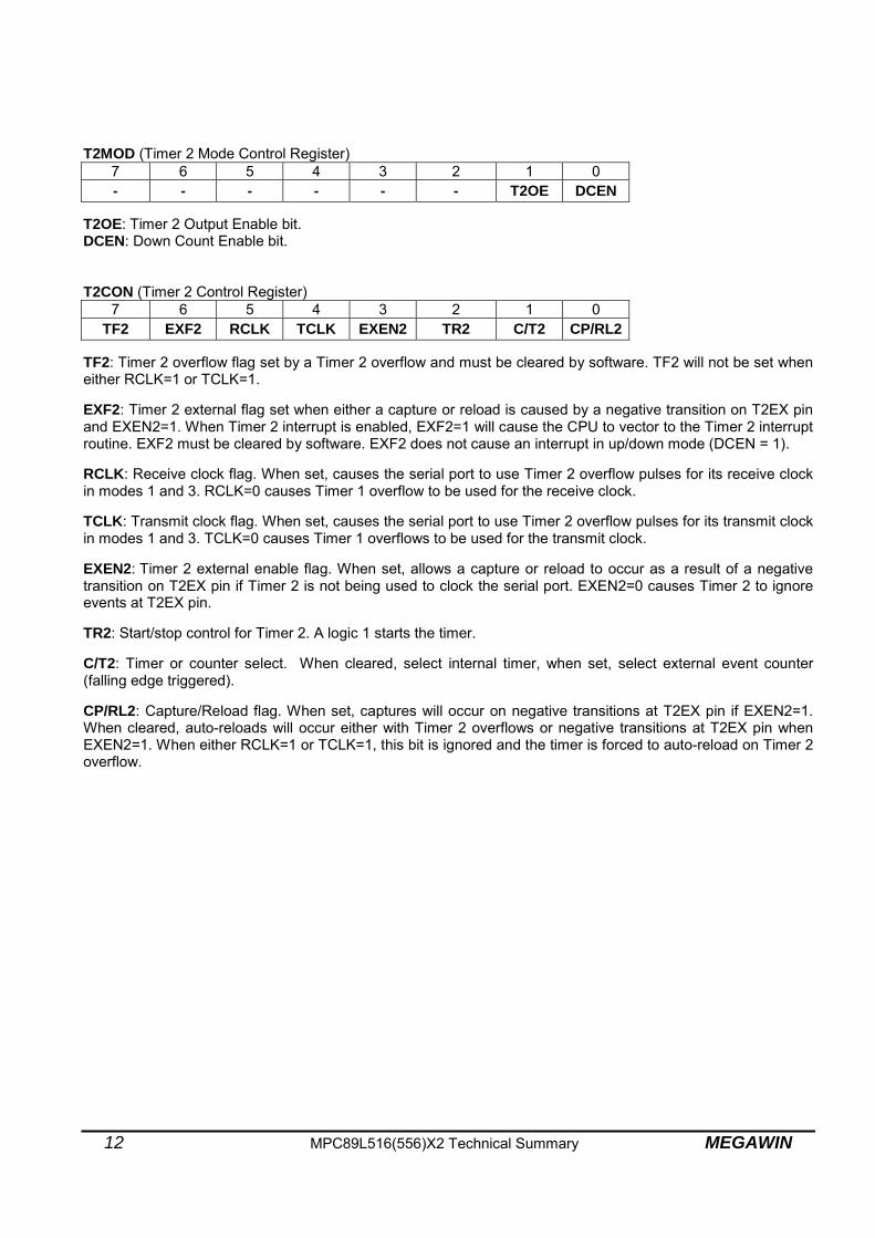
T2MOD (Timer 2 Mode Control Register) 7 6 5 4 3 2 1 0 - - - - - - T2OE DCEN
T2OE: Timer 2 Output Enable bit. DCEN: Down Count Enable bit. T2CON (Timer 2 Control Register)
7 6 5 4 3 2 1 0 TF2 EXF2 RCLK TCLK EXEN2 TR2 C/T2 CP/RL2
TF2: Timer 2 overflow flag set by a Timer 2 overflow and must be cleared by software. TF2 will not be set when either RCLK=1 or TCLK=1. EXF2: Timer 2 external flag set when either a capture or reload is caused by a negative transition on T2EX pin and EXEN2=1. When Timer 2 interrupt is enabled, EXF2=1 will cause the CPU to vector to the Timer 2 interrupt routine. EXF2 must be cleared by software. EXF2 does not cause an interrupt in up/down mode (DCEN = 1). RCLK: Receive clock flag. When set, causes the serial port to use Timer 2 overflow pulses for its receive clock in modes 1 and 3. RCLK=0 causes Timer 1 overflow to be used for the receive clock. TCLK: Transmit clock flag. When set, causes the serial port to use Timer 2 overflow pulses for its transmit clock in modes 1 and 3. TCLK=0 causes Timer 1 overflows to be used for the transmit clock. EXEN2: Timer 2 external enable flag. When set, allows a capture or reload to occur as a result of a negative transition on T2EX pin if Timer 2 is not being used to clock the serial port. EXEN2=0 causes Timer 2 to ignore events at T2EX pin. TR2: Start/stop control for Timer 2. A logic 1 starts the timer. C/T2: Timer or counter select. When cleared, select internal timer, when set, select external event counter (falling edge triggered). CP/RL2: Capture/Reload flag. When set, captures will occur on negative transitions at T2EX pin if EXEN2=1. When cleared, auto-reloads will occur either with Timer 2 overflows or negative transitions at T2EX pin when EXEN2=1. When either RCLK=1 or TCLK=1, this bit is ignored and the timer is forced to auto-reload on Timer 2 overflow.

MEGAWIN MPC89L516(556)X2 Technical Summary 13
7. Programmable Clock-Out A 50% duty cycle clock can be programmed to come out on P1.0. Besides being a regular I/O pin, P1.0 has two alternate functions as shown below. P1.0 Alternate Functions
Function C/T2 (T2CON.1) T2OE (in T2MOD, bit 1)
Timer 2 external clock input (T2) 1 0 50% duty cycle clock output 0 1 To configure the Timer/Counter2 as a clock generator, bit C/T2 (T2CON.1) must be cleared and bit T2OE (in T2MOD, bit 1) must be set. Of course, bit TR2 (T2CON.2) also must be set to start the timer. The Clock-Out frequency depends on the oscillator frequency and the reload value of Timer 2 capture registers (RCAP2H, RCAP2L) as shown in this equation:
n x (65536-[RCAP2H,RCAP2L])Operating Frequency
where, n=4 for 12T mode n=2 for 6T mode
In the Clock-Out mode, Timer 2 roll-overs will not generate an interrupt. This is similar to when it is used as a baud-rate generator. It is possible to use Timer 2 as a baud-rate generator and a clock generator simultaneously. Note that the baud-rate, however, and the clock-out frequency will be the same. T2MOD (Timer 2 Mode Control Register)
7 6 5 4 3 2 1 0 - - - - - - T2OE DCEN
T2OE: Timer 2 Output Enable bit. DCEN: Down Count Enable bit.

14 MPC89L516(556)X2 Technical Summary MEGAWIN
8. Enhanced UART 8.1 Frame Error Detection Hardware will set the FE bit (SCON.7) when an invalid stop bit is detected. The FE bit is not cleared by valid frames but should be cleared by software. The SMOD0 bit (in PCON, bit 6) must be set to enable access to the FE bit. SCON (Serial Port Control Register)
7 6 5 4 3 2 1 0 SM0/FE SM1 SM2 REN TB8 RB8 TI RI
SM0/FE:
SM0: Serial Port Mode bit0 (while SMOD0=0). FE: Frame Error bit (while SMOD0=1).
PCON (Power Control Register)
7 6 5 4 3 2 1 0 SMOD SMOD0 - POF GF1 GF0 PD IDL
SMOD0: 0 to let SCON.7=SM0, and 1 to let SCON.7=FE. POF: Power-ON Flag.
8.2 Automatic Address Recognition Automatic Address Recognition is a feature which allows the UART to recognize certain addresses in the serial bit stream by using hardware to make the comparisons. This feature saves a great deal of software overhead by eliminating the need for the software to examine every serial address which passes by the serial port. This feature is enabled by setting the SM2 bit in SCON. In the 9 bit UART modes, mode 2 and mode 3, the Receive Interrupt flag (RI) will be automatically set when the received byte contains either the “Given” address or the “Broadcast” address. The 9-bit mode requires that the 9th information bit is a 1 to indicate that the received information is an address and not data. Automatic address recognition is shown in the following figure. The 8 bit mode is called Mode 1. In this mode the RI flag will be set if SM2 is enabled and the information received has a valid stop bit following the 8 address bits and the information is either a Given or Broadcast address.
MEGAWIN MPC89L516(556)X2 Technical Summary 15
Mode 0 is the Shift Register mode and SM2 is ignored. Using the Automatic Address Recognition feature allows a master to selectively communicate with one or more slaves by invoking the Given slave address or addresses. All of the slaves may be contacted by using the Broadcast address. Two special Function Registers are used to define the slave’s address, SADDR, and the address mask, SADEN. SADEN is used to define which bits in the SADDR are to be used and which bits are “don’t care”. The SADEN mask can be logically ANDed with the SADDR to create the “Given” address which the master will use for addressing each of the slaves. Use of the Given address allows multiple slaves to be recognized while excluding others. The following examples will help to show the versatility of this scheme: Slave 0
SADDR = 1100 0000 SADEN = 1111 1101 Given = 1100 00X0
Slave 1
SADDR = 1100 0000 SADEN = 1111 1110 Given = 1100 000X
In the above example SADDR is the same and the SADEN data is used to differentiate between the two slaves. Slave 0 requires a 0 in bit 0 and it ignores bit 1. Slave 1 requires a 0 in bit 1 and bit 0 is ignored. A unique address for Slave 0 would be 1100 0010 since slave 1 requires a 0 in bit 1. A unique address for slave 1 would be 1100 0001 since a 1 in bit 0 will exclude slave 0. Both slaves can be selected at the same time by an address which has bit 0 = 0 (for slave 0) and bit 1 = 0 (for slave 1). Thus, both could be addressed with 1100 0000. In a more complex system the following could be used to select slaves 1 and 2 while excluding slave 0: Slave 0
SADDR = 1100 0000 SADEN = 1111 1001 Given = 1100 0XX0
Slave 1 SADDR = 1110 0000 SADEN = 1111 1010 Given = 1110 0X0X
Slave 2 SADDR = 1110 0000 SADEN = 1111 1100 Given = 1110 00XX
In the above example the differentiation among the 3 slaves is in the lower 3 address bits. Slave 0 requires that bit 0 = 0 and it can be uniquely addressed by 1110 0110. Slave 1 requires that bit 1 = 0 and it can be uniquely addressed by 1110 0101. Slave 2 requires that bit 2 = 0 and its unique address is 1110 0011. To select Slaves 0 and 1 and exclude Slave 2 use address 1110 0100, since it is necessary to make bit 2 = 1 to exclude slave 2. The Broadcast Address for each slave is created by taking the logical OR of SADDR and SADEN. Zeros in this result are trended as don’t-cares. In most cases, interpreting the don’t-cares as ones, the broadcast address will be FF hexadecimal. Upon reset SADDR (SFR address 0A9H) and SADEN (SFR address 0B9H) are leaded with 0s. This produces a given address of all “don’t cares” as well as a Broadcast address of all “don’t cares”. This effectively disables the Automatic Addressing mode and allows the micro-controller to use standard 80C51 type UART drivers which do not make use of this feature.

16 MPC89L516(556)X2 Technical Summary MEGAWIN
MEGAWIN MPC89L516(556)X2 Technical Summary 17
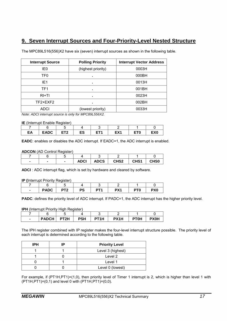
9. Seven Interrupt Sources and Four-Priority-Level Nested Structure The MPC89L516(556)X2 have six (seven) interrupt sources as shown in the following table.
Interrupt Source Polling Priority Interrupt Vector Address
IE0 (highest priority) 0003H
TF0 . 000BH
IE1 . 0013H
TF1 . 001BH
RI+TI . 0023H
TF2+EXF2 . 002BH
ADCI (lowest priority) 0033H Note: ADCI interrupt source is only for MPC89L556X2. IE (Interrupt Enable Register)
7 6 5 4 3 2 1 0 EA EADC ET2 ES ET1 EX1 ET0 EX0
EADC: enables or disables the ADC interrupt. If EADC=1, the ADC interrupt is enabled. ADCON (AD Control Register)
7 6 5 4 3 2 1 0 - - - ADCI ADCS CHS2 CHS1 CHS0
ADCI : ADC interrupt flag, which is set by hardware and cleared by software. IP (Interrupt Priority Register)
7 6 5 4 3 2 1 0 - PADC PT2 PS PT1 PX1 PT0 PX0
PADC: defines the priority level of ADC interrupt. If PADC=1, the ADC interrupt has the higher priority level. IPH (Interrupt Priority High Register)
7 6 5 4 3 2 1 0 - PADCH PT2H PSH PT1H PX1H PT0H PX0H
The IPH register combined with IP register makes the four-level interrupt structure possible. The priority level of each interrupt is determined according to the following table.
IPH IP Priority Level 1 1 Level 3 (highest) 1 0 Level 2 0 1 Level 1 0 0 Level 0 (lowest)
For example, if (PT1H,PT1)=(1,0), then priority level of Timer 1 interrupt is 2, which is higher than level 1 with (PT1H,PT1)=(0,1) and level 0 with (PT1H,PT1)=(0,0).

18 MPC89L516(556)X2 Technical Summary MEGAWIN
10. Wake-up from Power-down by External Interrupt Entering power-down mode, which is invoked by software, can save even more power. In power-down mode, the oscillator is stopped and the instruction that invokes power-down is the last instruction executed. And, the SFRs and on-chip RAM/XRAM retain their values. Either hardware reset or external interrupt (/INT0 or /INT1) can be used to exit from power-down mode. Hardware reset initializes all the SFRs but does not change the on-chip RAM/XRAM, while external interrupt allows both the SFRs and the on-chip RAM/XRAM to retain their values. To properly exit from power-down mode, the external interrupt which is selected for waking up CPU must be enabled before power-down. After power-down, trigger the selected external interrupt to wake up the CPU. Once the interrupt is serviced, the next instruction (after RETI) to be executed will be the one following the instruction that invoked the power-down mode. Note, this instruction must be a “NOP”. Sample code for Wake-up-from-power-down (/INT0 is used in this code)
;****************************************************************************************** ; Wake-up-from-power-down by /INT0 interrupt ;****************************************************************************************** INT0 BIT 0B2H ;P3.2 EA BIT 0AFH ;IE.7 EX0 BIT 0A8H ;IE.0 CSEG AT 0000h JMP start ; CSEG AT 0003h ;INT0 interrupt vector, address=0003h JMP IE0_isr IE0_isr: CLR EX0 ;... do something ;... RETI ; start: ;... ;... SETB INT0 ;pull high P3.2 CLR IE0 ;clear INT0 interrupt flag SETB IT0 ;may select falling-edge/low-level triggered SETB EA SETB EX0 ;enable INT0 interrupt ORL PCON,#02h ;invoke power-down ;... Now, CPU is in power-down mode ;... Wait for an external falling-edge on INT0-pin ;... NOP ;! Note: here must be a NOP wake_up: ;If INT0(P3.2) is triggered by a falling-edge, ; the MCU will wake up, and enter "IE0_isr", ;then return here to run continuously ! ;... ;... ;

MEGAWIN MPC89L516(556)X2 Technical Summary 19
11. Watchdog Timer (WDT) The WDT is intended as a recovery method in situations where the CPU may be subjected to software upset. The WDT consists of a 15-bit free-running counter, a 8-bit prescaler and the WDT control register (WDTCR). The WDT is disabled at reset. To enable the WDT, user must set ENW bit in the WDTCR. When the WDT is enabled, it will increment every machine cycle (12 clocks in 12T mode, and 6 clocks in 6T mode), and the user needs to service it by writing 1 to the CLRW bit to avoid WDT overflow. When the 15-bit counter overflows, the chip reset signal will reset the MCU. WDTCR (Watch-Dog-Timer Control Register)
7 6 5 4 3 2 1 0 - - ENW CLRW WIDL PS2 PS1 PS0
Note: This is a Write-only register. ENW: Set/clear this bit to enable/disable the WDT. CLRW: Write 1 to this bit to clear WDT, and this bit is automatically cleared by H/W after WDT is cleared. WIDL: Clear this bit (!! Set this bit for MPC89L(E)51~515) to let WDT keep counting while the MCU is in the Idle mode. PS2~PS1: Used to determine the prescaler value.
WDT Block Diagram
15-bit counter Chip resetwhen overflow
CLRW
clear
Prescaler
PS2,PS1,PS0
2
4
8
16
64
32
128
256
ENW
Clock source:Fosc/12, or Fosc/6
1: in Idle mode0: otherwise
WIDL

20 MPC89L516(556)X2 Technical Summary MEGAWIN
WDT overflow period The WDT overflow period is determined by the following equation:
(N x Prescaler x 215) / Fosc, where: N=12 for 12T mode, N=6 for 6T mode. The following table shows the WDT overflow period for MCU running at 12MHz. The period is the maximum interval for user to clear the WDT to prevent from chip reset. Example of WDT Overflow Period, @Fosc=12MHz
PS2 PS1 PS0 Prescaler value 12T mode 6T mode
0 0 0 2 65.536 ms 32.768 ms
0 0 1 4 131.072 ms 65.536 ms
0 1 0 8 262.144 ms 131.072 ms
0 1 1 16 524.288 ms 262.144 ms
1 0 0 32 1.048 s 524.288 ms
1 0 1 64 2.097 s 1.048 s
1 1 0 128 4.194 s 2.097 s
1 1 1 256 8.389 s 4.194 s
Sample code for Watchdog Timer Condition: MCU runs at 12MHz and at 6T mode Target: WDT Overflow Period = 524.288ms WDTCR_buf DATA 30h ;declare a buffer for WDTCR ;(because WDTCR is a Write-only register) start: ;... ;... MOV WDTCR_buf,#00h ;clear buffer for WDTCR ANL WDTCR_buf,#0F8h ;(PS2,PS1,PS0)=(1,0,0), prescaler=32 ORL WDTCR_buf,#04h ;@12MHz/6T, WDT_Overflow_Period=524.288ms MOV WDTCR,WDTCR_buf ; ORL WDTCR_buf,#20h ;enable WDT MOV WDTCR,WDTCR_buf ; main_loop: ORL WDTCR_buf,#10h ;clear WDT MOV WDTCR,WDTCR_buf ; ;... ;... JMP main_loop ANL WDTCR_buf,#0DFh ;disable WDT MOV WDTCR,WDTCR_buf ;

MEGAWIN MPC89L516(556)X2 Technical Summary 21
12. Reduced EMI Mode Set the AO bit (in AUXR, bit 0) will turn off the ALE output unless the CPU needs to access external data memory access or run out of external program memory. This may reduce EMI (Electro Magnetic Interference) in some degree. AUXR (Auxiliary Register)
7 6 5 4 3 2 1 0 - - - - - - - AO
AO: Set to turn off ALE output.

22 MPC89L516(556)X2 Technical Summary MEGAWIN
13. 12T Mode and 6T Mode The standard 8051 MCU can only run at 12T mode ( each machine-cycle has 12 clocks ), while the MPC89L516(556)X2 can also run at 6T mode ( each machine-cycle has only 6 clocks ). Its performance is twice that of 12T mode at the same Fosc. To enable 6T mode, program 0 to EN6T bit in OR1 by the WRITER. Note: After whole-chip erasing (including Option Registers), this bit becomes 1, so the CPU will run at 12T mode. While the CPU runs out of external program (with /EA pin pulled low), only 12T mode is supported regardless of EN6T bit. Timing Calculation While the MCU runs at 6T-mode and at Fosc, the user may regard it as 12T-mode and at Fosc x 2. So, all MCU’s timing (including internal and external) calculation can be based on Fosc x 2. For example,
Suppose that the MCU runs at 6T-mode and Fosc=18MHz, we can regard it as a standard 8051 running at 36MHz. So, we will get (1) One machine cycle has 1 / 36MHz x 12 = 0.33us (2) ALE output frequency = 36MHz / 6 = 6MHz (3) External program/data accessing timing, I/O timing and internal Timer/counter timing are calculated on the base of 36MHz.

MEGAWIN MPC89L516(556)X2 Technical Summary 23
14. In-System-Programming (ISP) This MCU’s program memory is made of Flash memory, which has In-System-Programming (ISP) capability. In-System-Programming allows the MCU to alter its program memory, in the actual end product, under software control. This feature opens up a range of applications that need the ability to field update the application firmware. Several special function registers are related to ISP: ISPCR: ISP control register
IFMT: ISP mode select register
IFADRH: ISP Flash address high register
IFADRL: ISP Flash address low register
IFD: ISP Flash data register
SCMD: ISP sequential command register (filled sequentially with 0x46h then 0xB9h to trigger ISP operation) ISPCR (ISP Control Register)
7 6 5 4 3 2 1 0 ISPEN SWBS SWRST - - ICK2 ICK1 ICK0
ISPEN: Set to 1 to enable ISP function.
SWBS: Software boot select. Set/Cleared to select ISP-memory/AP-memory to boot from after reset. See Section 14-7.
SWRST: Write 1 to trigger S/W reset.
ICK2-0: Set programming time of ISP. See Section 14-6. ISP Mode Select Table
IFMT value ISP Mode
0 Standby
1 Read
2 Byte Program
3 Page Erase

24 MPC89L516(556)X2 Technical Summary MEGAWIN
14-1 ISP-memory is Allocated As shown in Figure 14a, the ISP-memory is allocated. To run the “ISP code”, the CPU should boot from the ISP-memory. Two methods are used to boot from the ISP-memory. Figure 14b and Figure 14c demonstrate them. Figure 14a. ISP-memory is Allocated (“ISP code” is placed in ISP-memory)
AP-memory
ISP-memory
0000h
FFFFh
ISP_start_address
Applicationcode
ISP code
Total Flash Memory64KB - ISPsize
64KB
0KB~8KB
Notes: (a) “ISP_start_address” is determined by OR0 (Option Register 0). (b) Use the WRITER to program the “ISP code” into the ISP-memory beginning with “ISP_start_address”.

MEGAWIN MPC89L516(556)X2 Technical Summary 25
Figure 14b. Boot from ISP-memory through AP-memory
Now,CPU will boot from AP-memory,and run "Application code".
Start
SWBS=1 (select boot from ISP-memory)SWRST=1 (trigger S/W reset)
ISPEN=1 (enable ISP function),and initialize ISPCR[2:0]
Do ISP programmingto update the "Application code"
Now,CPU will re-boot from ISP-memory,and run "ISP code".
End
Run "Application code"normally......
Check the user-definedISP condition, do ISP?
YES
NO
Power on or H/W reset (RST-pin)(while PIN_EN=1 and ISP-memory exists)

26 MPC89L516(556)X2 Technical Summary MEGAWIN
Figure 14c. Boot from ISP-memory Directly
Now,CPU will boot from ISP-memory,and run "ISP code".
Start
ISPEN=1 (enable ISP function),and initialize ISPCR[2:0]
Do ISP programmingto update the "Application code"
End
May release P1.0 & P1.1
Power on or H/W reset (RST-pin)(while PIN_EN=0, ISP-memory exists and P1.0 & P1.1 shorted to Gnd)

MEGAWIN MPC89L516(556)X2 Technical Summary 27
14-2 ISP-memory not Allocated As shown in Figure 14d, ISP-memory is not allocated. In this condition, the “ISP code” can be embedded anywhere in the AP-memory. Figure 14e shows how to run the “ISP code” for this configuration. Figure 14d. ISP-memory not allocated (“ISP code” is embedded in AP-memory)
0000h
FFFFh
Applicationcode
ISP code
embeded in AP-memory
Total Flash Memory64KB
AP-memory64KB
Notes:
(a) “ISP code” can be embedded anywhere in the AP-memory.

28 MPC89L516(556)X2 Technical Summary MEGAWIN
Figure 14e. Run “ISP code”, which is embedded at AP-memory
Jump to "ISP code".
Check the user-definedISP condition, do ISP?
YES
Run "Application code"normally......
NO
End
Start
ISPEN=1 (enable ISP function),and initialize ISPCR[2:0]
Do ISP programmingto update the "Application code"
Power on or H/W reset (RST-pin)(while ISP_EN=1 and ISP-memory not exists)
Now, CPU will boot from AP-memory.

MEGAWIN MPC89L516(556)X2 Technical Summary 29
14-3 An Example for the User-defined ISP Condition The user-defined ISP condition, for example, may be:
When just power on, P1.0 and P1.1 are simultaneously shorted to ground for more than 100ms.
If user intends to do ISP, he must execute the following steps:
Step1) Short P1.0 and P1.1 to ground, then power on. Step2) Last for more than 100ms, then release P1.0 and P1.1 for their normal function. Step3) Do ISP operation.
Once the ISP condition is satisfied, the ISP operation is executed from label “do_ISP”, otherwise go to label “not_do_ISP”. The following code shows this example. Start: . .
MOV R0,#100 ;check if really do ISP ? chk_do_ISP: ; JB P1.0,not_do_ISP ; JB P1.1,not_do_ISP ; CALL delay_1ms ; DJNZ R0,chk_do_ISP ; JMP do_ISP ; do_ISP: . . . not_do_ISP: . . .
delay_1ms: . . RET

30 MPC89L516(556)X2 Technical Summary MEGAWIN
14-4 Operation Flow of ISP Figure 14f~14h show the flow chart for the various ISP modes used in the “ISP code”. Figure 14f. Flow Chart for “Erase”
Page_address=0
ISPEN=1 (enable ISP function),and initialize ISPCR[2:0]
Checkend of Page?
YES
NO
Start
IFADRH= High-byte of Page_addressIFADRL= Low-byte of Page_address
SCMD=0x46, then SCMD=0xB9(trigger ISP processing by sequentialwriting)
IFMT=0x03 (select Page Erase Mode)
Page_address=Page_address+0x0200(Increment Page_address,512 bytes per page)
End

MEGAWIN MPC89L516(556)X2 Technical Summary 31
Figure 14g. Flow Chart for “Program”
ISPEN=1 (enable ISP function),and initialize ISPCR[2:0]
Start
Byte_address=0
Checkend of address?
YES
NO
IFADRH= High-byte of Byte_addressIFADRL= Low-byte of Byte_addressIFD=data (to be programmed)
SCMD=0x46, then SCMD=0xB9(trigger ISP processing by sequentialwriting)
IFMT=0x02 (select Byte Program Mode)
Increment Byte_address
End

32 MPC89L516(556)X2 Technical Summary MEGAWIN
Figure 14h. Flow Chart for “Read/Verify”
ISPEN=1 (enable ISP function),and initialize ISPCR[2:0]
Start
Byte_address=0
Check end of address?
YES
NO
IFADRH= High-byte of Byte_addressIFADRL= Low-byte of Byte_address
SCMD=0x46, then SCMD=0xB9(trigger ISP processing by sequentialwriting)
Increment Byte_address
YES
Compare got data(in IFD) with wanted data,the same?
NO
IFMT=0x01 (select Read Mode)
ISP passISP fail

MEGAWIN MPC89L516(556)X2 Technical Summary 33
14-5 Demo Code for the “ISP code”
;****************************************************************************************** ; ISP modes ;****************************************************************************************** IFD DATA 0E2h IFADRH DATA 0E3h IFADRL DATA 0E4h IFMT DATA 0E5h SCMD DATA 0E6h ISPCR DATA 0E7h ; MOV ISPCR,#10000001b ;ISPCR.7=1, enable ISP ;ISPCR[2:0]=001, for Fosc=20MHz ;============================================================================= ; 1. Page Erase Mode (512 bytes per page) ;============================================================================= MOV IFMT,#03h ;select Page Erase Mode MOV IFADRH,?? ;fill page address in IFADRH & IFADRL MOV IFADRL,?? ; MOV SCMD,#46h ;trigger ISP processing MOV SCMD,#0B9h ; ;Now in processing...(CPU will halt here until complete) ;... ;============================================================================= ; 2. Byte Program Mode ;============================================================================= MOV IFMT,#02h ;select Byte Program Mode MOV IFADRH,?? ;fill byte address in IFADRH & IFADRL MOV IFADRL,?? ; MOV IFD,?? ;fill the data to be programmed in IFD MOV SCMD,#46h ;trigger ISP processing MOV SCMD,#0B9h ; ;Now in processing...(CPU will halt here until complete) ;... ;============================================================================= ; 3. Read Mode ;============================================================================= MOV IFMT,#01h ;select Read Mode MOV IFADRH,?? ;fill byte address in IFADRH & IFADRL MOV IFADRL,?? ; MOV SCMD,#46h ;trigger ISP processing MOV SCMD,#0B9h ; ;Now in processing...(CPU will halt here until complete) ;... MOV A,IFD ;data will be in IFD ;

34 MPC89L516(556)X2 Technical Summary MEGAWIN
14-6 Programming Time Setting ISPCR (ISP Control Register)
7 6 5 4 3 2 1 0 ISPEN SWBS SWRST - - ICK2 ICK1 ICK0
ICK2-0: Set programming time of ISP. See the following table for their setting in several Fosc ranges.
14-7 Which Program Memory to Boot from ISPCR (ISP Control Register)
7 6 5 4 3 2 1 0 ISPEN SWBS SWRST - - ICK2 ICK1 ICK0
SWBS: Software boot select. Set/Cleared to select ISP-memory/AP-memory to boot from after reset.
SWRST: Write 1 to trigger S/W reset.
PIN_EN (OR0, bit-3) ISP-memory*1 SWBS
(ISPCR, bit-6)Power-on reset H/W reset (RST-pin pulled high)
S/W reset (write 1 to SWRST bit) WDT reset (Watch-dog Timer overflows)
1 1 0 AP-memory AP-memory
1 1 1 AP-memory ISP-memory
1 0 0 AP-memory AP-memory
1 0 1 AP-memory AP-memory
0 1 0
if P1.1&P1.0 shorted to GND ISP-memory
else AP-memory
AP-memory
0 1 1
if P1.1&P1.0 shorted to GND ISP-memory
else AP-memory
ISP-memory
0 0 0 AP-memory AP-memory
0 0 1 AP-memory AP-memory
Note:
1. The value 1 in the column ISP-memory means ISP-memory exists (not zero byte), while 0 means not exists (zero byte).
2. For the ISPCR register, the bits ISPEN and SWBS will be initialized to its reset value only by power-on reset. The other resets won’t initialize these two bits. So, for example, if ISP-memory exists (not zero byte) and SWBS is set to 1 by firmware before H/W reset, S/W reset or WDT reset come, then the MCU will re-boot from ISP-memory after these resets.
Fosc ICK2 ICK1 ICK0
20~45 MHz 0 0 0
10~20 MHz 0 0 1
5~10 MHz 0 1 0
0~5 MHz 0 1 1

MEGAWIN MPC89L516(556)X2 Technical Summary 35
15. Non-volatile Data Application using ISP Regardless of the ISP-memory is allocated or not allocated, any Flash page (with 512 bytes) in the 64KB Flash memory can be erased, programmed and read by using the ISP, as described in Section 14-4. This useful feature can be applied to the application where data must be kept after power off. Thus, there is no need to use an external EEPROM for saving non-volatile data.
To update the non-volatile data, user should take the following steps:
Step1) Save the whole non-volatile data page (512 bytes) to a buffer (with size of 512 bytes). Step2) Update some specific bytes in the buffer. Step3) Erase this non-volatile data page. Step4) Program the updated data out of the buffer to this page.
Usually, there is not enough internal RAM for this buffer except using external RAM. So, we recommend users use the on-chip 256 bytes of XRAM as the buffer (of course, there should be no user data saved here). So, one 512-byte Flash page can save only 256 bytes of non-volatile data due to the limitation of XRAM’s size. If more non-volatile data are needed, use another Flash page to save one more 256 bytes.

36 MPC89L516(556)X2 Technical Summary MEGAWIN
16. Power-ON Flag The Power-On Flag (POF) is set by hardware when the VDD level rises from 0. The POF bit can be set or cleared by software and thus allows user to determine if the start of CPU is cool (from power-on) or warm (from hardware reset or Watchdog Timer reset). PCON (Power Control Register)
7 6 5 4 3 2 1 0 SMOD SMOD0 - POF GF1 GF0 PD IDL
SMOD0: Cleared for SCON.7=SM0, and set for SCON.7=FE. POF: Power-ON Flag.

MEGAWIN MPC89L516(556)X2 Technical Summary 37
17. Analog-to-Digital Converter (Only for MPC89L556X2) The Analog-to-Digital Converter (ADC) in the MPC89L556X2 adopts an 8-bit-resolution design, and has eight multiplexed analog inputs. The needed references VREF+ and VREF- are internally tied to VDD and GND, respectively, thus keep pin compatible with the standard 8051. This ADC is specially designed for low speed application, such as key-scanning, temperature detection, .., and so on. Three SFRs are involved in using the ADC, the ADCON, P1SF and ADC. Before starting A-to-D conversion, the analog input channel should be selected previously. For example, to select P1.2 as the analog input channel, the bits (CHS2,CHS1,CHS0) in ADCON must be programmed with (0,1,0), and bit ADCH2 in P1SF must be set to 1 to enable P1.2’s alternate function (as ADC input). Now, user can start the A-to-D conversion by setting ADCS bit in ADCON. The converter takes around 7.5 machine cycles to sample the analog input and 9.5 machine cycles for conversion process. So, total 17 machine cycles are needed regardless of the operating frequency. Once the conversion is finished, the hardware will automatically clear ADCS bit, load the digital result into the ADC register for user’s reading and set the ADC interrupt flag (ADCI) simultaneously. User can check if the conversion is finished by polling ADCI flag. Or, if ADC interrupt is enabled, the CPU will enter its Interrupt Service Routine by jumping to the interrupt vector 0x0033 when the conversion is finished. ADCON (AD Control Register)
7 6 5 4 3 2 1 0 - - - ADCI ADCS CHS2 CHS1 CHS0
CHS2~CHS0: Channel selection bits. CHS2 CHS1 CHS0 ADC analog input channel 0 0 0 P1.0 0 0 1 P1.1 0 1 0 P1.2 0 1 1 P1.3 1 0 0 P1.4 1 0 1 P1.5 1 1 0 P1.6 1 1 1 P1.7 ADCS : ADC start bit, which must not be. (Note! Don’t clear it by software at any time.)
ADCI : ADC interrupt flag, which is set by hardware and cleared by software. P1SF (P1 Special Function for A/D analog input)
7 6 5 4 3 2 1 0 ADCH7 ADCH6 ADCH5 ADCH4 ADCH3 ADCH2 ADCH1 ADCH0
Set bit ADCHx to enable the special function of P1.x, as the ADC analog input channel. Clear bit ADCHx to disable the special function of P1.x, as the normal GPIO. The following is a sample F/W code for using the ADC.

38 MPC89L516(556)X2 Technical Summary MEGAWIN
;****************************************************************************************** ; Using the ADC ;****************************************************************************************** P1SF DATA 097h ;register address ADCON DATA 0C5h ; ADC DATA 0C6h ; ;... ; CALL sel_ADC0 ;channel 0 ANL ADCON,#0EFh ;clear ADCI flag ORL ADCON,#08h ;set ADCS bit to start A-to-D conversion wait_ADC_complete: MOV A,ADCON ;check ADCI flag to test if conversion finished JNB ACC.4,wait_ADC_complete ANL ADCON,#0EFh ;clear ADCI flag ;Note! Don’t clear the ADCS bit by software ;... ; sel_ADC0: MOV P1,#0FFh MOV P1SF,#00000001b ;use P1.0 as ADC input MOV ADCON,#00000000b ;select channel 0 RET sel_ADC1: MOV P1,#0FFh MOV P1SF,#00000010b ;use P1.1 as ADC input MOV ADCON,#00000001b ;select channel 1 RET sel_ADC2: MOV P1,#0FFh MOV P1SF,#00000100b ;use P1.2 as ADC input MOV ADCON,#00000010b ;select channel 2 RET sel_ADC3: MOV P1,#0FFh MOV P1SF,#00001000b ;use P1.3 as ADC input MOV ADCON,#00000011b ;select channel 3 RET sel_ADC4: MOV P1,#0FFh MOV P1SF,#00010000b ;use P1.4 as ADC input MOV ADCON,#00000100b ;select channel 4 RET sel_ADC5: MOV P1,#0FFh MOV P1SF,#00100000b ;use P1.5 as ADC input MOV ADCON,#00000101b ;select channel 5 RET sel_ADC6: MOV P1,#0FFh MOV P1SF,#01000000b ;use P1.6 as ADC input MOV ADCON,#00000110b ;select channel 6 RET sel_ADC7: MOV P1,#0FFh MOV P1SF,#10000000b ;use P1.7 as ADC input MOV ADCON,#00000111b ;select channel 7 RET

MEGAWIN MPC89L516(556)X2 Technical Summary 39
17-1 Special Notes The reference voltages VREF+ and VREF- are internally tied to VDD-pin and GND-pin, respectively. So, it is necessary and important to keep the power as clean as possible. In Figure 17a & Figure 17b, X-axis and Y-axis represent digital result (0~255) and analog input (0~3.3V), respectively. Figure 17a shows the ADC curves of 3 chips, which operate at the same frequency (12MHz). These curves are almost the same, which means different chips have a uniform transfer curve. The linear slope of the ADC curve is (255-0) / (3.25-0.05), unit: digital-counts per Volt. Figure 17b, however, shows the non-uniform characteristic of a chip operating at different frequencies (2MHz~30MHz), which exhibits offsets existing between curves. Although the ADC H/W of MPC89L556X2 adopts an 8-bit-resolution design, it only means the maximum resolution is up to 12.8mV (derived from 3.3V/256), however, it doesn’t mean that all the span of 0V~3.3V can be used. As shown in Figure 17b, zero analog input doesn’t guarantee zero digital output, and non-maximum analog input (3.2V) might get maximum digital output (255). For this reason, we recommend user to use 0.3V~3.0V of the span for safe design. Figure 17a. Different chips operate at the same frequency (almost the same)

40 MPC89L516(556)X2 Technical Summary MEGAWIN
Figure 17b. One chip operates at different frequencies (offset exists between curves)

MEGAWIN MPC89L516(556)X2 Technical Summary 41
17-2 An Practical Application: Key-scanning using ADC This practical example illustrates in detail how to design key-scanning (with 8 keys) by ADC. Suppose P1.0 is used as the ADC input channel. Figure 17c. Schematic
P1.0
MPC89L556X2
VDD
GND
Key5 Key6 Key7 Key8
3.3V
Vi
R5 R6 R7R
V2 V3 V4
V5 V6 V7 V8
V1
Key2 Key3 Key4
R2 R3 R4R R1
Key1
Figure 17d. Key Voltages and Digital Boundaries
V8=0V
V2=2.70V
V3=2.35V
V5=1.30V
V6=0.95V
V7=0.60V
V4=2.00V
V1=3.05V
Vno-key=1.65V
ADC>230Detected as Key1
34<ADC<62Detected as Key7
62<ADC<90Detected as Key6
90<ADC<118Detected as Key5
146<ADC<174Detected as Key4
174<ADC<202Detected as Key3
202<ADC<230Detected as Key2
ADC<34Detected as Key8
0.78V ADC=62
1.13V ADC=90
0.43V ADC=34
3.3V
Key Voltages
2.18V ADC=174
2.88V ADC=230
2.53V ADC=202
Key Boundariesanalog digital
1.83V ADC=146
1.48V ADC=118
118<ADC<146No key pressed

42 MPC89L516(556)X2 Technical Summary MEGAWIN
Find R1~R7 and the Digital Boundaries While no key pressed, Vi=VDD/2=3.3/2=1.65 volt While only key1 pressed, Vi=V1= 3.3R / (R+R||R1) volt While only key2 pressed, Vi=V2= 3.3R / (R+R||R2) volt While only key3 pressed, Vi=V3= 3.3R / (R+R||R3) volt While only key4 pressed, Vi=V4= 3.3R / (R+R||R4) volt While only key5 pressed, Vi=V5= 3.3(R||R5) / (R+R||R5) volt While only key6 pressed, Vi=V6= 3.3(R||R6) / (R+R||R6) volt While only key7 pressed, Vi=V7= 3.3(R||R7) / (R+R||R7) volt While only key8 pressed, Vi=V8= 0 volt From the above equations, we may obtain: R1= R(3.3-V1) / (2V1-3.3) for V1>1.65 R2= R(3.3-V2) / (2V2-3.3) for V2>1.65 R3= R(3.3-V3) / (2V3-3.3) for V3>1.65 R4= R(3.3-V4) / (2V4-3.3) for V4>1.65 R5= RV5 / (3.3-2V5) for V5<1.65 R6= RV6 / (3.3-2V6) for V6<1.65 R7= RV7 / (3.3-2V7) for V7<1.65 See Figure 17d, suppose that R and key voltages V1~V7 are chosen as R=10KΩ, V1=3.05V, V2=2.70V, V3=2.35V, V4=2.00V, V5=1.30V, V6=0.95V and V7=0.60V, then R1~R7 can be determined. They are R1=893Ω, R2=2.86KΩ, R3=6.79KΩ, R4=18.57KΩ, R5=18.57KΩ, R6=6.79KΩ and R7=2.86KΩ. And, the analog boundaries can be determined by finding the middle value of each two consecutive key voltages (including Vno-key), thus we can also obtain the digital boundaries “ideally” by: 255*(analog_boundary)/3.20. ADC Calibration by Software Itself Figure 17b shows the non-uniform characteristic of a chip operating at different frequencies, so the ADC value must be calibrated to become the “calibrated value”. The calibration process is as follows. When MCU starts running and no key pressed (now, Vi=1.65V), make the software do the first AD conversion to get the no-key ADC value, say ADCno-key, then subtract it from 131 ( derived from 255x1.65/3.20 ) to find the ADCdelta, i.e., ADCdelta=131–ADCno-key. From now on, once AD conversion is finished, we must add it with ADCdelta to get the calibrated value, which is to be compared with the digital boundaries for key detection. After calibration process, the ADC values won’t depend on operating frequencies and different chips. Thus, correct key scanning is possible no matter what operating frequency and no matter which chip is used .

MEGAWIN MPC89L516(556)X2 Technical Summary 43
Software Flow Chart
Start
Keynot pressed
select P1.0 as input channel
do AD conversion, get ADC
do AD conversion, get ADCno-keyand ADCdelta=131-ADCno-key
do Calibration,ADC=ADC+ADCdelta
compare ADC with theDigital Boundaries to checkwhich key is pressed
do the key service routine
Keypressed

44 MPC89L516(556)X2 Technical Summary MEGAWIN
18. Option Registers OR0 (Option Register 0)
7 6 5 4 3 2 1 0 ISP-memory Setting PIN_EN MOVCL SB LOCK
It can only be programmed by the WRITER. [Bit7..4] Used for ISP-memory setting, refer to the following “ISP-memory Setting Table”.
PIN_EN 0: When power-on or H/W reset (RST-pin), H/W will force CPU to boot from ISP-memory if ISP-memory exists and P1.1 & P1.0 are shorted to GND. 1: (No action)
MOVCL 0: MOVC instruction executed from external program memory is disabled for security. 1: MOVC is always available.
SB 0: Code dumped on Writer is scrambled for security. 1: Code dumped on Writer is not scrambled.
LOCK 0: Code dumped on Writer is locked to 0xFF for security. 1: Code dump on Writer is not locked.
ISP-memory Setting Table
(Bit7,Bit6,Bit5,Bit4) ISP_start_address ISP-memory size (Bytes) AP-memory size (Bytes)
(1,1,1,1) (No ISP-memory) 0 64K (1,1,1,0) 0xFC00 1K 63K (1,1,0,1) 0xFA00 1.5K 62.5K (1,1,0,0) 0xF800 2K 62K (1,0,1,1) 0xF600 2.5K 61.5K (1,0,1,0) 0xF400 3K 61K (1,0,0,1) 0xF200 3.5K 60.5K (1,0,0,0) 0xF000 4K 60K (0,1,1,1) 0xEE00 4.5K 59.5K (0,1,1,0) 0xEC00 5K 59K (0,1,0,1) 0xEA00 5.5K 58.5K (0,1,0,0) 0xE800 6K 58K (0,0,1,1) 0xE600 6.5K 57.5K (0,0,1,0) 0xE400 7K 57K (0,0,0,1) 0xE200 7.5K 56.5K (0,0,0,0) 0xE000 8K 56K
OR1 (Option Register 1)
7 6 5 4 3 2 1 0 - - - - - EN6T - -
It can only be programmed by the WRITER. EN6T
0: MCU runs at 6T mode (each machine-cycle has 6 clocks) 1: MCU runs at 12T mode (each machine-cycle has 12 clocks)

MEGAWIN MPC89L516(556)X2 Technical Summary 45
19. Flash Memory Configuration
AP-memory
ISP-memory
0000h
FFFFh
ISP_start_address
Applicationcode
ISP code
Total Flash Memory64KB-ISPsize
64KB
0KB~8KBdetermined by OR0
(or None if no ISP)

46 MPC89L516(556)X2 Technical Summary MEGAWIN
20. XTAL Oscillating Requirement and ALE Output Frequency 20-1 XTAL Oscillating Requirement As shown in the Oscillating Circuit, to achieve successful and exact oscillating, the values for C1, C2 and R1 are recommended as below.
X1 < 2MHz 2~3MHz 4~9MHz 10~18MHz 19~26MHz 27~34MHz 35~39MHz 40~43MHz 44~48MHz
C1, C2 > 51pF 47pF 20pF 10pF - 10pF 10pF 10pF 5pF
R1 - - - - - 6.8KΩ 5.1KΩ 3.3KΩ 3.3KΩ
Note: (1) ‘-’ means no need. (2) C1 and C2 include the parasitic capacitance in the PCB. Oscillating Circuit
XTAL2
C1
X1
C2
R1
MPC89L516(556)X2
XTAL1
20-2 ALE Output Frequency At 12T-mode, if the XTAL oscillating is successful and correct, the ALE output frequency will be Fosc / 6 (as that of the standard 8051). While at 6T-mode, it will be Fosc*2 / 6. For example,
If Fosc=24MHz, the ALE output frequency is 4MHz and 8MHz for 12T-mode and 6T-mode, respectively.

MEGAWIN MPC89L516(556)X2 Technical Summary 47
21. Power Consumption @VDD=3.3V, 25°C
Notes: (1) Inop : The IDD current when the MCU executes the following instructions:
Loop: NOP JMP Loop
(2) Iidle : The IDD current when the MCU is in its idle mode. (3) Ipwdn : The IDD current when the MCU is in its power-down mode.
12T mode 6T mode Fosc
Inop (mA)
Iidle (mA)
Ipwdn(uA)
Inop (mA)
Iidle (mA)
Ipwdn (uA)
4MHz 5.6 2.2 6.0 2.4 6MHz 6.0 2.5 6.8 2.8 8MHz 6.5 2.9 7.7 3.3 10MHz 6.7 2.8 8.3 3.3 12MHz 7.1 2.9 9.0 3.6 16MHz 7.6 3.2 10.7 4.4 20MHz 8.2 3.5 11.7 4.6 24MHz 9.3 4.1 13.3 5.4 25MHz 10.2 4.2 13.5 5.4 27MHz 10.3 4.7 14.5 6.1 30MHz 11.3 5.3 15.9 6.8 32MHz 11.5 5.4 16.4 7.0 36MHz 13.2 6.7 18.7 8.6 40MHz 13.7 6.7 19.7 8.8 42MHz 14.5 7.3 20.0 8.7 44MHz 14.4 7.1 21.1 9.4 48MHz 15.0 7.2
< 0.1
22.1 9.6
< 0.1

48 MPC89L516(556)X2 Technical Summary MEGAWIN
22. Notes on Using External Interrupt The way to manage external interrupts may exist a difference between the so-called 8051 compatible MCUs. When the external interrupt, say /INT0, is enabled and is triggered while the CPU is executing "CLR EX0", just after "CLR EX0" is completed: the MPC89L516X2 CPU may enter INT0_isr “once”, while other CPU maybe won't enter INT0_isr. An Example: ORG 0000h JMP main ORG 0003h ;/INT0 interrupt vector JMP INT0_isr ;-------------------------------------------------------------- main: CLR IT0 ;IT0=0, select /INT0 as low-level-triggered SETB EA ;enable /INT0 interrupt SETB EX0 ; ; loop: LCALL check_alarm JMP loop ; check_alarm: ;(Suppose: while “check_alarm” is being executed, it must not be interrupted by /INT0.) PUSH IE ;save IE for the following “CLR EX0” CLR EX0 ;!!! Note: /INT0 interrupt may happen at this time NOP ;!!! insert 3 NOPs here for the case: NOP ; if /INT0 really happens and CPU can run its i.s.r here NOP ; MOV P2,#81h ;(!!! these instructions must not be interrupted by /INT0) MOV P0,#00h ; SET P1.5 ; CLR P1.5 ; MOV P0,#FFh ; CLR P3.7 ; MOV A,P0 ; SETB P3.7 ; POP IE ;restore IE RET ; ;-------------------------------------------------------------- INT0_isr: ;… ;… SETB EX0 ;!!! delete this instruction if have, ; to prevent from /INT0 being enabled again while main program’s ; "CLR EX0" is being executed ;… ;… RETI ;

MEGAWIN MPC89L516(556)X2 Technical Summary 49
23. How to Reduce EMI To reduce EMI (Electro Magnetic Interference) generated by the MCU, the following suggestions are useful: (1) Turn off ALE output as described in Section 12.
(2) Use lower Fosc, e.g., lower than 24MHz. (The lower Fosc is, the lower the EMI will be.)
If the performance of 40MHz@12T-mode is necessary, it is strongly recommended to use 20MHz@6T-mode for lower EMI.
(3) Add series resistors R2 and R3 at XTAL1 and XTAL2, respectively, as shown below.
C1
X1
C2
R1
XTAL2
MPC89L516(556)X2
XTAL1
R2
R3
R2 & R3 resistance
X1 8MHz 12MHz 16MHz 20MHz 24MHz
C1, C2 47pF 47pF 47pF 47pF 47pF
R1 - - - - -
R2, R3 33~680Ω 33~560Ω 33~390Ω 33~300Ω 33~300Ω

50 MPC89L516(556)X2 Technical Summary MEGAWIN
24. UART Baudrate Setting To use Timer 1 as the baudrate generator, follow the steps: 1) T2CON=xx00xxxx, where x means “don’t care” bit.
2) Timer 1 operates at its Mode 2 (8-bit auto-reload), i.e., TMOD=0010xxxx, where x means “don’t care” bit.
3) Find TH1 by:
For 12T-mode, baudrate = 2SMOD x Fosc / ( 32 x 12 x (256 - TH1) ). So, TH1 = 256 - 2SMOD x Fosc / (baudrate x 32x 12).
For 6T-mode, baudrate = 2SMOD x Fosc x 2 / ( 32 x 12 x (256 - TH1) ). So, TH1 = 256 - 2SMOD x Fosc x 2 / (baudrate x 32 x 12).
Where SMOD is bit-7 of the PCON register.
4) Start Timer 1, set bit TR1 in the TCON register. To use Timer 2 as the baudrate generator, follow the steps: 1) T2CON=xx11xxxx, where x means “don’t care” bit.
2) Timer 2 operates at its baudrate generator mode, i.e., T2CON=xx11xxxx, where x means “don’t care” bit.
3) Find [RCAP2H,RCAP2L] by:
For 12T-mode, baudrate = Fosc / ( 2 x 16 x (65536 - [RCAP2H, RCAP2L]) ). So, [RCAP2H, RCAP2L] = 65536 - Fosc / (baudrate x 2 x 16).
For 6T-mode, baudrate = Fosc x 2 / ( 2 x 16 x (65536 - [RCAP2H, RCAP2L]) ). So, [RCAP2H, RCAP2L] = 65536 - Fosc x 2 / (baudrate x 2 x 16).
4) Start Timer 2, set bit TR2 in the T2CON register The popular XTAL frequency used for UART application is 11.0592MHz, 18.432MHz, 22.1184MHz and 36.864MHz. The following tables show the TH1 and [RCAP2H, RCAP2L] values for a variety of the standard baudrate.

MEGAWIN MPC89L516(556)X2 Technical Summary 51
Fosc=11.0592MHz
Fosc=18.432MHz
Timer1 ( TH1 ) Timer2 ( [RCAP2H, RCAP2L] )
12T-mode 6T-mode Baudrate
SMOD=0 SMOD=1 SMOD=0 SMOD=1 12T-mode 6T-mode
300 160 64 64 - 64384 63232
600 208 160 160 64 64960 64384
1200 232 208 208 160 65248 64960
1800 240 224 224 192 65344 65152
2400 244 232 232 208 65392 65248
4800 250 244 244 232 65464 65392
7200 252 248 248 240 65488 65440
9600 253 250 250 244 65500 65464
14400 254 252 252 248 65512 65488
19200 - 253 253 250 65518 65500
38400 - - - 253 65527 65518
57600 - 255 255 254 65530 65524
115200 - - - 255 65533 65530
Timer1 ( TH1 ) Timer2 ( [RCAP2H, RCAP2L] )
12T-mode 6T-mode Baudrate
SMOD=0 SMOD=1 SMOD=0 SMOD=1 12T-mode 6T-mode
300 96 - - - 63616 61696
600 176 96 96 - 64576 63616
1200 216 176 176 96 65056 64576
1800 - - - - 65216 64896
2400 236 216 216 176 65296 65056
4800 246 236 236 216 65416 65296
7200 - - - - 65456 65376
9600 251 246 246 236 65476 65416
14400 - - - - 65496 65456
19200 - 251 251 246 65506 65476
38400 - - - 251 65521 65506
57600 - - - - 65526 65516
115200 - - - - 65531 65526

52 MPC89L516(556)X2 Technical Summary MEGAWIN
Fosc=22.1184MHz
Fosc=36.864MHz
Timer1 ( TH1 ) Timer2 ( [RCAP2H, RCAP2L] )
12T-mode 6T-mode Baudrate
SMOD=0 SMOD=1 SMOD=0 SMOD=1 12T-mode 6T-mode
300 64 - - - 63232 60928
600 160 64 64 - 64384 63232
1200 208 160 160 64 64960 64384
1800 224 192 192 128 65152 64768
2400 232 208 208 160 65248 64960
4800 244 232 232 208 65392 65248
7200 248 240 240 224 65440 65344
9600 250 244 244 232 65464 65392
14400 252 248 248 240 65488 65440
19200 253 250 250 244 65500 65464
38400 - 253 253 250 65518 65500
57600 255 254 254 252 65524 65512
115200 - 255 255 254 65530 65524
Timer1 ( TH1 ) Timer2 ( [RCAP2H, RCAP2L] )
12T-mode 6T-mode Baudrate
SMOD=0 SMOD=1 SMOD=0 SMOD=1 12T-mode 6T-mode
300 - - - - 61696 57856
600 96 - - - 63616 61696
1200 176 96 96 - 64576 63616
1800 - - - - 64896 64256
2400 216 176 176 96 65056 64576
4800 236 216 216 176 65296 65056
7200 - - - - 65376 65216
9600 246 236 236 216 65416 65296
14400 - - - - 65456 65376
19200 251 246 246 236 65476 65416
38400 - 251 251 246 65506 65476
57600 - - - - 65516 65496
115200 - - - - 65526 65516