Application Note 237 Multi-Point VOC Measurement System ......consists of a control/detect unit...
6
Application Note AP-237 02/14/VK RAE Systems by Honeywell 877-723-2878 raesystems.com 1 MULTI-POINT VOC MEASUREMENT SYSTEM USING PIDS FOR PROCESS SAFETY Fixed-system PIDs (photoionization detectors) can be used to monitor VOCs on a continuous, 24-hour basis. Continuous measurement can be useful for both industrial hygiene monitoring of VOCs and process safety, to increase productivity and efficiency. Typically, such PIDs must be hard-wired to a power supply to allow operation. Fixed PIDs are best suited for operation with long-life lamps such as 9.8 eV and 10.6 eV lamps. Because of their relatively short life, 11.7 eV lamps are generally not recommended for continuous operation. VOC monitoring measurement in a facility is necessary for compliance with OSHA regulations 1910.120(h)(1)(i) in order to assure proper selection of engineering controls, work practices and personal protective equipment so that employees are not exposed to levels which exceed permissible exposure limits. Measurement can be reached by installing fixed-system instruments in different locations, but in this case, each instrument should be wired to the charging source or be connected through a network to enable VOC monitoring in a real-time regime. Another approach can be used with multiple sensors and just one PID instrument. The 8 Points VOC Sampling System, with remote gas sampling capability, can detect the VOC concentration at eight different positions in turn, and simultaneously output two 4-20mA analog signals. WORKING PRINCIPLE The 8 Points VOC sampling system consists of two parts, namely a control and detection part and a front-end pre-processing part. The control and detection part (control/detect unit, or CDU) consists of a control/detect unit (including Siemens PLC SIMATIC HMI KTP600 and a touch screen), a PID gas detector (RAEGuard 2 PID), an electromagnetic valve, a water/dust removal system, a jet pump (Venturi effect) using compressed air as its power source, and a blow-back system (red dotted line in Figure 3). This part is integrated in a floor-type stainless-steel case, as shown in Figure 1. Figure 1. Control/detect unit (CDU), view from front (left) In addition, the other part of this system, the front-end pre- processing part (PPU), comprises a dust filter and a flame-proof joint. The dust in the sample gas can be removed to avoid blocking the sampling pipe. The explosion- proof joint can effectively isolate the dangerous area and the safe area, thereby avoiding the potential for an explosion. The PPU is integrated on a stainless- steel mounting plate (as shown in black dotted line in Figure 3), and installed at measurement points through a 2” stand pipe or on a wall-mount, as shown in Figure 2. Figure 2. Front-end of the pre-processing unit (PPU).
Transcript of Application Note 237 Multi-Point VOC Measurement System ......consists of a control/detect unit...
Application Note AP-237 02/14/VK
RAE Systems by Honeywell 877-723-2878 raesystems.com 1
MULTI-POINT VOC MEASUREMENT SYSTEM USING PIDS FOR PROCESS SAFETYFixed-system PIDs (photoionization detectors) can be used to monitor VOCs on a continuous, 24-hour basis. Continuous measurement can be useful for both industrial hygiene monitoring of VOCs and process safety, to increase productivity and efficiency. Typically, such PIDs must be hard-wired to a power supply to allow operation. Fixed PIDs are best suited for operation with long-life lamps such as 9.8 eV and 10.6 eV lamps. Because of their relatively short life, 11.7 eV lamps are generally not recommended for continuous operation.
VOC monitoring measurement in a facility is necessary for compliance with OSHA regulations 1910.120(h)(1)(i) in order to assure proper selection of engineering controls, work practices and personal protective equipment so that employees are not exposed to levels which exceed permissible exposure limits. Measurement can be reached by installing fixed-system instruments in different locations, but in this case, each instrument should be wired to the charging source or be connected through a network to enable VOC monitoring in a real-time regime.
Another approach can be used with multiple sensors and just one PID instrument. The 8 Points VOC Sampling System, with remote gas sampling capability, can detect the VOC concentration at eight different positions in turn, and simultaneously output two 4-20mA analog signals.
WORKING PRINCIPLE
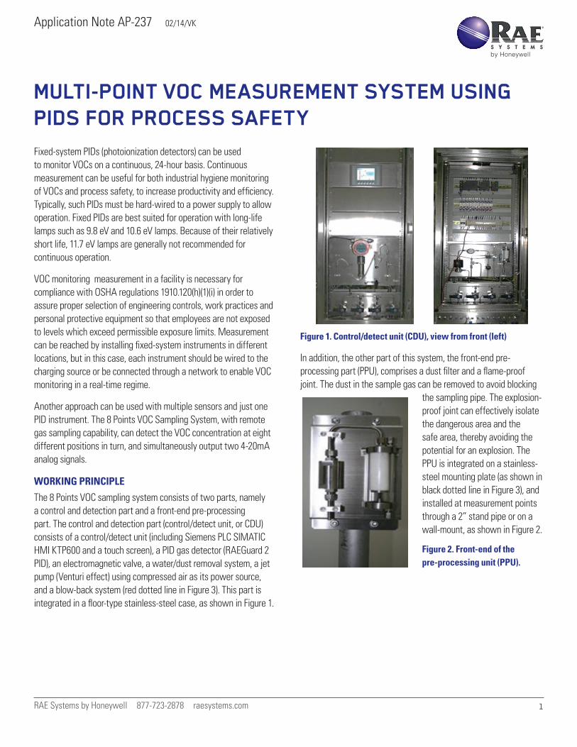
The 8 Points VOC sampling system consists of two parts, namely a control and detection part and a front-end pre-processing part. The control and detection part (control/detect unit, or CDU) consists of a control/detect unit (including Siemens PLC SIMATIC HMI KTP600 and a touch screen), a PID gas detector (RAEGuard 2 PID), an electromagnetic valve, a water/dust removal system, a jet pump (Venturi effect) using compressed air as its power source, and a blow-back system (red dotted line in Figure 3). This part is integrated in a floor-type stainless-steel case, as shown in Figure 1.
Figure 1. Control/detect unit (CDU), view from front (left)
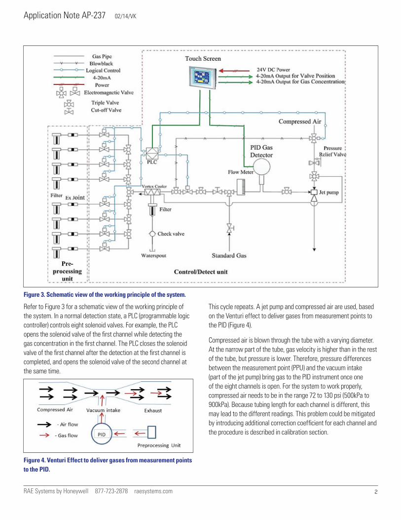
In addition, the other part of this system, the front-end pre-processing part (PPU), comprises a dust filter and a flame-proof joint. The dust in the sample gas can be removed to avoid blocking
the sampling pipe. The explosion-proof joint can effectively isolate the dangerous area and the safe area, thereby avoiding the potential for an explosion. The PPU is integrated on a stainless-steel mounting plate (as shown in black dotted line in Figure 3), and installed at measurement points through a 2” stand pipe or on a wall-mount, as shown in Figure 2.
Figure 2. Front-end of the pre-processing unit (PPU).
Application Note AP-237 02/14/VK
RAE Systems by Honeywell 877-723-2878 raesystems.com 2
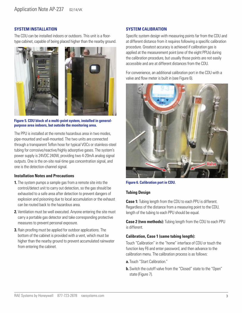
Refer to Figure 3 for a schematic view of the working principle of the system. In a normal detection state, a PLC (programmable logic controller) controls eight solenoid valves. For example, the PLC opens the solenoid valve of the first channel while detecting the gas concentration in the first channel. The PLC closes the solenoid valve of the first channel after the detection at the first channel is completed, and opens the solenoid valve of the second channel at the same time.
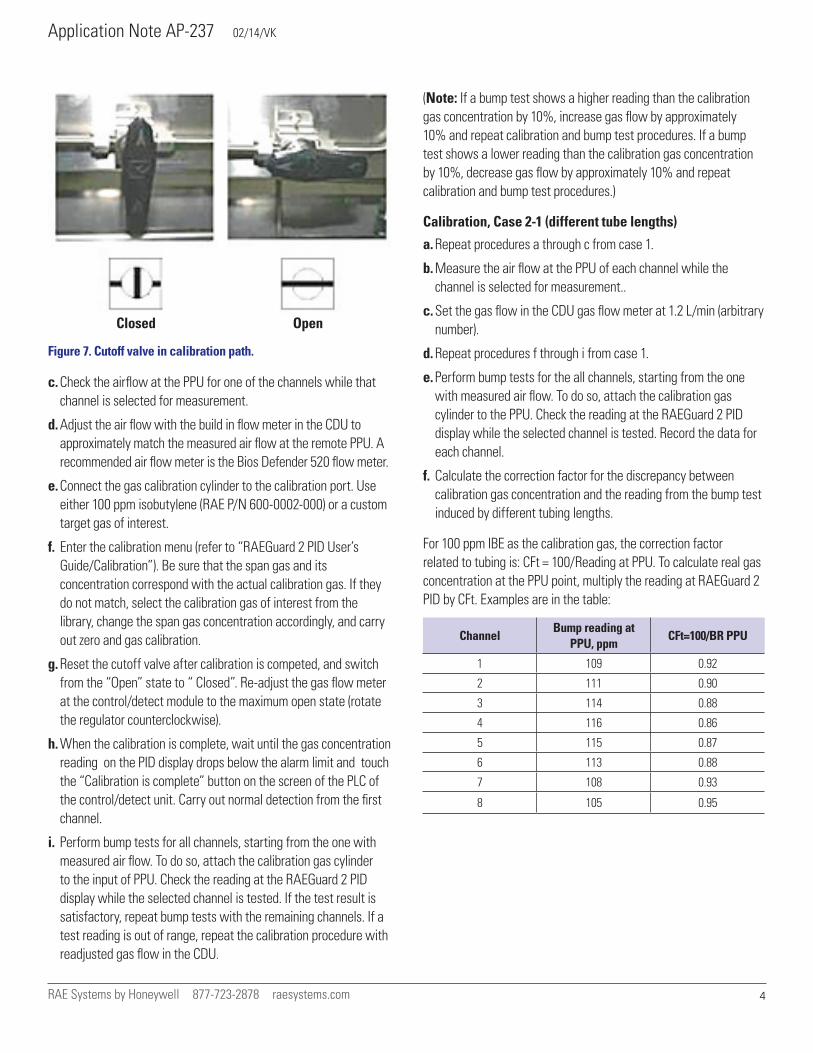
Figure 4. Venturi Effect to deliver gases from measurement points to the PID.
This cycle repeats. A jet pump and compressed air are used, based on the Venturi effect to deliver gases from measurement points to the PID (Figure 4).
Compressed air is blown through the tube with a varying diameter. At the narrow part of the tube, gas velocity is higher than in the rest of the tube, but pressure is lower. Therefore, pressure differences between the measurement point (PPU) and the vacuum intake (part of the jet pump) bring gas to the PID instrument once one of the eight channels is open. For the system to work properly, compressed air needs to be in the range 72 to 130 psi (500kPa to 900kPa). Because tubing length for each channel is different, this may lead to the different readings. This problem could be mitigated by introducing additional correction coefficient for each channel and the procedure is described in calibration section.
Figure 3. Schematic view of the working principle of the system.
Application Note AP-237 02/14/VK
RAE Systems by Honeywell 877-723-2878 raesystems.com 3
SYSTEM INSTALLATION
The CDU can be installed indoors or outdoors. This unit is a floor-type cabinet, capable of being placed higher than the nearby ground.
The PPU is installed at the remote hazardous area in two modes, pipe-mounted and wall-mounted. The two units are connected through a transparent Teflon hose for typical VOCs or stainless-steel tubing for corrosive/reactive/highly adsorptive gases. The system’s power supply is 24VDC 240W, providing two 4-20mA analog signal outputs. One is the on-site real-time gas concentration signal, and one is the detection-channel signal.
Installation Notes and Precautions
1. The system pumps a sample gas from a remote site into the control/detect unit to carry out detection, so the gas should be exhausted to a safe area after detection to prevent dangers of explosion and poisoning due to local accumulation or the exhaust can be routed back to the hazardous area.
2. Ventilation must be well executed. Anyone entering the site must carry a portable gas detector and take corresponding protective measures to prevent personal exposure.
3. Rain proofing must be applied for outdoor applications. The bottom of the cabinet is provided with a vent, which must be higher than the nearby ground to prevent accumulated rainwater from entering the cabinet.
SYSTEM CALIBRATION
Specific system design with measuring points far from the CDU and at different distance from it requires following a specific calibration procedure. Greatest accuracy is achieved if calibration gas is applied at the measurement point (one of the eight PPUs) during the calibration procedure, but usually those points are not easily accessible and are at different distances from the CDU.
For convenience, an additional calibration port in the CDU with a valve and flow meter is built in (see Figure 6).
Tubing Design
Case 1: Tubing length from the CDU to each PPU is different. Regardless of the distance from a measuring point to the CDU, length of the tubing to each PPU should be equal.
Case 2 (two methods): Tubing length from the CDU to each PPU is different.
Calibration, Case 1 (same tubing length):
Touch “Calibration” in the “home” interface of CDU or touch the function key F6 and enter password, and then advance to the calibration menu. The calibration process is as follows:
a. Touch “Start Calibration.”
b. Switch the cutoff valve from the “Closed” state to the “Open” state (Figure 7).
Figure 5. CDU block of a multi-point system, installed in general-purpose area indoors, but outside the monitoring area.
Figure 6. Calibration port in CDU.
Valve
Application Note AP-237 02/14/VK
RAE Systems by Honeywell 877-723-2878 raesystems.com 4
c. Check the airflow at the PPU for one of the channels while that channel is selected for measurement.
d. Adjust the air flow with the build in flow meter in the CDU to approximately match the measured air flow at the remote PPU. A recommended air flow meter is the Bios Defender 520 flow meter.
e. Connect the gas calibration cylinder to the calibration port. Use either 100 ppm isobutylene (RAE P/N 600-0002-000) or a custom target gas of interest.
f. Enter the calibration menu (refer to “RAEGuard 2 PID User’s Guide/Calibration”). Be sure that the span gas and its concentration correspond with the actual calibration gas. If they do not match, select the calibration gas of interest from the library, change the span gas concentration accordingly, and carry out zero and gas calibration.
g. Reset the cutoff valve after calibration is competed, and switch from the “Open” state to “ Closed”. Re-adjust the gas flow meter at the control/detect module to the maximum open state (rotate the regulator counterclockwise).
h. When the calibration is complete, wait until the gas concentration reading on the PID display drops below the alarm limit and touch the “Calibration is complete” button on the screen of the PLC of the control/detect unit. Carry out normal detection from the first channel.
i. Perform bump tests for all channels, starting from the one with measured air flow. To do so, attach the calibration gas cylinder to the input of PPU. Check the reading at the RAEGuard 2 PID display while the selected channel is tested. If the test result is satisfactory, repeat bump tests with the remaining channels. If a test reading is out of range, repeat the calibration procedure with readjusted gas flow in the CDU.
(Note: If a bump test shows a higher reading than the calibration gas concentration by 10%, increase gas flow by approximately 10% and repeat calibration and bump test procedures. If a bump test shows a lower reading than the calibration gas concentration by 10%, decrease gas flow by approximately 10% and repeat calibration and bump test procedures.)
Calibration, Case 2-1 (different tube lengths)
a. Repeat procedures a through c from case 1.
b. Measure the air flow at the PPU of each channel while the channel is selected for measurement..
c. Set the gas flow in the CDU gas flow meter at 1.2 L/min (arbitrary number).
d. Repeat procedures f through i from case 1.
e. Perform bump tests for the all channels, starting from the one with measured air flow. To do so, attach the calibration gas cylinder to the PPU. Check the reading at the RAEGuard 2 PID display while the selected channel is tested. Record the data for each channel.
f. Calculate the correction factor for the discrepancy between calibration gas concentration and the reading from the bump test induced by different tubing lengths.
For 100 ppm IBE as the calibration gas, the correction factor related to tubing is: CFt = 100/Reading at PPU. To calculate real gas concentration at the PPU point, multiply the reading at RAEGuard 2 PID by CFt. Examples are in the table:
ChannelBump reading at
PPU, ppmCFt=100/BR PPU
1 109 0.92
2 111 0.90
3 114 0.88
4 116 0.86
5 115 0.87
6 113 0.88
7 108 0.93
8 105 0.95
Figure 7. Cutoff valve in calibration path.
Closed Open
Application Note AP-237 02/14/VK
RAE Systems by Honeywell 877-723-2878 raesystems.com 5
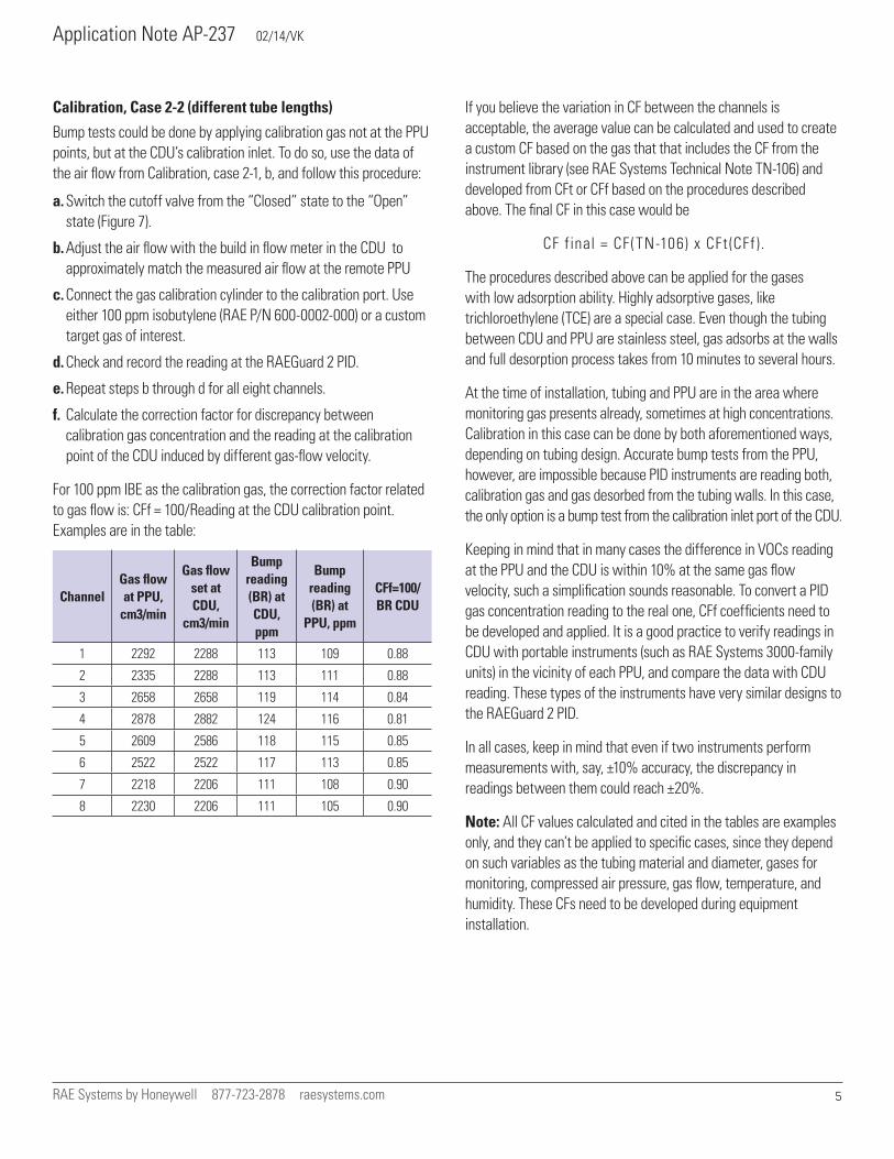
Calibration, Case 2-2 (different tube lengths)
Bump tests could be done by applying calibration gas not at the PPU points, but at the CDU’s calibration inlet. To do so, use the data of the air flow from Calibration, case 2-1, b, and follow this procedure:
a. Switch the cutoff valve from the “Closed” state to the “Open” state (Figure 7).
b. Adjust the air flow with the build in flow meter in the CDU to approximately match the measured air flow at the remote PPU
c. Connect the gas calibration cylinder to the calibration port. Use either 100 ppm isobutylene (RAE P/N 600-0002-000) or a custom target gas of interest.
d. Check and record the reading at the RAEGuard 2 PID.
e. Repeat steps b through d for all eight channels.
f. Calculate the correction factor for discrepancy between calibration gas concentration and the reading at the calibration point of the CDU induced by different gas-flow velocity.
For 100 ppm IBE as the calibration gas, the correction factor related to gas flow is: CFf = 100/Reading at the CDU calibration point. Examples are in the table:
ChannelGas flow at PPU,
cm3/min
Gas flow set at CDU,
cm3/min
Bump reading (BR) at CDU, ppm
Bump reading (BR) at
PPU, ppm
CFf=100/BR CDU
1 2292 2288 113 109 0.88
2 2335 2288 113 111 0.88
3 2658 2658 119 114 0.84
4 2878 2882 124 116 0.81
5 2609 2586 118 115 0.85
6 2522 2522 117 113 0.85
7 2218 2206 111 108 0.90
8 2230 2206 111 105 0.90
If you believe the variation in CF between the channels is acceptable, the average value can be calculated and used to create a custom CF based on the gas that that includes the CF from the instrument library (see RAE Systems Technical Note TN-106) and developed from CFt or CFf based on the procedures described above. The final CF in this case would be
CF final = CF (TN-106) x CFt (CFf ).
The procedures described above can be applied for the gases with low adsorption ability. Highly adsorptive gases, like trichloroethylene (TCE) are a special case. Even though the tubing between CDU and PPU are stainless steel, gas adsorbs at the walls and full desorption process takes from 10 minutes to several hours.
At the time of installation, tubing and PPU are in the area where monitoring gas presents already, sometimes at high concentrations. Calibration in this case can be done by both aforementioned ways, depending on tubing design. Accurate bump tests from the PPU, however, are impossible because PID instruments are reading both, calibration gas and gas desorbed from the tubing walls. In this case, the only option is a bump test from the calibration inlet port of the CDU.
Keeping in mind that in many cases the difference in VOCs reading at the PPU and the CDU is within 10% at the same gas flow velocity, such a simplification sounds reasonable. To convert a PID gas concentration reading to the real one, CFf coefficients need to be developed and applied. It is a good practice to verify readings in CDU with portable instruments (such as RAE Systems 3000-family units) in the vicinity of each PPU, and compare the data with CDU reading. These types of the instruments have very similar designs to the RAEGuard 2 PID.
In all cases, keep in mind that even if two instruments perform measurements with, say, ±10% accuracy, the discrepancy in readings between them could reach ±20%.
Note: All CF values calculated and cited in the tables are examples only, and they can’t be applied to specific cases, since they depend on such variables as the tubing material and diameter, gases for monitoring, compressed air pressure, gas flow, temperature, and humidity. These CFs need to be developed during equipment installation.
Application Note AP-237 02/14/VK
RAE Systems by Honeywell 877-723-2878 raesystems.com 6
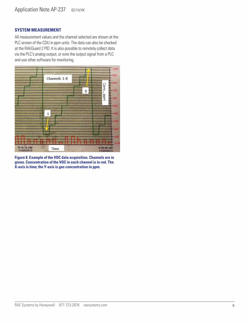
SYSTEM MEASUREMENT
All measurement values and the channel selected are shown at the PLC screen of the CDU in ppm units. The data can also be checked at the RAEGuard 2 PID. It is also possible to remotely collect data via the PLC’s analog output, or wire the output signal from a PLC and use other software for monitoring.
Figure 8. Example of the VOC data acquisition. Channels are in green. Concentration of the VOC in each channel is in red. The X-axis is time; the Y-axis is gas concentration in ppm.