APPLICATION IDENTIFICATION DESCRIPTION LUBRICATION ...bbscomp.com/george/manual.pdf · 1997 MANUAL...
18
1997 MANUAL TRANSMISSIONS Ford (Mazda) M5OD-R2 5-Speed Overhaul APPLICATION TRANSMISSION APPLICATION IDENTIFICATION The M5OD identification tag is located on left side of transmission main case. Vehicle certification label, located on left side door lock pillar, lists applicable transmission identification codes under TRANS space. M5OD-R2 transmission is identified by an "M" code on label. DESCRIPTION This Mazda built transmission is a fully synchronized, 5-speed, top shift transmission. Fifth gear is an overdrive ratio. All gear changes, including reverse are accomplished with synchronizer sleeves. Transmission case is aluminum alloy with steel bearing race inserts. LUBRICATION & ADJUSTMENTS See TRANSMISSION SERVICING article in MANUAL TRANS SERVICE section. TROUBLE SHOOTING See TROUBLE SHOOTING - BASIC PROCEDURE article in GENERAL TROUBLE SHOOTING section. ON-VEHICLE SERVICE GEARSHIFT LEVER REPLACEMENT Removal Shift transmission into Neutral position. Remove transfer case shift lever knob (if equipped). Remove carpet or floor mat to expose transmission shift lever boot screws. Remove transmission shift lever boot screws. Slide boot upward on shift lever to expose transmission shift lever nut and bolt. Remove shift lever nut, bolt and shift lever. Remove inner shift lever boot. Installation Application Transmission Model F150 Pickup M5OD-R2 F250 Pickup M5OD-R2 1997 Ford Pickup F150 1997 MANUAL TRANSMISSIONS Ford (Mazda) M5OD-R2 5-Speed Overhaul 1997 Ford Pickup F150 1997 MANUAL TRANSMISSIONS Ford (Mazda) M5OD-R2 5-Speed Overhaul
Transcript of APPLICATION IDENTIFICATION DESCRIPTION LUBRICATION ...bbscomp.com/george/manual.pdf · 1997 MANUAL...

1997 MANUAL TRANSMISSIONS
Ford (Mazda) M5OD-R2 5-Speed Overhaul
APPLICATION
TRANSMISSION APPLICATION
IDENTIFICATION
The M5OD identification tag is located on left side of transmission main case. Vehicle certification label, located on left side door lock pillar, lists applicable transmission identification codes under TRANS space. M5OD-R2 transmission is identified by an "M" code on label.
DESCRIPTION
This Mazda built transmission is a fully synchronized, 5-speed, top shift transmission. Fifth gear is an overdrive ratio. All gear changes, including reverse are accomplished with synchronizer sleeves. Transmission case is aluminum alloy with steel bearing race inserts.
LUBRICATION & ADJUSTMENTS
See TRANSMISSION SERVICING article in MANUAL TRANS SERVICE section.
TROUBLE SHOOTING
See TROUBLE SHOOTING - BASIC PROCEDURE article in GENERAL TROUBLE SHOOTING section.
ON-VEHICLE SERVICE
GEARSHIFT LEVER REPLACEMENT
Removal
Shift transmission into Neutral position. Remove transfer case shift lever knob (if equipped). Remove carpet or floor mat to expose transmission shift lever boot screws. Remove transmission shift lever boot screws. Slide boot upward on shift lever to expose transmission shift lever nut and bolt. Remove shift lever nut, bolt and shift lever. Remove inner shift lever boot.
Installation
Application Transmission ModelF150 Pickup M5OD-R2F250 Pickup M5OD-R2
1997 Ford Pickup F150
1997 MANUAL TRANSMISSIONS Ford (Mazda) M5OD-R2 5-Speed Overhaul
1997 Ford Pickup F150
1997 MANUAL TRANSMISSIONS Ford (Mazda) M5OD-R2 5-Speed Overhaul
me
Monday, May 11, 2009 7:17:08 PM Page 1 © 2005 Mitchell Repair Information Company, LLC.
me
Monday, May 11, 2009 7:17:12 PM Page 1 © 2005 Mitchell Repair Information Company, LLC.
To install, reverse removal procedure.
EXTENSION HOUSING SEAL
Removal
Remove drive shaft. Using appropriate seal remover, remove extension housing seal.
Installation
Using appropriate seal installer, install NEW seal on extension housing. Lubricate oil seal lip prior to installation. Ensure oil seal drain hole faces downward. Install drive shaft.
EXTENSION HOUSING BUSHING
Extension housing bushing cannot be serviced. If bushing requires service or replacement, extension housing must be replaced as a unit.
REMOVAL & INSTALLATION
See TRANSMISSION REMOVAL & INSTALLATION article MANUAL TRANS SERVICE section.
TRANSMISSION DISASSEMBLY
1. Remove transmission drain plug and drain transmission. Remove top cover assembly and extension housing. Remove speedometer drive gear and steel ball (if equipped). If necessary, remove rear oil passage. Lock transmission into 1st and 3rd gears. Ensure staked areas securing output shaft and countershaft lock nuts are fully released or thread damage will occur. Remove and discard countershaft rear bearing lock nut.
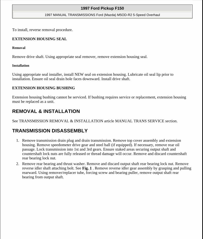
2. Remove rear bearing and thrust washer. Remove and discard output shaft rear bearing lock nut. Remove reverse idler shaft attaching bolt. See Fig. 1 . Remove reverse idler gear assembly by grasping and pulling rearward. Using remover/replacer tube, forcing screw and bearing puller, remove output shaft rear bearing from output shaft.
1997 Ford Pickup F150
1997 MANUAL TRANSMISSIONS Ford (Mazda) M5OD-R2 5-Speed Overhaul
me
Monday, May 11, 2009 7:17:08 PM Page 2 © 2005 Mitchell Repair Information Company, LLC.
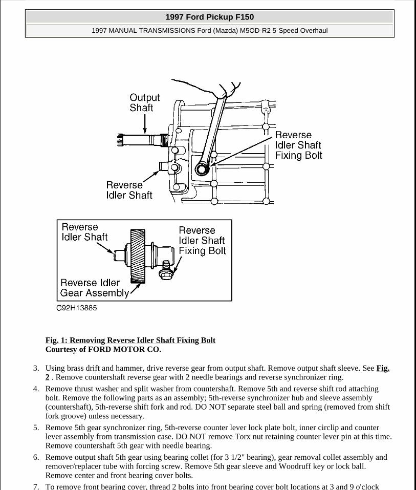
Fig. 1: Removing Reverse Idler Shaft Fixing Bolt Courtesy of FORD MOTOR CO.
3. Using brass drift and hammer, drive reverse gear from output shaft. Remove output shaft sleeve. See Fig. 2 . Remove countershaft reverse gear with 2 needle bearings and reverse synchronizer ring.
4. Remove thrust washer and split washer from countershaft. Remove 5th and reverse shift rod attaching bolt. Remove the following parts as an assembly; 5th-reverse synchronizer hub and sleeve assembly (countershaft), 5th-reverse shift fork and rod. DO NOT separate steel ball and spring (removed from shift fork groove) unless necessary.
5. Remove 5th gear synchronizer ring, 5th-reverse counter lever lock plate bolt, inner circlip and counter lever assembly from transmission case. DO NOT remove Torx nut retaining counter lever pin at this time. Remove countershaft 5th gear with needle bearing.
6. Remove output shaft 5th gear using bearing collet (for 3 1/2" bearing), gear removal collet assembly and remover/replacer tube with forcing screw. Remove 5th gear sleeve and Woodruff key or lock ball. Remove center and front bearing cover bolts.
7. To remove front bearing cover, thread 2 bolts into front bearing cover bolt locations at 3 and 9 o'clock
1997 Ford Pickup F150
1997 MANUAL TRANSMISSIONS Ford (Mazda) M5OD-R2 5-Speed Overhaul
me
Monday, May 11, 2009 7:17:08 PM Page 3 © 2005 Mitchell Repair Information Company, LLC.

positions. Alternately tighten bolts lifting front bearing cover away from transmission case. DO NOT remove plastic scoop ring from input shaft at this time.
8. Remove oil trough from upper transmission case by removing bolt. See Fig. 3 . Pull input shaft forward and remove input shaft bearing. Pull output shaft rearward.
9. Pull input shaft forward and separate it from output shaft assembly. Incline output shaft upward and lift from transmission case. Remove input shaft from transmission case.
10. Remove countershaft front and center bearings by moving countershaft forward and rearward. Pull countershaft rearward to permit clearance for bearing puller behind countershaft front bearing. Remove countershaft front bearing. Remove countershaft through top of transmission case.
Fig. 2: Exploded View Of Rear Housing Components Courtesy of FORD MOTOR CO.
1997 Ford Pickup F150
1997 MANUAL TRANSMISSIONS Ford (Mazda) M5OD-R2 5-Speed Overhaul
me
Monday, May 11, 2009 7:17:08 PM Page 4 © 2005 Mitchell Repair Information Company, LLC.
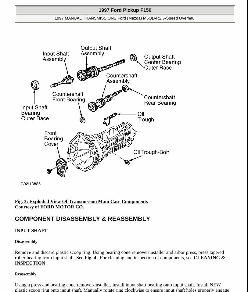
Fig. 3: Exploded View Of Transmission Main Case Components Courtesy of FORD MOTOR CO.
COMPONENT DISASSEMBLY & REASSEMBLY
INPUT SHAFT
Disassembly
Remove and discard plastic scoop ring. Using bearing cone remover/installer and arbor press, press tapered roller bearing from input shaft. See Fig. 4 . For cleaning and inspection of components, see CLEANING & INSPECTION .
Reassembly
Using a press and bearing cone remover/installer, install input shaft bearing onto input shaft. Install NEW plastic scoop ring onto input shaft. Manually rotate ring clockwise to ensure input shaft holes properly engage
1997 Ford Pickup F150
1997 MANUAL TRANSMISSIONS Ford (Mazda) M5OD-R2 5-Speed Overhaul
me
Monday, May 11, 2009 7:17:08 PM Page 5 © 2005 Mitchell Repair Information Company, LLC.
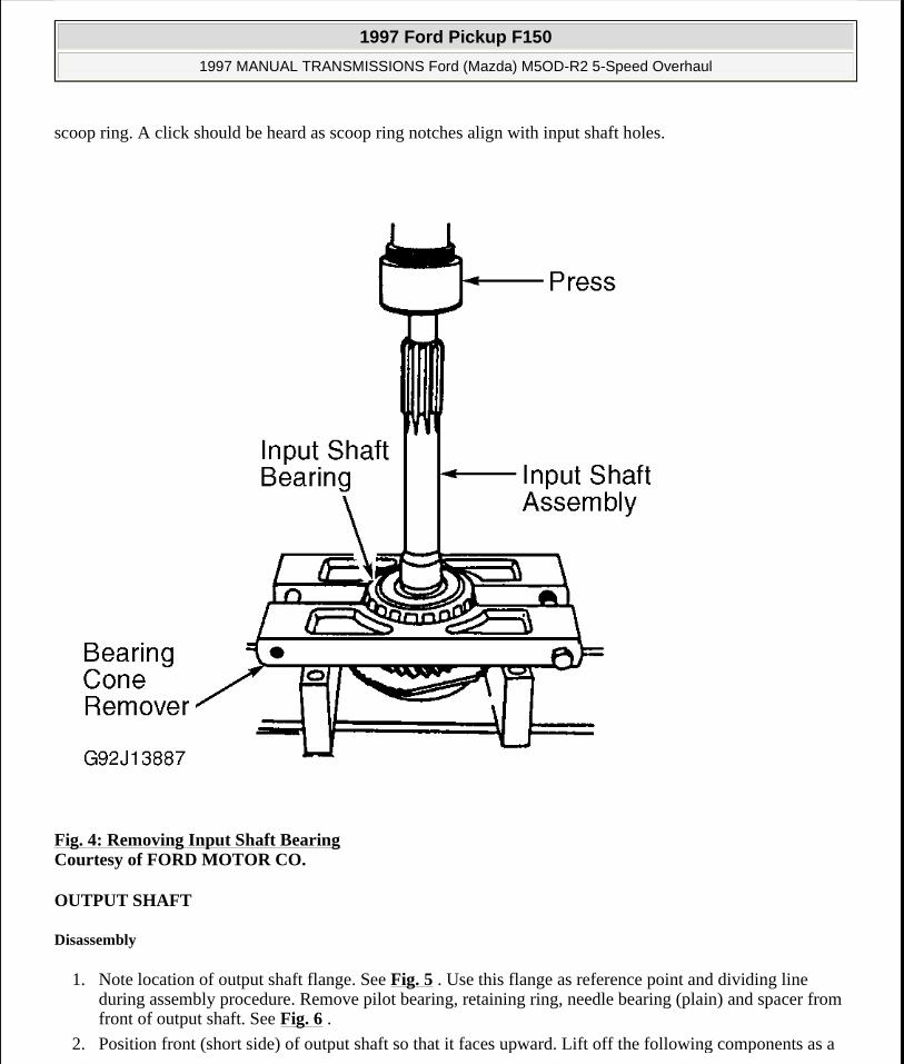
scoop ring. A click should be heard as scoop ring notches align with input shaft holes.
Fig. 4: Removing Input Shaft Bearing Courtesy of FORD MOTOR CO.
OUTPUT SHAFT
Disassembly
1. Note location of output shaft flange. See Fig. 5 . Use this flange as reference point and dividing line during assembly procedure. Remove pilot bearing, retaining ring, needle bearing (plain) and spacer from front of output shaft. See Fig. 6 .
2. Position front (short side) of output shaft so that it faces upward. Lift off the following components as a
1997 Ford Pickup F150
1997 MANUAL TRANSMISSIONS Ford (Mazda) M5OD-R2 5-Speed Overhaul
me
Monday, May 11, 2009 7:17:08 PM Page 6 © 2005 Mitchell Repair Information Company, LLC.

unit; clutch hub and sleeve assembly (3rd-4th), 3rd gear synchronizer ring, 3rd gear and needle bearing. See Fig. 6 .
3. Position output shaft with rear end (long side) facing upward. Position output shaft into press with press cradle contacting lower part of 2nd gear. See Fig. 7 .
4. Press off the following components as a unit; center bearing, 1st gear sleeve, 1st gear and needle bearing, 1st-2nd clutch hub and sleeve assembly, 1st-2nd synchronizer rings, 2nd gear and needle bearing. For cleaning and inspection of components, see CLEANING & INSPECTION .
Fig. 5: Locating Flange On Output Shaft Assembly Courtesy of FORD MOTOR CO.
NOTE: Ensure output shaft flange does not contact or ride upward onto press cradle. Improper positioning of output shaft can cause component damage.
1997 Ford Pickup F150
1997 MANUAL TRANSMISSIONS Ford (Mazda) M5OD-R2 5-Speed Overhaul
me
Monday, May 11, 2009 7:17:08 PM Page 7 © 2005 Mitchell Repair Information Company, LLC.

Fig. 6: Exploded View Of Front Of Output Shaft Courtesy of FORD MOTOR CO.
1997 Ford Pickup F150
1997 MANUAL TRANSMISSIONS Ford (Mazda) M5OD-R2 5-Speed Overhaul
me
Monday, May 11, 2009 7:17:08 PM Page 8 © 2005 Mitchell Repair Information Company, LLC.

Fig. 7: Exploded View Of Rear Of Output Shaft Courtesy of FORD MOTOR CO.
Reassembly
1. Ensure center bearing outer race is installed into transmission case. Position output shaft so that rear (long side) faces upward.
2. Install components onto output shaft in following order; 2nd gear needle bearing, 2nd gear, 2nd gear synchronizer ring, 1st-2nd clutch hub and sleeve assembly, 1st gear synchronizer ring, 1st gear needle bearing, 1st gear, 1st gear sleeve and inner center bearing. Ensure narrow width of 1st-2nd synchronizer faces 2nd gear. See Fig. 7 .
3. Press center bearing onto rear (long side) of output shaft. Position output shaft front (short side) facing upward. Install parts in following order; 3rd gear needle bearing, 3rd gear and 3rd gear synchronizer ring.
4. Mate 3rd-4th clutch hub synchronizer key groove with reference mark on clutch hub sleeve. Install 3rd-4th clutch hub and sleeve with reference mark and long clutch hub flange facing rearward. See Fig. 6 and
1997 Ford Pickup F150
1997 MANUAL TRANSMISSIONS Ford (Mazda) M5OD-R2 5-Speed Overhaul
me
Monday, May 11, 2009 7:17:08 PM Page 9 © 2005 Mitchell Repair Information Company, LLC.

Fig. 11 . Install spacer and retainer on output shaft.
5. Using a feeler gauge, measure clutch hub end play. Adjust 3rd-4th clutch hub end play to .00-.002" (.00-.05 mm) by selecting proper retaining ring. Retaining rings are available in thicknesses of .59-.077" (1.50-1.95 mm) in .002" (.05 mm) increments.
REVERSE IDLER GEAR
Disassembly & Reassembly
1. Remove retaining ring, spacer, idler gear, needle bearing and thrust washer. For cleaning and inspection of components, see CLEANING & INSPECTION .
2. To reassemble, reverse disassembly procedure. Ensure tab on thrust washer mates with groove on reverse idler shaft to prevent rotation of thrust washer. See Fig. 8 .
3. Install original retaining ring onto reverse idler gear shaft. Insert feeler gauge between retaining ring and reverse idler gear to measure reverse idler gear end play. Adjust reverse idler gear end play to .004-.008" (.10-.20 mm). Reverse idler gear retaining rings are available in thicknesses of .059-.075" (1.50-1.90 mm) in .004" (.10 mm) increments.
Fig. 8: Assembling Reverse Idler Gear Courtesy of FORD MOTOR CO.
INPUT SHAFT END PLAY
1. Position transmission with clutch housing facing up. Ensure input shaft bearing is squarely positioned in bore. Using appropriate seal replacer, install front cover oil baffle (if removed). Install countershaft front
1997 Ford Pickup F150
1997 MANUAL TRANSMISSIONS Ford (Mazda) M5OD-R2 5-Speed Overhaul
me
Monday, May 11, 2009 7:17:08 PM Page 10 © 2005 Mitchell Repair Information Company, LLC.

bearing by hand.
2. Using depth micrometer, measure height of input shaft bearing above transmission case, record as Dimension "A". Measure depth of input shaft bearing retainer bore, record as Dimension "B". See Fig. 9 .
3. Calculate input shaft end play as follows; Dimension "B" - (Dimension "A" + shim thickness)=.002-.006" (.05-.15 mm). Select shim to maintain end play within specified limit. See INPUT SHAFT SHIM SELECTION table.
4. Measure depth of countershaft bearing below transmission case, record as Dimension "C". Measure depth of countershaft bearing retainer bore, record as Dimension "D". See Fig. 9 .
5. Calculate countershaft end play as follows; Dimension "C" + (Dimension "D" + shim thickness)=.006-.010" (.15-.25 mm). Select shim to maintain end play within specified limit. See COUNTERSHAFT SPACER SELECTION table.
1997 Ford Pickup F150
1997 MANUAL TRANSMISSIONS Ford (Mazda) M5OD-R2 5-Speed Overhaul
me
Monday, May 11, 2009 7:17:08 PM Page 11 © 2005 Mitchell Repair Information Company, LLC.
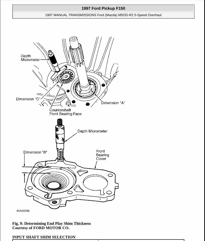
Fig. 9: Determining End Play Shim Thickness Courtesy of FORD MOTOR CO.
INPUT SHAFT SHIM SELECTION
1997 Ford Pickup F150
1997 MANUAL TRANSMISSIONS Ford (Mazda) M5OD-R2 5-Speed Overhaul
me
Monday, May 11, 2009 7:17:08 PM Page 12 © 2005 Mitchell Repair Information Company, LLC.

COUNTERSHAFT SPACER SELECTION
CLEANING & INSPECTION
CLEANING
Wash all parts except seals, in cleaning solvent. Dry all parts with compressed air. DO NOT spin bearings with compressed air.
INSPECTION
Bearings
Inspect bearings and replace if broken, worn or rough. Lubricate cleaned bearing. Hold bearing vertically by
Part No. In. (mm)E8TZ-7029-FA .0551 (1.4)E8TZ-7029-GA .0590 (1.5)E8TZ-7029-HA .0629 (1.6)E8TZ-7029-JA .0669 (1.7)E8TZ-7029-S .0708 (1.8)E8TZ-7029-T .0748 (1.9)E8TZ-7029-U .0787 (2.0)E8TZ-7029-V .0826 (2.1)E8TZ-7029-W .0866 (2.2)E8TZ-7029-X .0905 (2.3)E8TZ-7029-Y .0944 (2.4)E8TZ-7029-Z .0984 (2.5)E8TZ-7029-AA .1023 (2.6)E8TZ-7029-BA .1062 (2.7)E8TZ-7029-CA .1102 (2.8)E8TZ-7029-DA .1141 (2.9)E8TZ-7029-EA .1181 (3.0)
Part No. In. (mm)E8TZ-7C434-K .122 (3.1)E8TZ-7C434-L .125 (3.2)E8TZ-7C434-M .129 (3.3)E8TZ-7C434-N .133 (3.4)E8TZ-7C434-P .137 (3.5)E8TZ-7C434-R .141 (3.6)E8TZ-7C434-S .145 (3.7)E8TZ-7C434-T .118 (3.0)
1997 Ford Pickup F150
1997 MANUAL TRANSMISSIONS Ford (Mazda) M5OD-R2 5-Speed Overhaul
me
Monday, May 11, 2009 7:17:09 PM Page 13 © 2005 Mitchell Repair Information Company, LLC.
inner race and spin outer race by hand. DO NOT spin bearings with compressed air. If roughness or vibration is noticed, bearing should be cleaned and lubricated again and retested. If roughness or vibration is noticed after 3 tests, replace bearing.
Countershaft
Inspect splines and gear teeth for damage or wear. Replace countershaft if bent, damaged or worn.
Input Shaft
Replace input shaft if splines are damaged, needle bearing surfaces are worn or rough, or other bearing surfaces are damaged.
Output Shaft
Mount output shaft in V-blocks. Check runout on shaft at several locations. If runout exceeds .002" (.05 mm), replace output shaft.
Synchronizers
If teeth on synchronizer ring are chipped, broken or worn, replace synchronizer ring. Note that 3rd gear synchronizer is different from others. To check for wear, mount synchronizer to mating gear and measure clearance between gear and synchronizer side faces using a feeler gauge. If clearance is less than .031" (.80 mm), replace synchronizer ring or mating gear.
Check contact surfaces of shift fork and clutch hub sleeve for wear or damage. Using feeler gauge, check shift fork-to-clutch hub sleeve clearance. Clearance should not exceed .031" (.80 mm).
Check operation of clutch hub sleeve installed on hub. Position clutch hub and sleeve horizontally. Lift hub approximately 3/4 of the way off sleeve and release. If hub does not return into sleeve, service as necessary.
TRANSMISSION REASSEMBLY
1. Install countershaft, input shaft and output shaft assemblies into transmission case through top opening. See Fig. 10 .
2. Mate input and output shaft assemblies by positioning them at an upward angle and setting them together. Install output shaft bearing using a brass drift. Ensure center bearing outer races are squarely positioned in bores. Install countershaft center bearing.
NOTE: Ensure needle roller bearing is installed into input shaft and 4th gear synchronizer ring is installed at this time.
1997 Ford Pickup F150
1997 MANUAL TRANSMISSIONS Ford (Mazda) M5OD-R2 5-Speed Overhaul
me
Monday, May 11, 2009 7:17:09 PM Page 14 © 2005 Mitchell Repair Information Company, LLC.
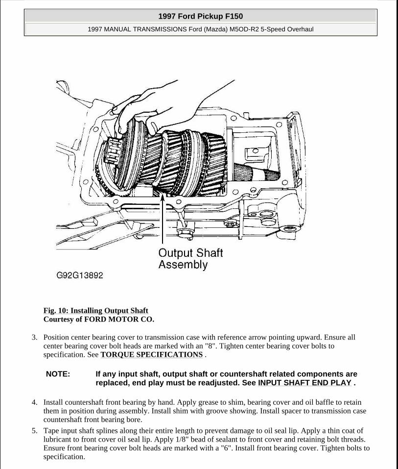
Fig. 10: Installing Output Shaft Courtesy of FORD MOTOR CO.
3. Position center bearing cover to transmission case with reference arrow pointing upward. Ensure all center bearing cover bolt heads are marked with an "8". Tighten center bearing cover bolts to specification. See TORQUE SPECIFICATIONS .
4. Install countershaft front bearing by hand. Apply grease to shim, bearing cover and oil baffle to retain them in position during assembly. Install shim with groove showing. Install spacer to transmission case countershaft front bearing bore.
5. Tape input shaft splines along their entire length to prevent damage to oil seal lip. Apply a thin coat of lubricant to front cover oil seal lip. Apply 1/8" bead of sealant to front cover and retaining bolt threads. Ensure front bearing cover bolt heads are marked with a "6". Install front bearing cover. Tighten bolts to specification.
NOTE: If any input shaft, output shaft or countershaft related components are replaced, end play must be readjusted. See INPUT SHAFT END PLAY .
1997 Ford Pickup F150
1997 MANUAL TRANSMISSIONS Ford (Mazda) M5OD-R2 5-Speed Overhaul
me
Monday, May 11, 2009 7:17:09 PM Page 15 © 2005 Mitchell Repair Information Company, LLC.

6. Install Woodruff key or lock ball, 5th gear sleeve and 5th gear needle bearing onto 5th gear countershaft. To install 5th gear assembly on 2WD, use Gear Installing Spacer (T88T-7025-F). When tool bottoms, add Gear Installing Spacer (T88T-7025-G) and press 5th gear assembly all the way into position. Ensure long flange on 5th gear faces forward.
7. Position 5th and reverse shift lever to transmission and install thrust washer and retaining ring. Apply sealant to counter lever retaining bolt threads. Tighten bolt to specification. If removed, position 5th-reverse shift fork and shift rail to top cover. See Fig. 11 . Insert 5th-reverse shift rail through top cover bore and 5th-reverse shift fork. Install spring and detent ball to lower part of rod.
Fig. 11: Installing 5th-Reverse Shift Fork & Rail Courtesy of FORD MOTOR CO.
8. Assemble 5th-reverse synchronizer hub, sleeve and 5th gear synchronizer ring to 5th-reverse shift fork and rod assembly. Install longer flange, on 5th-reverse hub, sleeve and synchronizer assembly, toward front of transmission. Reference mark on synchronizer sleeve must be installed toward reverse gear. See Fig. 12 .
NOTE: On 4WD vehicles, installation of 5th gear is similar except that Remover/Replacer Tube (T85T-7025-A) and TOD Bearing Remover/Replacer Adapter (T84T-7025-A) are used.
1997 Ford Pickup F150
1997 MANUAL TRANSMISSIONS Ford (Mazda) M5OD-R2 5-Speed Overhaul
me
Monday, May 11, 2009 7:17:09 PM Page 16 © 2005 Mitchell Repair Information Company, LLC.

Fig. 12: Installing Synchronizer Assembly Courtesy of FORD MOTOR CO.
9. Install and mate 5th-reverse shift fork and shift rail assembly to counter lever end. Install assembly in case, aligning threaded fixing bolt bores, in rail and transmission case. Apply sealant to bolt threads and tighten to specification. See TORQUE SPECIFICATIONS . Position oil passage to transmission case. Apply sealant to oil passage bolt threads and tighten to specification.
10. If original clutch hub and/or counter reverse gear are being used, install original split washers onto countershaft and go to step 12). If synchronizer hub has been replaced, install original split washers. Using a feeler gauge, measure 5th-reverse synchronizer hub end play between synchronizer hub and split washers.
11. End play should be 0-0.002" (0-.05 mm). Replace split washers to obtain proper end play. Split washers are available in thicknesses of .12-.14" (3.0-3.5 mm) in .004" (.10 mm) increments. Ensure NEW split washers are matched, having identical thickness. Go to next step.
12. Install reverse synchronizer ring and needle bearing into reverse gear. Install counter reverse gear and needle bearings onto counter shaft as an assembly. Install thrust washer and press forward by hand against shoulder on countershaft.
13. Maintain forward pressure and measure end play with feeler gauge between counter reverse gear and thrust washer. Counter reverse gear end play should be .010-.014" (.25-.36 mm). Replace thrust washer to
1997 Ford Pickup F150
1997 MANUAL TRANSMISSIONS Ford (Mazda) M5OD-R2 5-Speed Overhaul
me
Monday, May 11, 2009 7:17:09 PM Page 17 © 2005 Mitchell Repair Information Company, LLC.

obtain proper end play. Thrust washers are available in thicknesses of .293-.309" (7.45-7.85 mm) in .004" (.10 mm) increments.
14. Temporarily install a spacer in place of countershaft bearing. Loosely install countershaft lock nut to retain components. Install reverse idler gear assembly. Apply sealant to retaining bolt threads. Install bolt and tighten to specification.
15. Drive sleeve and reverse gear assembly onto output shaft, using Gear Replacing Spacer (T88T-7025-G), Shaft Adapter (T75L-7025-P), Shaft Adapter Screw (T75L-7025-K), Remover/Replacer Tube (T75L-7025-B, 2WD or T85T-7025-A, 4WD), nut and washer. Install reverse gear with longer flange facing forward. Install output shaft rear bearing.
16. Remove temporary spacer from countershaft. Install countershaft rear bearing by hand. Ensure bearing is fully seated to avoid damage to output shaft threads.
17. Lock transmission into 1st and 3rd gear. Install NEW output and countershaft lock nuts by hand. Tighten nuts to specification. See TORQUE SPECIFICATIONS . Stake lock nuts to bottom of shaft.
18. Install speedometer drive gear and steel ball (if equipped). Apply 1/8" bead of sealant to case and install transmission extension housing. Place synchronizers in neutral position. DO NOT apply sealant to mating surfaces of top cover or case.
19. If necessary, lightly grease cover gasket to retain in position. Install top cover. Apply sealant to threads of 2 rearmost top cover bolts only. Install remaining bolts without sealant. Tighten bolts to specification. Fill transmission with Mercon automatic transmission fluid.
TORQUE SPECIFICATIONS
TORQUE SPECIFICATIONS Application Ft. Lbs. (N.m)Center Bearing Cover Bolt 14-19 (19-26)Countershaft Lock Nut 94-144 (127-195)Drain Plug 29-43 (39-58)Extension Housing Bolt 24-34 (33-46)Filler Plug 29-43 (39-58)Front Bearing Cover Bolt 12-16 (16-22)Gear Shift Lever Bolt/Nut 12-18 (16-24)Output Shaft Lock Nut 160-203 (217-275)Reverse Idler Shaft Fixing Bolt 58-86 (79-117)Top Cover Bolt 12-16 (16-22)5th-Reverse Shift Rail Bolt 16-22 (22-30)
INCH Lbs. (N.m) Counter Lever Bolt 72-89 (8-10)Front Oil Passage Bolt 72-96 (8-11)Rear Oil Passage Bolt 60-84 (7-9)
1997 Ford Pickup F150
1997 MANUAL TRANSMISSIONS Ford (Mazda) M5OD-R2 5-Speed Overhaul
me
Monday, May 11, 2009 7:17:09 PM Page 18 © 2005 Mitchell Repair Information Company, LLC.