
Application guide TELECOOL
18
Providing indoor climate comfort TELECOOL - THX TELECOOL THX-AGU-0104-E Application guide
Transcript of Application guide TELECOOL
Providing indoor climate comfort
TELECOOL - THX
TELECOOL THX-AGU-0104-E
Application guide
Application Guide Telecool THX - 0104 - E Series - Page 1
Due to LENNOX on going commitment to quality, specifications subject to change without notice and without incurring liability
Our company is a member of theEurovent Certification Programme.
Our products comply withthe European standards.
The manufacturingECOLOGIC™ family ofchillers answers to ISO9001 control qualitysystem. A copy of thecertificate can be get onrequest.
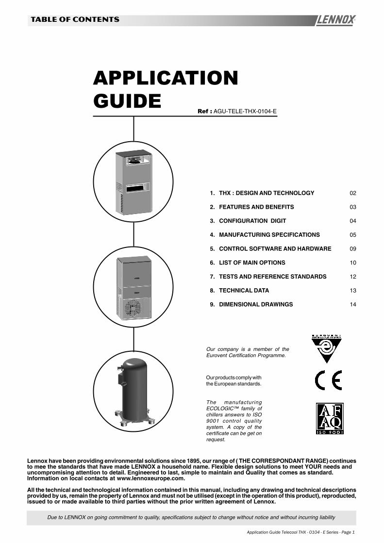
1. THX : DESIGN AND TECHNOLOGY 02
2. FEATURES AND BENEFITS 03
3. CONFIGURATION DIGIT 04
4. MANUFACTURING SPECIFICATIONS 05
5. CONTROL SOFTWARE AND HARDWARE 09
6. LIST OF MAIN OPTIONS 10
7. TESTS AND REFERENCE STANDARDS 12
8. TECHNICAL DATA 13
9. DIMENSIONAL DRAWINGS 14
APPLICATIONGUIDE
TABLE OF CONTENTS
Ref : AGU-TELE-THX-0104-E
Lennox have been providing environmental solutions since 1895, our range of ( THE CORRESPONDANT RANGE) continuesto mee the standards that have made LENNOX a household name. Flexible design solutions to meet YOUR needs anduncompromising attention to detail. Engineered to last, simple to maintain and Quality that comes as standard.Information on local contacts at www.lennoxeurope.com.
All the technical and technological information contained in this manual, including any drawing and technical descriptionsprovided by us, remain the property of Lennox and must not be utilised (except in the operation of this product), reproducted,issued to or made available to third parties without the prior written agreement of Lennox.
Page 2 - Application Guide Telecool THX - 0104 - E
THX : DESIGN AND TECHNOLOGY
THX = Design & Technology
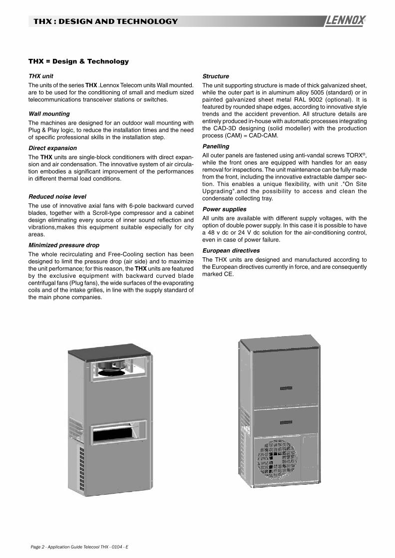
THX unit
The units of the series THX .Lennox Telecom units Wall mounted.are to be used for the conditioning of small and medium sizedtelecommunications transceiver stations or switches.
Wall mounting
The machines are designed for an outdoor wall mounting withPlug & Play logic, to reduce the installation times and the needof specific professional skills in the installation step.
Direct expansion
The THX units are single-block conditioners with direct expan-sion and air condensation. The innovative system of air circula-tion embodies a significant improvement of the performancesin different thermal load conditions.
Reduced noise level
The use of innovative axial fans with 6-pole backward curvedblades, together with a Scroll-type compressor and a cabinetdesign eliminating every source of inner sound reflection andvibrations,makes this equipment suitable especially for cityareas.
Minimized pressure drop
The whole recirculating and Free-Cooling section has beendesigned to limit the pressure drop (air side) and to maximizethe unit performance; for this reason, the THX units are featuredby the exclusive equipment with backward curved bladecentrifugal fans (Plug fans), the wide surfaces of the evaporatingcoils and of the intake grilles, in line with the supply standard ofthe main phone companies.
Structure
The unit supporting structure is made of thick galvanized sheet,while the outer part is in aluminum alloy 5005 (standard) or inpainted galvanized sheet metal RAL 9002 (optional). It isfeatured by rounded shape edges, according to innovative styletrends and the accident prevention. All structure details areentirely produced in-house with automatic processes integratingthe CAD-3D designing (solid modeller) with the productionprocess (CAM) = CAD-CAM.
PanellingAll outer panels are fastened using anti-vandal screws TORX®,while the front ones are equipped with handles for an easyremoval for inspections. The unit maintenance can be fully madefrom the front, including the innovative extractable damper sec-tion. This enables a unique flexibility, with unit ."On SiteUpgrading".and the possibility to access and clean thecondensate collecting tray.
Power suppliesAll units are available with different supply voltages, with theoption of double power supply. In this case it is possible to havea 48 v dc or 24 V dc solution for the air-conditioning control,even in case of power failure.
European directives
The THX units are designed and manufactured according tothe European directives currently in force, and are consequentlymarked CE.
Application Guide Telecool THX - 0104 - E Series - Page 3
FEATURES AND BENEFITS
Features and Benefits
Design vs. Technology?
The THX units introduce a new plant model featured by apleasant design matched with a rational arrangement of thecomponents and an excellent assembly compactness. The sin-gle-compressor unit reduced dimensions enable to install twounits on a 2.20-mwall, as for the shelters including the ministations for wireless telephony. The special Lennox concept ofSFT .Side Free-Cooling Technology. enables to reach a realoperation under partial load conditions with possiblesimultaneous mechanical cooling, even when the twounits operate together. The two-compressor series .2. matchesthe safety of the two machines with the inexpensiveness of thesingle unit, with a power range covering about 80% of theinstalled. All units are factory tested by using automatic systemsbased on objective .in-out. criteria and are ready to be installedand started by simple wiring on site.
Start-Up
The holes arranged on the rear flange enable the machine/swall-mounting; the condensate discharge is to be arranged andthe power supply is to be connected. In case of units with three-phase main supply, check the phase correct sequence (theindicator on the phase sequence relay in the electric boardswitches on): in case of wrong sequence, themP control recordsan alarmand does not enable the compressor start. The startingprocedure is operated by pressing the key .ON. on the controlkeyboard.
Handling
The THX units can be handled by fitting belts under the baseand paying attention to make them pass through the suppliedanti-tilting eyebolts, fastened in the upper side part.
Noise levels
The THX units include the exclusive use of ventilation solutions,featured by a low emitted noise level making these conditionerscompatible with city installations.The support structure, thepanels and the fastening systems are designed to reducevibrations and their transmission as low frequency soundemissions as much as possible.
Energy efficiency
The highest possible energy efficiency has been the main targetin the whole thermo-dynamic and aeraulic designing. Therefrigerating circuit is featured by the use of .rolling piston. or.Scroll. compressors with top reliability and (optional) possibilityof replacing the traditional lamination component with anelectronically-controlled electric valve: this brings a reducedenergy consumption by 50% when the outer temperature lowersbelow 20¢XC and, above all, when the direct free-cooling is
not possible.The aeraulic circuit implies the use of centrifugalfans with backward curved blades, featured by a very highreaction degree, it is thus possible to remove the scroll andthe relevant energy losses in the dynamic-statical conversion;all used fans can be equipped with .brushless. motor withpermanent magnets and relevant switching electronics, thatcan be directly powered by an emergency mains at 48 V dc or24 V dc. In this case, the dc motor efficiency matches with thefan efficiency, thus reaching outstanding energy results (over45%). The SFT® concept developed by Lennox achieves, aswell as exceptional aeraulic performance, a true exploitationeven together with the mechanical cycle: this contributesremarkably to reduce energy costs in the range of outertemperatures between the inner set point and TFT (Total Free-Cooling temperature).
Emergency situations
All units can be equipped with dual supply, main supply and"dc" supply.
• Main supply:- Compressor- Heating- Condensing section fan
• 24 V dc or 48 V dc supply:- evaporating section fan- Microprocessor- Damper servomotor
In case of mains failure, a voltage presence relay signals thisto the "mP" control that, together with the ventilation and Free-Cooling section, continues to be powered by back-up batteries.This ensures the air-conditioning control even with possibleinner temperature variations from the set-point values.Manufacturing features All electric, aeraulic and refrigeratingcomponents are assembled inside the machine cabinet andcannot be accessed from outside, without removing the panels.All removable fastenings by .AVA Screws. need special tools(optional) for their removal. The machine has amin. protectiondegree IP 44 and the protection grilles of the rotary parts complywith the accident prevention section of the norms EN 60335;as option, a further protecting grille for the condensing sectionfan front is available.
Upgrading
The THX series is developed on two dimensional .frames. only,in the single-compressor version, and on a single .frame. inthe two-compressor version.This enables the upgrading of thebasic radio stations due to the implementation of newtransmission standards, and therefore to the increase dinnerthermal load.
Page 4 - Application Guide Telecool THX - 0104 - E
configuration digit
Confiuration DIGITS
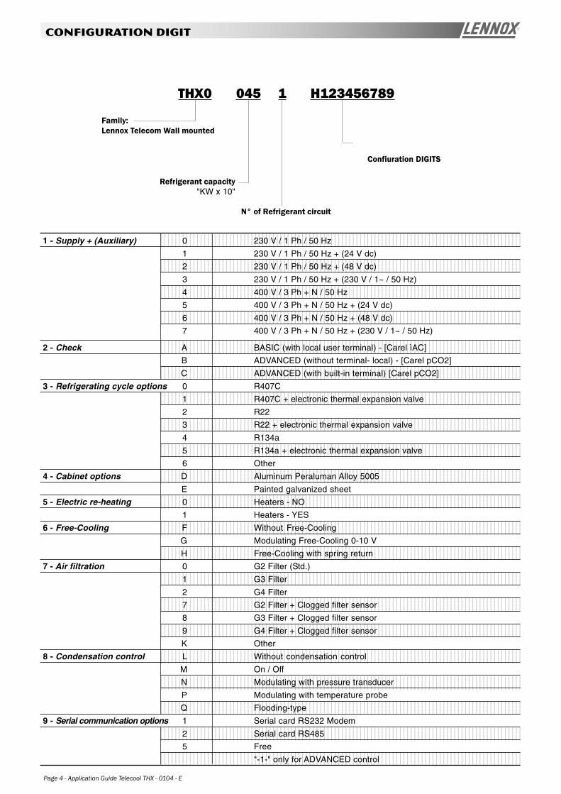
THX0 045 1 H123456789
Family:Lennox Telecom Wall mounted
Refrigerant capacity"KW x 10"
N° of Refrigerant circuit
1234567890123456789012345678901212345678901234567890123456789012123456789012345678901234567890121234123456789012345678901234567890121234567890123456789012345678901212345678901234567890123456789012123412345678901234567890123456789012123456789012345678901234567890121234567890123456789012345678901212341234567890123456789012345678901212345678901234567890123456789012123456789012345678901234567890121234
12345678901234567890123456789012123456789012345678901234567890121234567890123456789012345678901212341234567890123456789012345678901212345678901234567890123456789012123456789012345678901234567890121234123456789012345678901234567890121234567890123456789012345678901212345678901234567890123456789012123412345678901234567890123456789012123456789012345678901234567890121234567890123456789012345678901212341234567890123456789012345678901212345678901234567890123456789012123456789012345678901234567890121234
12345678901234567890123456789012123456789012345678901234567890121234567890123456789012345678901212341234567890123456789012345678901212345678901234567890123456789012123456789012345678901234567890121234123456789012345678901234567890121234567890123456789012345678901212345678901234567890123456789012123412345678901234567890123456789012123456789012345678901234567890121234567890123456789012345678901212341234567890123456789012345678901212345678901234567890123456789012123456789012345678901234567890121234
12345678901234567890123456789012123456789012345678901234567890121234567890123456789012345678901212341234567890123456789012345678901212345678901234567890123456789012123456789012345678901234567890121234123456789012345678901234567890121234567890123456789012345678901212345678901234567890123456789012123412345678901234567890123456789012123456789012345678901234567890121234567890123456789012345678901212341234567890123456789012345678901212345678901234567890123456789012123456789012345678901234567890121234
12345678901234567890123456789012123456789012345678901234567890121234567890123456789012345678901212341234567890123456789012345678901212345678901234567890123456789012123456789012345678901234567890121234123456789012345678901234567890121234567890123456789012345678901212345678901234567890123456789012123412345678901234567890123456789012123456789012345678901234567890121234567890123456789012345678901212341234567890123456789012345678901212345678901234567890123456789012123456789012345678901234567890121234
12345678901234567890123456789012123456789012345678901234567890121234567890123456789012345678901212341234567890123456789012345678901212345678901234567890123456789012123456789012345678901234567890121234123456789012345678901234567890121234567890123456789012345678901212345678901234567890123456789012123412345678901234567890123456789012123456789012345678901234567890121234567890123456789012345678901212341234567890123456789012345678901212345678901234567890123456789012123456789012345678901234567890121234
1234567890123456789012345678901212345678901234567890123456789012123456789012345678901234567890121234123456789012345678901234567890121234567890123456789012345678901212345678901234567890123456789012123412345678901234567890123456789012123456789012345678901234567890121234567890123456789012345678901212341234567890123456789012345678901212345678901234567890123456789012123456789012345678901234567890121234
1234567890123456789012345678901212345678901234567890123456789012123456789012345678901234567890121234123456789012345678901234567890121234567890123456789012345678901212345678901234567890123456789012123412345678901234567890123456789012123456789012345678901234567890121234567890123456789012345678901212341234567890123456789012345678901212345678901234567890123456789012123456789012345678901234567890121234
12345678901234567890123456789012123456789012345678901234567890121234567890123456789012345678901212341234567890123456789012345678901212345678901234567890123456789012123456789012345678901234567890121234123456789012345678901234567890121234567890123456789012345678901212345678901234567890123456789012123412345678901234567890123456789012123456789012345678901234567890121234567890123456789012345678901212341234567890123456789012345678901212345678901234567890123456789012123456789012345678901234567890121234
12345678901234567890123456789012123456789012345678901234567890121234567890123456789012345678901212341234567890123456789012345678901212345678901234567890123456789012123456789012345678901234567890121234123456789012345678901234567890121234567890123456789012345678901212345678901234567890123456789012123412345678901234567890123456789012123456789012345678901234567890121234567890123456789012345678901212341234567890123456789012345678901212345678901234567890123456789012123456789012345678901234567890121234
12345678901234567890123456789012123456789012345678901234567890121234567890123456789012345678901212341234567890123456789012345678901212345678901234567890123456789012123456789012345678901234567890121234123456789012345678901234567890121234567890123456789012345678901212345678901234567890123456789012123412345678901234567890123456789012123456789012345678901234567890121234567890123456789012345678901212341234567890123456789012345678901212345678901234567890123456789012123456789012345678901234567890121234
12345678901234567890123456789012123456789012345678901234567890121234567890123456789012345678901212341234567890123456789012345678901212345678901234567890123456789012123456789012345678901234567890121234123456789012345678901234567890121234567890123456789012345678901212345678901234567890123456789012123412345678901234567890123456789012123456789012345678901234567890121234567890123456789012345678901212341234567890123456789012345678901212345678901234567890123456789012123456789012345678901234567890121234
12345678901234567890123456789012123456789012345678901234567890121234567890123456789012345678901212341234567890123456789012345678901212345678901234567890123456789012123456789012345678901234567890121234123456789012345678901234567890121234567890123456789012345678901212345678901234567890123456789012123412345678901234567890123456789012123456789012345678901234567890121234567890123456789012345678901212341234567890123456789012345678901212345678901234567890123456789012123456789012345678901234567890121234
12345678901234567890123456789012123456789012345678901234567890121234567890123456789012345678901212341234567890123456789012345678901212345678901234567890123456789012123456789012345678901234567890121234123456789012345678901234567890121234567890123456789012345678901212345678901234567890123456789012123412345678901234567890123456789012123456789012345678901234567890121234567890123456789012345678901212341234567890123456789012345678901212345678901234567890123456789012123456789012345678901234567890121234
12345678901234567890123456789012123456789012345678901234567890121234567890123456789012345678901212341234567890123456789012345678901212345678901234567890123456789012123456789012345678901234567890121234123456789012345678901234567890121234567890123456789012345678901212345678901234567890123456789012123412345678901234567890123456789012123456789012345678901234567890121234567890123456789012345678901212341234567890123456789012345678901212345678901234567890123456789012123456789012345678901234567890121234
1234567890123456789012345678901212345678901234567890123456789012123456789012345678901234567890121234123456789012345678901234567890121234567890123456789012345678901212345678901234567890123456789012123412345678901234567890123456789012123456789012345678901234567890121234567890123456789012345678901212341234567890123456789012345678901212345678901234567890123456789012123456789012345678901234567890121234
1234567890123456789012345678901212345678901234567890123456789012123456789012345678901234567890121234123456789012345678901234567890121234567890123456789012345678901212345678901234567890123456789012123412345678901234567890123456789012123456789012345678901234567890121234567890123456789012345678901212341234567890123456789012345678901212345678901234567890123456789012123456789012345678901234567890121234
12345678901234567890123456789012123456789012345678901234567890121234567890123456789012345678901212341234567890123456789012345678901212345678901234567890123456789012123456789012345678901234567890121234123456789012345678901234567890121234567890123456789012345678901212345678901234567890123456789012123412345678901234567890123456789012123456789012345678901234567890121234567890123456789012345678901212341234567890123456789012345678901212345678901234567890123456789012123456789012345678901234567890121234
12345678901234567890123456789012123456789012345678901234567890121234567890123456789012345678901212341234567890123456789012345678901212345678901234567890123456789012123456789012345678901234567890121234123456789012345678901234567890121234567890123456789012345678901212345678901234567890123456789012123412345678901234567890123456789012123456789012345678901234567890121234567890123456789012345678901212341234567890123456789012345678901212345678901234567890123456789012123456789012345678901234567890121234
12345678901234567890123456789012123456789012345678901234567890121234567890123456789012345678901212341234567890123456789012345678901212345678901234567890123456789012123456789012345678901234567890121234123456789012345678901234567890121234567890123456789012345678901212345678901234567890123456789012123412345678901234567890123456789012123456789012345678901234567890121234567890123456789012345678901212341234567890123456789012345678901212345678901234567890123456789012123456789012345678901234567890121234
12345678901234567890123456789012123456789012345678901234567890121234567890123456789012345678901212341234567890123456789012345678901212345678901234567890123456789012123456789012345678901234567890121234123456789012345678901234567890121234567890123456789012345678901212345678901234567890123456789012123412345678901234567890123456789012123456789012345678901234567890121234567890123456789012345678901212341234567890123456789012345678901212345678901234567890123456789012123456789012345678901234567890121234
1 - Supply + (Auxiliary) 0 230 V / 1 Ph / 50 Hz
1 230 V / 1 Ph / 50 Hz + (24 V dc)
2 230 V / 1 Ph / 50 Hz + (48 V dc)
3 230 V / 1 Ph / 50 Hz + (230 V / 1~ / 50 Hz)
4 400 V / 3 Ph + N / 50 Hz
5 400 V / 3 Ph + N / 50 Hz + (24 V dc)
6 400 V / 3 Ph + N / 50 Hz + (48 V dc)
7 400 V / 3 Ph + N / 50 Hz + (230 V / 1~ / 50 Hz)
2 - Check A BASIC (with local user terminal) - [Carel ìAC]
B ADVANCED (without terminal- local) - [Carel pCO2]
C ADVANCED (with built-in terminal) [Carel pCO2]
3 - Refrigerating cycle options 0 R407C
1 R407C + electronic thermal expansion valve
2 R22
3 R22 + electronic thermal expansion valve
4 R134a
5 R134a + electronic thermal expansion valve
6 Other
4 - Cabinet options D Aluminum Peraluman Alloy 5005
E Painted galvanized sheet
5 - Electric re-heating 0 Heaters - NO
1 Heaters - YES
6 - Free-Cooling F Without Free-Cooling
G Modulating Free-Cooling 0-10 V
H Free-Cooling with spring return
7 - Air filtration 0 G2 Filter (Std.)
1 G3 Filter
2 G4 Filter
7 G2 Filter + Clogged filter sensor
8 G3 Filter + Clogged filter sensor
9 G4 Filter + Clogged filter sensor
K Other
8 - Condensation control L Without condensation control
M On / Off
N Modulating with pressure transducer
P Modulating with temperature probe
Q Flooding-type
9 - Serial communication options 1 Serial card RS232 Modem
2 Serial card RS485
5 Free
"-1-" only for ADVANCED control
Application Guide Telecool THX - 0104 - E Series - Page 5
manufacturing specifications
the ADVANCED microprocessor. Therefore, it is possible topilot directly the rotating speed suiting it to the differentoperating conditions, such as: de-humidification, energy saving,etc.
Finned pack evaporator
With its dimensions 25x21.65 and a 3/8. pipe it is composedof 0.10-mm thick aluminum fins and copper pipes expandedon the same for a complete contact. The design criteriaprivileges the front section with the advantage of reduced losseson the air side, while the exchange surface is sized so as toavoid de-humidification at the project rated conditions. Thecondensate collection tray can be accessed from the unit frontfor cleaning, and can be in galvanized sheet or, as option, inaustenitic stainless steel AISI 304L.
Recirculation air filtration
The filter is located upstream the evaporating coil and can beeasily extracted by removing the front panel dedicated to thefilter/damper section. Thanks to its position, it filters both therecirculation and the fresh air in case of Free-Cooling: in thelatter case, on the fresh air ejection section, a metalfilterprevents the nesting inside the container of small animalsor insects. The washable synthetic-type fiber filter, withefficiency EU2, is installed in a galvanized sheet frame for aneasy maintenance.
Condensing section fanThe axial-type used fans, with wing-shaped blades, are featuredby a high covering degree. All used 6-pole motors limit thesound emissions, and are outer rotor type to improve the energyefficiency and reduce the magnetic noise when they areadjusted with phase disconnecting devices (optional).
Condenser with finned packWith dimensions 25x21.65 and a 3/8. pipe it is composed of0.10-mm thick aluminum fins and copper pipes expanded onthe same for a complete contact. The design criteria privilegesthe front section with the advantage of reduced losses on theair side, so that it is possible to use 6-pole fans with minimizedemitted sound power. The condensing coil can be equippedwith a metal filter that can be easily removed fromone ofthemachine sides: this double access enables the maintenanceeven in case of double installation on the container wall.
Electric board
It is located in a separate cabinet hidden on the back side bythe recirculation air before it is cooled by the evaporating coil: this aspect is extremely important for both the componentcooling and, at the same time, for preventing the condensa-tion on the bottom side of the board. All on-board systemscomply with the EEC Directive "Low tension 73/23" and withthe related norms. The access to the electric board is possiblewith operating unit as it is completely separated from the airflow; the protection degree with open panel is IP20.
Manufacturing specifications
Structure
The THX series units are dedicated to the outdoor use withtemperatures ranging between .20°C (under condensationcontrol) and +45°C. The entire inner structure is made up ofhot electro-galvanized sheet with high thickness, and the outerpaneling is in smooth 5005 aluminum alloy or, upon request, ingalvanized sheet painted with epoxy-polyester powders RAL9002, oven-cured at 180°C. If painted, the colour of the unitsdepends on the customer.s specifications for re-order batchesof more than 20 pieces. The innovative global design of themachine enables a complete front accessibility whereas theoutstanding possibility of extracting/fitting thedamper fromthefront offers the double chance of upgrading on site of the ma-chines originally without the Free-Cooling option, and it offersthe accessibility to the evaporating coil and to the condensatecollection tray, too.
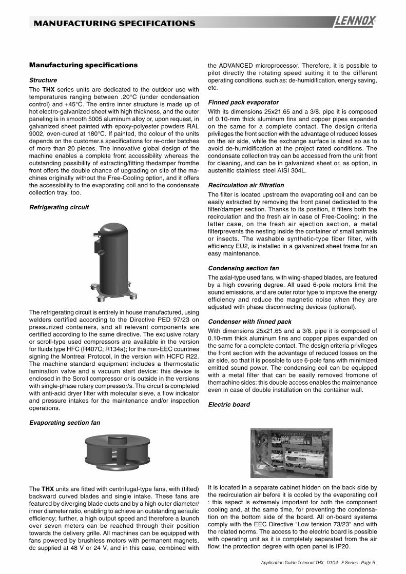
Refrigerating circuit
The refrigerating circuit is entirely in house manufactured, usingwelders certified according to the Directive PED 97/23 onpressurized containers, and all relevant components arecertified according to the same directive. The exclusive rotaryor scroll-type used compressors are available in the versionfor fluids type HFC (R407C; R134a); for the non-EEC countriessigning the Montreal Protocol, in the version with HCFC R22.The machine standard equipment includes a thermostaticlamination valve and a vacuum start device: this device isenclosed in the Scroll compressor or is outside in the versionswith single-phase rotary compressor/s. The circuit is completedwith anti-acid dryer filter with molecular sieve, a flow indicatorand pressure intakes for the maintenance and/or inspectionoperations.
Evaporating section fan
The THX units are fitted with centrifugal-type fans, with (tilted)backward curved blades and single intake. These fans arefeatured by diverging blade ducts and by a high outer diameter/inner diameter ratio, enabling to achieve an outstanding aeraulicefficiency; further, a high output speed and therefore a launchover seven meters can be reached through their positiontowards the delivery grille. All machines can be equipped withfans powered by brushless motors with permanent magnets,dc supplied at 48 V or 24 V, and in this case, combined with
Page 6 - Application Guide Telecool THX - 0104 - E
manufacturing specifications
PackingThe THX units are packed on wooden pallet with anti-shockcardboard anglesand upper protection in cardboard/polystyrene. In the end, thewhole packing is wrapped with protection transparent polythenefilm.
InterconnectivityAll units can be connected with remote supervision systemsby the use of .Gateway.. When using the .mP. control of the.ADVANCED. type, there is the possibility of piloting directly aGSM modem able to send and receive SMS messages.
Application field
The machines have been designed to operate with outdoortemperatures "oT" up to +45°C and indoor temperatures "iT"ranging between 18°C - R.H. 40% and 35°C - R.H. 50%. Forthe applications with low outdoor temperature, the condensa-tion control is required:
- Absent for oT > 20°C
- Modulating for -20°C < oT < 20°C
- Flooding -35°C < oT < -20°C
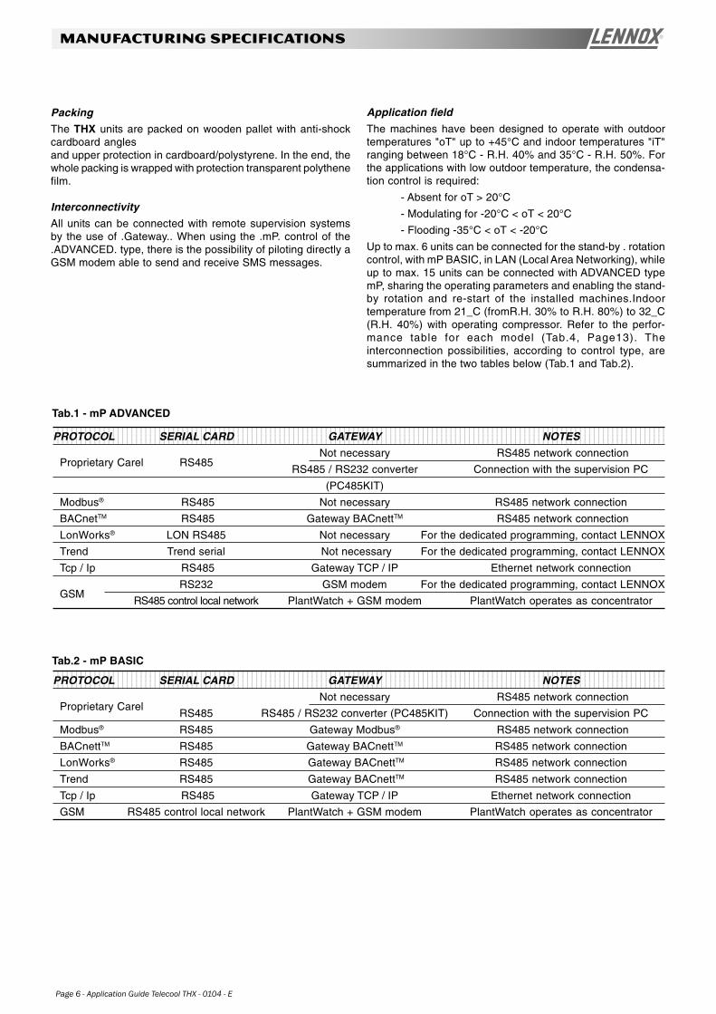
Up to max. 6 units can be connected for the stand-by . rotationcontrol, with mP BASIC, in LAN (Local Area Networking), whileup to max. 15 units can be connected with ADVANCED typemP, sharing the operating parameters and enabling the stand-by rotation and re-start of the installed machines.Indoortemperature from 21_C (fromR.H. 30% to R.H. 80%) to 32_C(R.H. 40%) with operating compressor. Refer to the perfor-mance table for each model (Tab.4, Page13). Theinterconnection possibilities, according to control type, aresummarized in the two tables below (Tab.1 and Tab.2).
1234567890123456789012345678901212345678901234567890123456789012123456789012345678901234567890121234567890123456789012345678901212345612345678901234567890123456789012123456789012345678901234567890121234567890123456789012345678901212345678901234567890123456789012123456123456789012345678901234567890121234567890123456789012345678901212345678901234567890123456789012123456789012345678901234567890121234561234567890123456789012345678901212345678901234567890123456789012123456789012345678901234567890121234567890123456789012345678901212345612345678901234567890123456789012123456789012345678901234567890121234567890123456789012345678901212345678901234567890123456789012123456PROTOCOL SERIAL CARD GATEWAY NOTES
Not necessary RS485 network connectionProprietary Carel
RS485 RS485 / RS232 converter (PC485KIT) Connection with the supervision PC
Modbus® RS485 Gateway Modbus® RS485 network connection
BACnettTM RS485 Gateway BACnettTM RS485 network connection
LonWorks® RS485 Gateway BACnettTM RS485 network connection
Trend RS485 Gateway BACnettTM RS485 network connection
Tcp / Ip RS485 Gateway TCP / IP Ethernet network connection
GSM RS485 control local network PlantWatch + GSM modem PlantWatch operates as concentrator
Tab.2 - mP BASIC
12345678901234567890123456789012123456789012345678901234567890121234567890123456789012345678901212345678901234567890123456789012123456123456789012345678901234567890121234567890123456789012345678901212345678901234567890123456789012123456789012345678901234567890121234561234567890123456789012345678901212345678901234567890123456789012123456789012345678901234567890121234567890123456789012345678901212345612345678901234567890123456789012123456789012345678901234567890121234567890123456789012345678901212345678901234567890123456789012123456PROTOCOL SERIAL CARD GATEWAY NOTES
Not necessary RS485 network connectionProprietary Carel RS485
RS485 / RS232 converter Connection with the supervision PC
(PC485KIT)
Modbus® RS485 Not necessary RS485 network connection
BACnetTM RS485 Gateway BACnettTM RS485 network connection
LonWorks® LON RS485 Not necessary For the dedicated programming, contact LENNOX
Trend Trend serial Not necessary For the dedicated programming, contact LENNOX
Tcp / Ip RS485 Gateway TCP / IP Ethernet network connection
RS232 GSM modem For the dedicated programming, contact LENNOXGSM
RS485 control local network PlantWatch + GSM modem PlantWatch operates as concentrator
Tab.1 - mP ADVANCED
Application Guide Telecool THX - 0104 - E Series - Page 7
manufacturing specifications
12345678901234567890123456789012123456789012345678901234561234567890123456789012345678901212345678901234567890123456123456789012345678901234567890121234567890123456789012345612345678901234567890123456789012123456789012345678901234561234567890123456789012345678901212345678901234567890123456
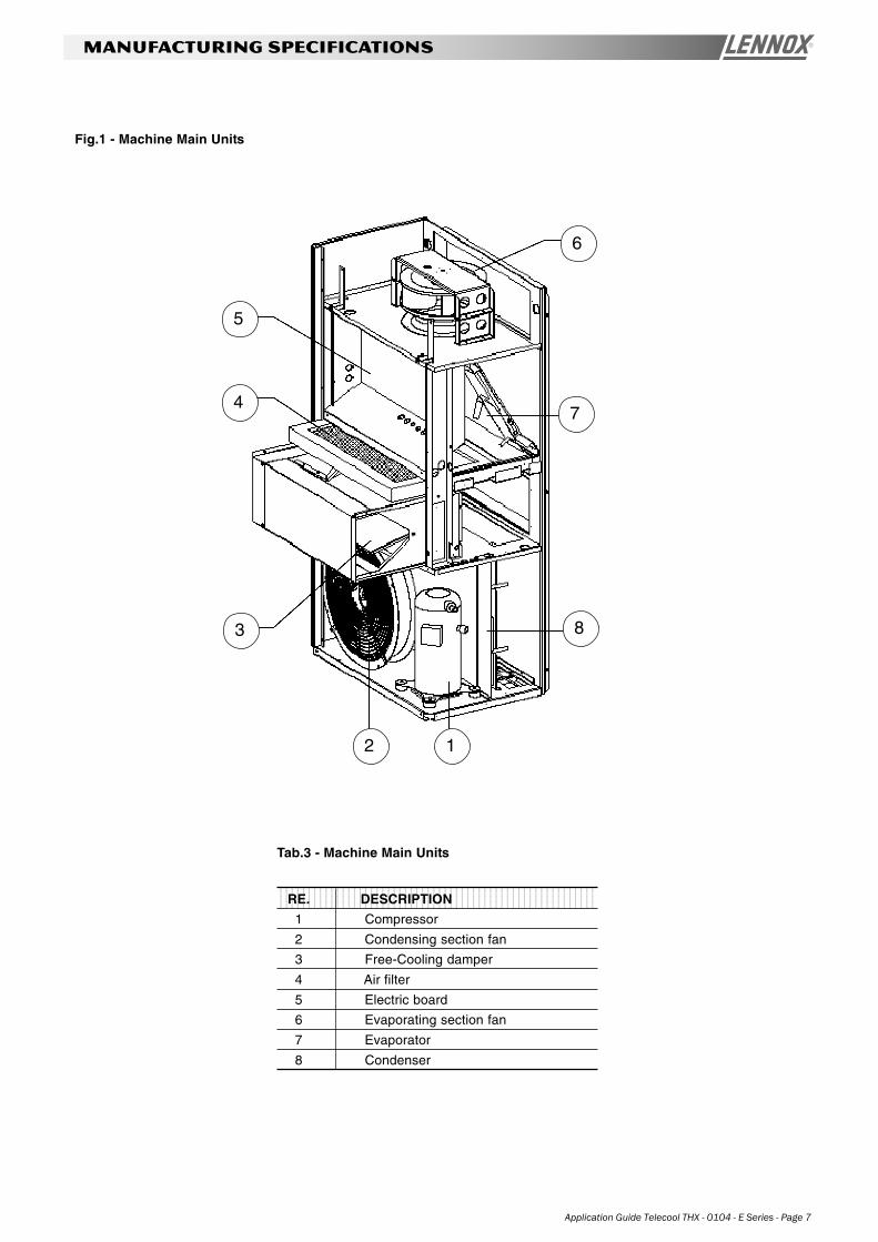
Tab.3 - Machine Main Units
RE. DESCRIPTION
1 Compressor
2 Condensing section fan
3 Free-Cooling damper
4 Air filter
5 Electric board
6 Evaporating section fan
7 Evaporator
8 Condenser
Fig.1 - Machine Main Units
1234567123456712345671234567123456712345671234567
11234567123456712345671234567123456712345671234567
2
12345671234567123456712345671234567123456712345671234567
3
12345671234567123456712345671234567123456712345671234567
4
1234567123456712345671234567123456712345671234567
5
1234567812345678123456781234567812345678123456781234567812345678
6
12345671234567123456712345671234567123456712345671234567
7
1234567123456712345671234567123456712345671234567
8
Page 8 - Application Guide Telecool THX - 0104 - E
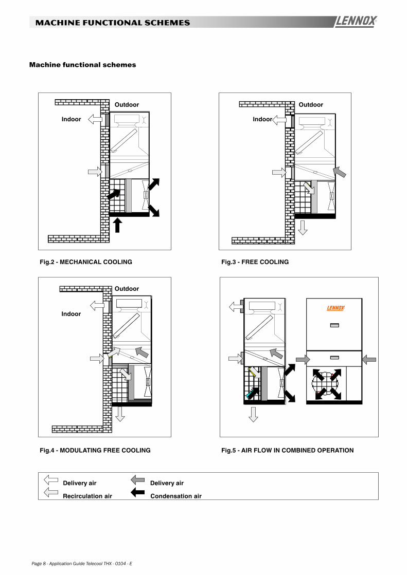
MACHINE FUNCTIONAL SCHEMES
Machine functional schemes
Fig.2 - MECHANICAL COOLING Fig.3 - FREE COOLING
Fig.4 - MODULATING FREE COOLING Fig.5 - AIR FLOW IN COMBINED OPERATION
Delivery air
Recirculation air
Delivery air
Condensation air
Indoor
Outdoor
Indoor
Indoor
Outdoor
Outdoor
Application Guide Telecool THX - 0104 - E Series - Page 9
control software and hardware
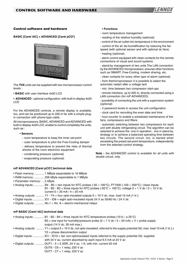
Control software and hardware
BASIC [Carel ìAC] + ADVANCED [Carel pCO2]
The THX units can be supplied with two microprocessor controllevels :
• BASIC with user interface 4x20 LCD
• ADVANCED : optional configuration: with built-in display 4x20LCD
For the ADVANCED controls, a remote display is available,too, and can be positioned up to 200 m far with a simple plug-in connection with phone-type cable.
All microprocessors, BASIC, ADVANCED and ADVANCED withbuilt-in display 4x20 LCD, enable to control completely the units,such as :
• Sensors
- room temperature to keep the inner set-point
- outer temperature to pilot the Free-Cooling damper
- delivery temperature to prevent the risks of thermalshocks of the room electronic equipment
- condensing pressure (optional)
- evaporating pressure (optional)
• Functions
- room temperature management
- reading of the relative humidity (optional)
- control of the air outlet min.temperature in the environment
- control of the air de-humidification by reducing the fanspeed (with optional sensor and with optional dc fans)
- heating (optional)
- alarm control equipped with clean contacts for the remoteconnections of visual and sound systems
- stand-by management of two units.The LAN connectionby the ADVANCED microprocessor, ensures other functionssuch as SMART, Free-Cooling, modem sharing, etc.
- clean contacts for every other type of alarm (optional)
- from themicroprocessor it is possible to select theautomatic restart after a voltage lack
- min. time between two compressor start-ups
- remote interface, up to 200 m, directly connected using aLAN connection (for mP ADVANCED)
- possibility of connecting the unit with a supervision system(optional)
- 2 password levels to access the unit configuration
- clock card for recording the even date and time
- hour-counter to enable a scheduled maintenance of thefans, compressors and filters
- automatic switching between two compressors for eachunit with double refrigerating circuit. The algorithm can beselected to achieve the .one in operation . one in stand by.strategy or to achieve a balanced operating time betweentwo circuits. The second circuit, too, is started whenexceeding the preset set-point temperature, independentlyfrom the selected control strategy.
Note : the ADVANCED control is available for all units withdouble circuit, only.
mP ADVANCED [Carel pCO2] technical data
• Flash memory: ............ 1 MByte expandable to 16 MByte• RAM memory: ............. 256 kByte expandable to 1 MByte• Parameter memory: ... 2 kByte• Analog inputs: ............. B4 - B5 = two inputs for NTC probes (-50 ÷ 100°C), PT1000 (-100 ÷ 200°C) / clean inputs
B1 - B2 - B3 = three inputs for NTC probes (-50°C ÷ 100°C); voltage 0 ÷ 1 V dc / 0 ÷ 10 V dccurrent 0 ÷ 20 mA / 4 ÷ 20 mA
• Analog outputs: .......... Y1 - Y4 = four opto-insulated outputs 0 ÷ 10 V dc, max. load 10 mA (1 k )• Digital inputs: .............. ID1 - ID8 = eight opto-insulated inputs 24 V ac 50/60 Hz / 24 V dc• Digital outputs: ........... No.1 ÷ No. 8 = electro-mechanical relays
mP BASIC [Carel ìAC] technical data
• Analog inputs: ............. B1 - B2 - B4 = three inputs for NTC temperature probes (10 k . a 25°C)B3 = one input for humidity/pressure probe (0 ÷ 1 V dc / 4 ÷ 20 mA) + V = probe supplyoutput (14 V dc, 30 mA max.)
• Analog outputs: .......... Y1 = output 0 ÷ 10 V dc, not opto-insulated, referred to the supply potential G0, max. load 10 mA (1 k ).)Y2 = phase disconnection output
• Digital inputs: .............. ID1 - ID10 = ten non-optoinsulated inputs referred to the supply potential G0, suppliedwith 24 V ac, current absorbed by each input 6.5 mA at 24 V ac
• Digital outputs: ........... OUT1 - 5 = 5 SSR, 24 V ac, 1 A, with min. current 20 mAOUT6 - C6 = 1 relay, 220 V acOUT7 - C7 = 1 relay, 220 V ac
Page 10 - Application Guide Telecool THX - 0104 - E
LIST OF MAIN OPTIONS
1 - ADVANCED microprocessor
Programmablemicroprocessor with 16bit and high performan-ces.
2 - Air differential pressure switch
3 - Double supply
• AC main supply from the mains:
- compressor/s
- fan/s of the condensing section
- heating
• Auxiliary supply 48 V dc (24 V dc, upon request):
- microprocessor
- evaporating section fan
- damper servomotor
Note : it is possible to activate the fan speed control to enablethe coil energy saving during its operation.
SFT® "Side Free-Cooling Technology"
The innovative Free-Cooling system enables to reachoutstanding efficiency levels, above all when operatingsimultaneously with the mechanical cooling: this situation, inmany central European climate areas, represents over 50% ofthe yearly total hours.
4 - Refrigerant R134a
For extreme outdoor conditions up to +55°C.
5 - Free-Cooling with damperThanks to the unit designing principle, it is possible to carryout the .upgrading on site. on the units not equipped with theFree-Cooling option
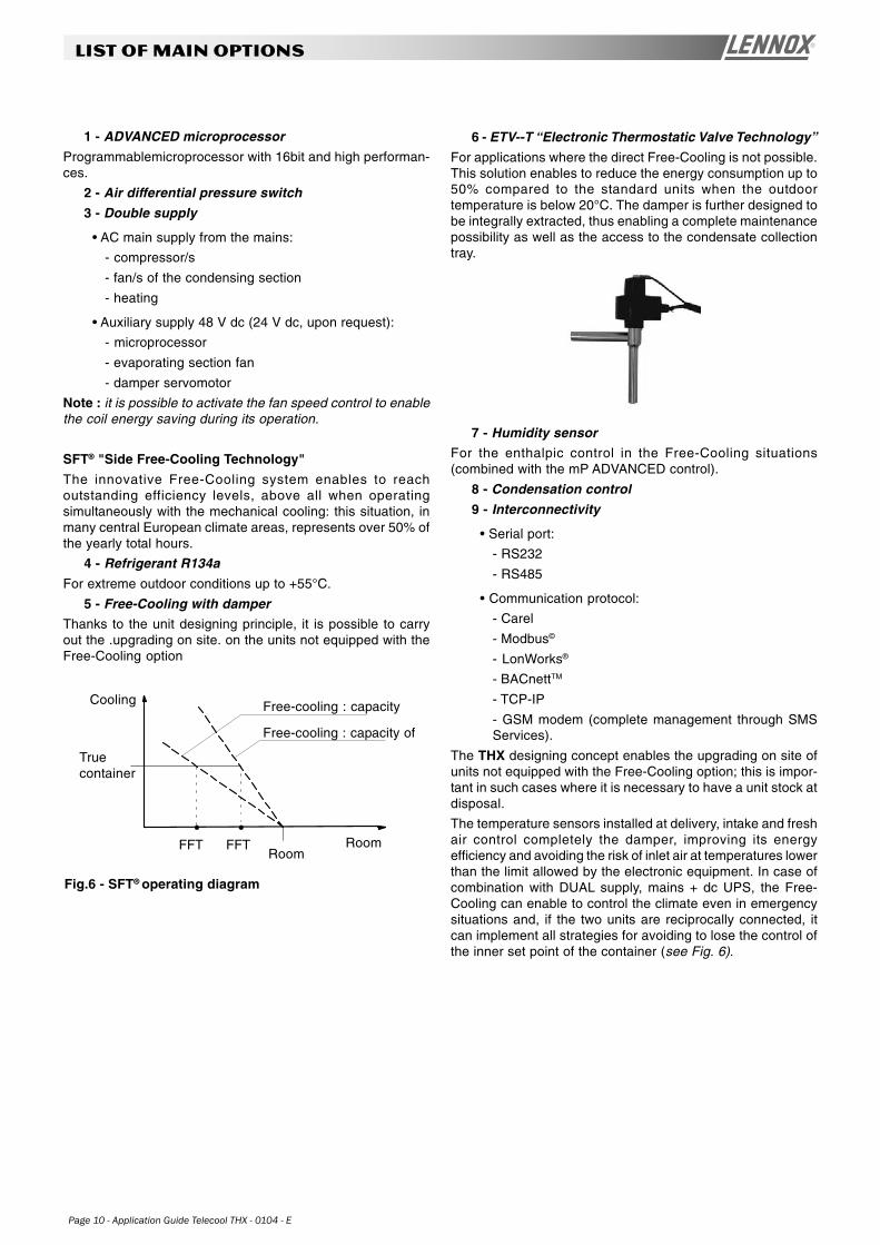
6 - ETV--T “Electronic Thermostatic Valve Technology”
For applications where the direct Free-Cooling is not possible.This solution enables to reduce the energy consumption up to50% compared to the standard units when the outdoortemperature is below 20°C. The damper is further designed tobe integrally extracted, thus enabling a complete maintenancepossibility as well as the access to the condensate collectiontray.
7 - Humidity sensorFor the enthalpic control in the Free-Cooling situations(combined with the mP ADVANCED control).
8 - Condensation control
9 - Interconnectivity
• Serial port:
- RS232
- RS485
• Communication protocol:
- Carel
- Modbus©
- LonWorks®
- BACnettTM
- TCP-IP
- GSM modem (complete management through SMSServices).
The THX designing concept enables the upgrading on site ofunits not equipped with the Free-Cooling option; this is impor-tant in such cases where it is necessary to have a unit stock atdisposal.
The temperature sensors installed at delivery, intake and freshair control completely the damper, improving its energyefficiency and avoiding the risk of inlet air at temperatures lowerthan the limit allowed by the electronic equipment. In case ofcombination with DUAL supply, mains + dc UPS, the Free-Cooling can enable to control the climate even in emergencysituations and, if the two units are reciprocally connected, itcan implement all strategies for avoiding to lose the control ofthe inner set point of the container (see Fig. 6).
Fig.6 - SFT® operating diagram
Cooling
Truecontainer
Free-cooling : capacity
Free-cooling : capacity of
RoomRoomFFT FFT
Application Guide Telecool THX - 0104 - E Series - Page 11
lIST OF MAIN OPTIONS
Damper servomotor with spring return
It positions the dampers completely open or completely closedat the customer's choice in case of power lack: with an operationsignal connected with a fire alarm, the damper is usuallypositioned closed, to enable the operation of the automaticswitching-off systems. This option must be defined at the order.
Clogged filter sensor
This differential pressure sensor detects the filter clogging andgenerates an alarm displayed by the microprocessor control.
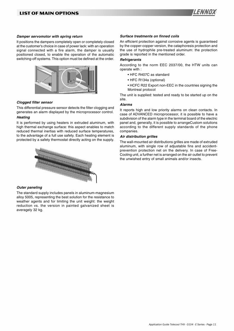
Heating
It is performed by using heaters in extruded aluminum, withhigh thermal exchange surface: this aspect enables to matchreduced thermal inertias with reduced surface temperatures,to the advantage of a full use safety. Each heating element isprotected by a safety thermostat directly acting on the supply.
Outer paneling
The standard supply includes panels in aluminum-magnesiumalloy 5005, representing the best solution for the resistance toweather agents and for limiting the unit weight: the weightreduction vs. the version in painted galvanized sheet isaveragely 32 kg.
Surface treatments on finned coilsAn efficient protection against corrosive agents is guaranteedby the copper-copper version, the cataphoresis protection andthe use of hydrophile pre-treated aluminum: the protectiongrade is reported in the mentioned order.
RefrigerantsAccording to the norm EEC 2037/00, the HTW units canoperate with :
• HFC R407C as standard
• HFC R134a (optional)
• HCFC R22 Export non-EEC in the countries signing theMontreal protocol
The unit is supplied: tested and ready to be started up on thesite.
Alarms
It reports high and low priority alarms on clean contacts. Incase of ADVANCED microprocessor, it is possible to have asubdivision of the alarm type in the terminal board of the electricpanel and, generally, it is possible to arrangeCustom solutionsaccording to the different supply standards of the phonecompanies.
Air distribution grilles
The wall-mounted air distributions grilles are made of extrudedaluminum, with single row of adjustable fins and accident-prevention protection net on the delivery. In case of Free-Cooling unit, a further net is arranged on the air outlet to preventthe unwished entry of small animals and/or insects.
Page 12 - Application Guide Telecool THX - 0104 - E
Data according to Eurovent standard conditions XXXPT Total cooling / heating capacity in kW PS Sensible cooling capacity in kW PA Compressor absorbed power
Tests and references standards
Tests and Reference StandardsSafety
The THX units have been designed, manufactured and testedaccording to the directives of the European Union :
• 98/37/EC (former 89/392/EEC, 91/368/EEC, 93/68/EEC)
• 89/336/EEC
• 73/23/EEC
Electric boards
The electric boards comply with
EN 60204-1.
Electro--magnetic compatibility
The THX unit complies with the following EMC standards:
• EN 50081-1, Emissions (.Generic emission standard,Part 1: residential, commercial and light industrial.,January 1992)
• EN 50082-2, Electro-magnetic compatibility (.Genericemission standard, Part 2: industrial environment., March1995)
Conformity
Each THX unit is supplied complete with test certificate andconformity certificate according to the Directives of theEuropean Union.The units are .CE. marked.
Application Guide Telecool THX - 0104 - E Series - Page 13
technical data
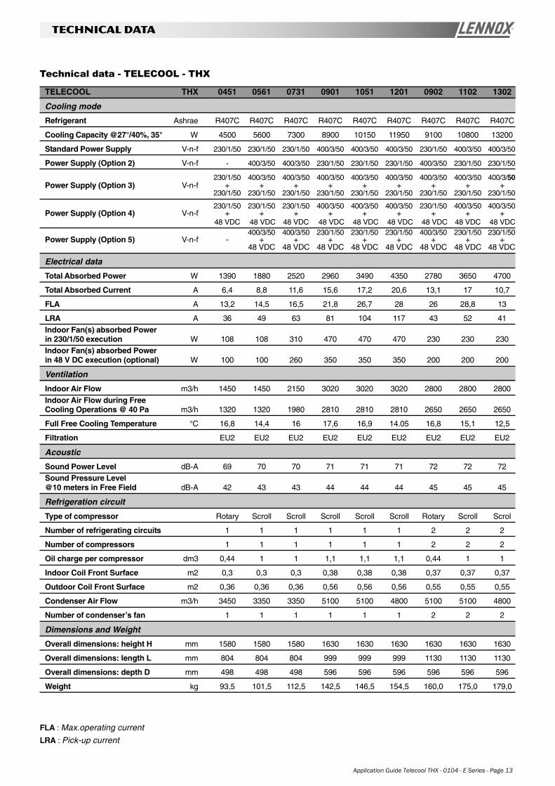
TELECOOL THX 0451 0561 0731 0901 1051 1201 0902 1102 1302
Cooling mode
Refrigerant Ashrae R407C R407C R407C R407C R407C R407C R407C R407C R407C
Cooling Capacity @27°/40%, 35° W 4500 5600 7300 8900 10150 11950 9100 10800 13200
Standard Power Supply V-n-f 230/1/50 230/1/50 230/1/50 400/3/50 400/3/50 400/3/50 230/1/50 400/3/50 400/3/50
Power Supply (Option 2) V-n-f - 400/3/50 400/3/50 230/1/50 230/1/50 230/1/50 400/3/50 230/1/50 230/1/50
230/1/50 400/3/50 400/3/50 400/3/50 400/3/50 400/3/50 400/3/50 400/3/50 400/3/50Power Supply (Option 3) V-n-f + + + + + + + + +
230/1/50 230/1/50 230/1/50 230/1/50 230/1/50 230/1/50 230/1/50 230/1/50 230/1/50
230/1/50 230/1/50 230/1/50 400/3/50 400/3/50 400/3/50 230/1/50 400/3/50 400/3/50Power Supply (Option 4) V-n-f + + + + + + + + +
48 VDC 48 VDC 48 VDC 48 VDC 48 VDC 48 VDC 48 VDC 48 VDC 48 VDC400/3/50 400/3/50 230/1/50 230/1/50 230/1/50 400/3/50 230/1/50 230/1/50
Power Supply (Option 5) V-n-f - + + + + + + + +48 VDC 48 VDC 48 VDC 48 VDC 48 VDC 48 VDC 48 VDC 48 VDC
Electrical data
Total Absorbed Power W 1390 1880 2520 2960 3490 4350 2780 3650 4700
Total Absorbed Current A 6,4 8,8 11,6 15,6 17,2 20,6 13,1 17 10,7
FLA A 13,2 14,5 16,5 21,8 26,7 28 26 28,8 13
LRA A 36 49 63 81 104 117 43 52 41
Indoor Fan(s) absorbed Powerin 230/1/50 execution W 108 108 310 470 470 470 230 230 230Indoor Fan(s) absorbed Powerin 48 V DC execution (optional) W 100 100 260 350 350 350 200 200 200
Ventilation
Indoor Air Flow m3/h 1450 1450 2150 3020 3020 3020 2800 2800 2800
Indoor Air Flow during FreeCooling Operations @ 40 Pa m3/h 1320 1320 1980 2810 2810 2810 2650 2650 2650
Full Free Cooling Temperature °C 16,8 14,4 16 17,6 16,9 14.05 16,8 15,1 12,5
Filtration EU2 EU2 EU2 EU2 EU2 EU2 EU2 EU2 EU2
Acoustic
Sound Power Level dB-A 69 70 70 71 71 71 72 72 72Sound Pressure Level@10 meters in Free Field dB-A 42 43 43 44 44 44 45 45 45
Refrigeration circuit
Type of compressor Rotary Scroll Scroll Scroll Scroll Scroll Rotary Scroll Scrol
Number of refrigerating circuits 1 1 1 1 1 1 2 2 2
Number of compressors 1 1 1 1 1 1 2 2 2
Oil charge per compressor dm3 0,44 1 1 1,1 1,1 1,1 0,44 1 1
Indoor Coil Front Surface m2 0,3 0,3 0,3 0,38 0,38 0,38 0,37 0,37 0,37
Outdoor Coil Front Surface m2 0,36 0,36 0,36 0,56 0,56 0,56 0,55 0,55 0,55
Condenser Air Flow m3/h 3450 3350 3350 5100 5100 4800 5100 5100 4800
Number of condenser’s fan 1 1 1 1 1 1 2 2 2
Dimensions and Weight
Overall dimensions: height H mm 1580 1580 1580 1630 1630 1630 1630 1630 1630
Overall dimensions: length L mm 804 804 804 999 999 999 1130 1130 1130
Overall dimensions: depth D mm 498 498 498 596 596 596 596 596 596
Weight kg 93,5 101,5 112,5 142,5 146,5 154,5 160,0 175,0 179,0
Technical data - TELECOOL - THX
FLA : Max.operating current
LRA : Pick-up current
Page 14 - Application Guide Telecool THX - 0104 - E
dimensional drawings
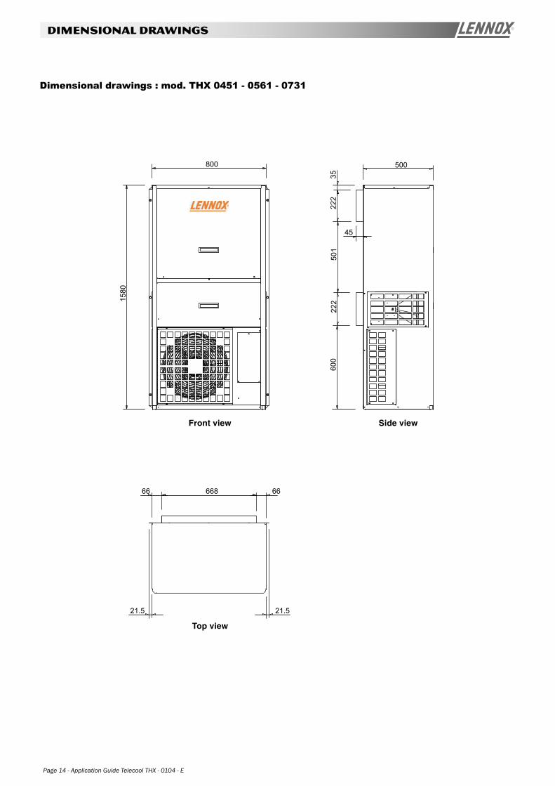
1580
800 500
3522
250
122
260
0
66866 66
21.521.5
45
Dimensional drawings : mod. THX 0451 - 0561 - 0731
Side viewFront view
Top view
Application Guide Telecool THX - 0104 - E Series - Page 15
dimensional drawings
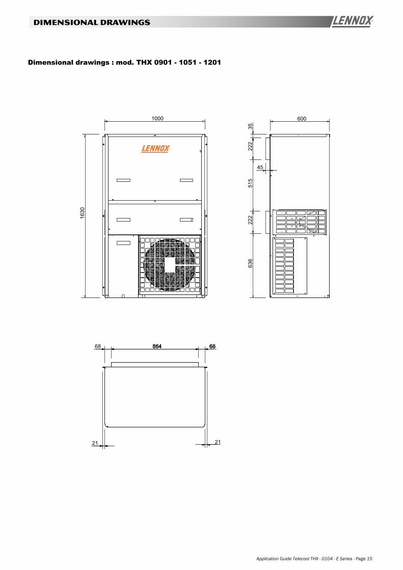
Dimensional drawings : mod. THX 0901 - 1051 - 1201
1000
1630
2121
864 6868
600
3522
251
522
263
6
864 68864 68
45
Page 16 - Application Guide Telecool THX - 0104 - E
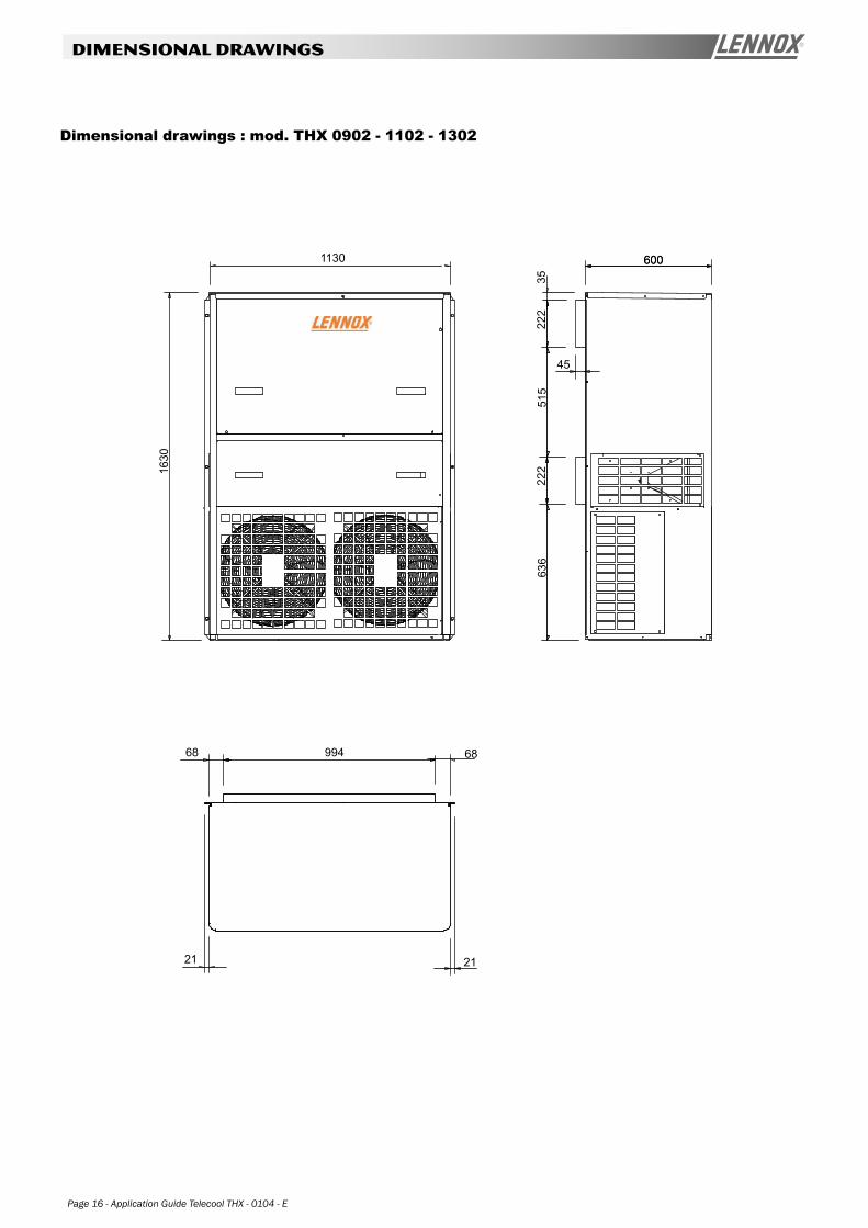
dimensional drawings
Dimensional drawings : mod. THX 0902 - 1102 - 1302
68
600600
222
222
636
1630
21
3551
5
21
1130
99468
45
www.lennoxeurope.com
www.lennoxbelgium.com
www.lennox.cz
www.lennoxfrance.com
www.lennoxdeutschland.com
www.lennoxuk.com
www.lennoxireland.com
www.lennoxnederland.com
www.lennoxpolska.com
www.lennoxportugal.com
www.lennoxrussia.com
www.lennoxdistribution.com
www.lennoxspain.com
www.lennoxrussia.com
www.lennoxdistribution.com
TELECOOL THX-AGU-0104-E
BELGIUM, LUXEMBOURG
CZECH REPUBLIC
FRANCE
GERMANY
GREAT BRITAIN
IRELAND
NETHERLANDS
POLAND
PORTUGAL
RUSSIA
SLOVAKIA
SPAIN
UKRAINE
OTHER COUNTRIES
Due to Lennox’s ongoing commitment to quality,
the Specifications, Ratings and Dimensions are
subject to change without notice and without
incurring liability.
Improper installation, adjustment, alteration,
service or maintenance can cause property
damage or personal injury.
Installation and service must be performed by a
qualified installer and servicing agency.