Application Guide for Manual Material-Handling ......7 NIOSH EQUATION 1991 The 1991 NIOSH equation...
36
Application Guide for Manual Material-Handling Requirements in SEMI S8 International SEMATECH Manufacturing Initiative Technology Transfer #09095029A-ENG
Transcript of Application Guide for Manual Material-Handling ......7 NIOSH EQUATION 1991 The 1991 NIOSH equation...

Application Guide for Manual Material-Handling Requirements in SEMI S8
International SEMATECH Manufacturing Initiative Technology Transfer #09095029A-ENG

© 2010 International SEMATECH Manufacturing Initiative, Inc.
Advanced Materials Research Center, AMRC, International SEMATECH Manufacturing Initiative, and ISMI are servicemarks of SEMATECH, Inc. SEMATECH and the SEMATECH logo are registered servicemarks
of SEMATECH, Inc. All other servicemarks and trademarks are the property of their respective owners.

Application Guide for Manual Material-Handling Requirements in SEMI S8
Technology Transfer #09095029A-ENG International SEMATECH Manufacturing Initiative
December 7, 20009
Abstract: This document describes the correct use of methods to assess manual material-handling (MMH) tasks to determine their compliance with SEMI S8, Safety Guidelines for Ergonomics Engineering of Semiconductor Manufacturing Equipment. The three commonly accepted methods addressed are the 1991 NIOSH equation, 3D biomechanical analysis, and psychophysical assessment.
Keywords: Ergonomics, Employee Safety, Standards Conformance, Safety Standards
Authors: Ed Guild, Mark Harralson, Daryl Meekins, William Petry, Paul Schwab, and Stephen Werner
Approvals: James Beasley, Project Manager Ron Remke, Program Manager Joe Draina, Director Laurie Modrey, Technology Transfer Team Leader


iii
ISMI Technology Transfer #09095029A-ENG
Table of Contents
1 EXECUTIVE SUMMARY .....................................................................................................1
2 TERMINOLOGY....................................................................................................................1
3 REFERENCED STANDARDS...............................................................................................1
4 REQUIRED DOCUMENTATION – TASK DESCRIPTION.................................................2
5 REQUIRED DOCUMENTATION – TASK ASSESSMENT .................................................2
6 ANALYSIS TOOL SELECTION............................................................................................4
7 NIOSH EQUATION 1991.......................................................................................................5
8 BIOMECHANICAL MODELS: UNIVERSITY OF MICHIGAN 3D STATIC STRENGTH PREDICTION PROGRAM (3DSSPP) .............................................................9
9 PSYCHOPHYSICAL CAPACITY DATA 10
10 PSYCHOPHYSICAL CAPACITY DATA 17
11 PSYCHOPHYSICAL CAPACITY DATA – TWO-HAND PULL DATA............................19
12 PSYCHOPHYSICAL CAPACITY DATA – TWO-HAND PUSH DATA............................21
13 PSYCHOPHYSICAL CAPACITY DATA 24
14 PSYCHOPHYSICAL CAPACITY DATA – KNEELING TASKS.......................................24
15 PSYCHOPHYSICAL CAPACITY DATA – SEATED TASKS............................................27
16 PSYCHOPHYSICAL CAPACITY DATA – LYING TASKS...............................................27
– TWO–HANDED LIFT/LOWER DATA ........
– ONE-HAND LIFT DATA..............................
– ONE-HAND PUSH/PULL FORCES.............

iv
Technology Transfer #09095029A-ENG ISMI
List of Figures
Figure 1 NIOSH (1991) Equation Variables H, V, and D.........................................................5
Figure 2 Determining Angle of Asymmetry (A) for NIOSH Lifting Equation ........................6
Figure 3 3DSSPP Output Screens...........................................................................................10
Figure 4 Description of Container Orientations (Flat, Vertical, Deep) ..................................26
List of Tables
Table 1 Criteria to Determine Appropriate MMH Analysis Tool(s) .......................................4
Table 2 NIOSH 1991 Equation Multipliers ............................................................................5
Table 3 Estimates for Horizontal Reach..................................................................................5
Table 4 Frequency Multiplier (FM) Table...............................................................................7
Table 5 Coupling Multiplier....................................................................................................7
Table 6 Hand-to-Container Coupling Classification...............................................................8
Table 7 Description of Handle Design Classifications ...........................................................8
Table 8 Description of the 3DSSPP Variables.......................................................................10
Table 9 Recommended Weight of Lift (kg) for Two-Handed Symmetrical Lifting for an 8-hour Shift..........................................................................................................12
Table 10 Recommended Weight of Lift (lbs) for Two-Handed Symmetrical Lifting for an 8-hour Shift ....................................................................................................14
Table 11 Multipliers for Psychophysical Data ........................................................................16
Table 12 One-Hand Lift Data Infrequent Lifts (F < 1 lift per minute) ...................................18
Table 13 One-Hand Lift Data Frequent Lifts (F > 1 lift per minute) ......................................18
Table 14 Maximum Acceptable Two-Hand Pull Forces, Initial (Sustained) Forces ...............20
Table 15 Maximum Acceptable Two-Hand Push Forces Initial (Sustained) Forces...............22
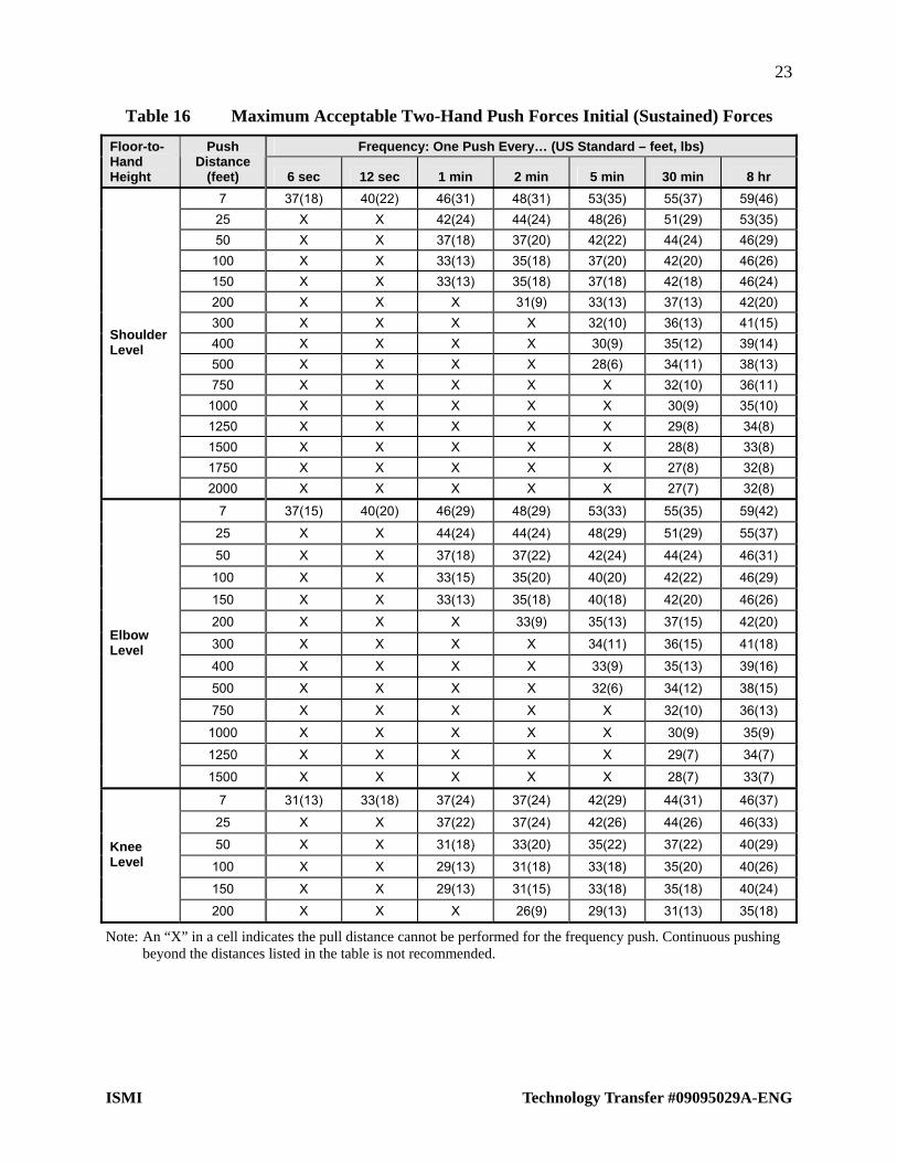
Table 16 Maximum Acceptable Two-Hand Push Forces Initial (Sustained) Forces...............23
Table 17 Recommended Weight Limit (RWL) for Kneeling Tasks ........................................25
Table 18 Recommended Weight of Lifts for Sitting Tasks .....................................................27
Table 19 Recommended Weight Limit (RWL) for Lying Tasks .............................................28

1
ISMI Technology Transfer #09095029A-ENG
1 EXECUTIVE SUMMARY
Manual material handing (MMH) tasks to operate, maintain, and service semiconductor manufacturing equipment frequently exceed the capability of the end-user population. The ability to accurately assess these tasks is critical to the completion of quality assessments that comply with SEMI S8, Safety Guidelines for Ergonomics Engineering of Semiconductor Manufacturing Equipment. This document describes the correct use of three commonly accepted methods of assessing manual material-handling tasks: the 1991 NIOSH equation, 3D biomechanical analysis, and psychophysical assessment.
These assessment methods pertain to all MMH activities that are required to demonstrate compliance to the latest version of SEMI S8. MMH activities that are to be performed by end-user employees or by field service engineers employed by the equipment supplier should be assessed. Assessments should include the handling of not only the item(s) being maintained or serviced, but also any item(s) that must be handled to provide access to the item(s) being maintained or serviced. Any hoists, jigs, or fixtures used to facilitate MMH activities must be available for evaluation whether the supplier provides them with the equipment or recommends that the end user purchases them.
2 TERMINOLOGY
Administrative controls
A method to modify the way in which a job is performed without involving equipment design. These controls include job rotation, job enlargement, work-rest scheduling, micro-breaks, and stretching exercises. Risk mitigation through equipment design is preferred over administrative controls.
Biomechanical modeling
A computer model used to calculate static strength requirements and spinal compression forces resulting from manual material handling.
Lifting index (LI)
The ratio of actual weight (or force required) to recommended maximum weight (or force) resulting from an assessment using either the NIOSH model or psychophysical data.
Maintenance
Planned or unplanned activities intended to keep equipment in good working order.
Manual material handling (MMH)
Any lifting, pushing, pulling, or carrying activity.
Service
Unplanned activities intended to return equipment that has failed to good working order.
3 REFERENCED STANDARDS
SEMI S8 – Safety Guidelines for Ergonomics Engineering of Semiconductor Manufacturing Equipment

2
Technology Transfer #09095029A-ENG ISMI
4 REQUIRED DOCUMENTATION – TASK DESCRIPTION
For every task necessary to operate, maintain, and/or service the assessed equipment, the following documentation is required:
1. Name of task as described in equipment operation and service manuals.
2. Brief description of the task.
3. Expected frequency that the task is performed.
4. Expected length of time needed to complete the task.
5. Listing of all tooling and fixtures needed to complete the task.
6. Listing of all parts and components that are handled or moved manually.
7. Listing of weights and/or measured forces for all parts and components that are handled or moved manually that
Weigh more than 5 lbs. and are expected to be handled at least once every 5 minutes or weigh more than 10 lbs.
Require more than 5 lbs. of force and are expected to be handled at least once every 5 minutes or require more than 10 lbs. of force.
5 REQUIRED DOCUMENTATION – TASK ASSESSMENT
For each task for which parts or components are handled (lifted, lowered, pushed, pulled or carried), the following manual material handling analysis documentation is required.
Note: If material handling devices are used to handle or move materials, parts, or components, then the use of the device (i.e., positioning and handling the device) should be assessed and documented as follows:
1. Name of part/component/material that is handled
2. Associated maintenance or operational task during which part/object is handled
3. Input variables and measurements used for manual material handling analyses
Lifting/Lowering Task
– Part weight
– Horizontal location at origin of lift
– Horizontal location at destination of lift
– Vertical location at origin of lift
– Vertical location at end of lift
– Angle of asymmetry at origin of the lift
– Angle of asymmetry at end of lift
– Coupling selection (including rationale for a coupling rating that is not designated as “Poor”)
– Frequency of lifting task in lifts per minute

3
ISMI Technology Transfer #09095029A-ENG
– Duration of lifting task
– Rating of load placement clearance (used in psychophysical lift/lower analysis)
– Rating of load asymmetry (used in psychophysical lift/lower analysis)
– Rating of available headroom (used in psychophysical lift/lower analysis)
– Posture angles for all body segments used in biomechanics analysis (if applicable)
Note: If a task is designated as a two-person activity, then input variables for each person involved must be documented.
Pushing/Pulling Task
– Height of hands where force is applied
– Distance over which force is applied
– Frequency of pushing/pulling task
– Required force to initiate the object in motion
– Required force to sustain the object in motion
– Description of flooring on which the analysis is conducted
– Posture angles for all body segments used in biomechanics analysis (if applicable)
Other Manual Material Handling Task (e.g., carrying, lifting in non-standard postures, opening/closing hinged components, application of torque, etc.)
– Description and values of key measurements used to conduct analysis
– Description and values of success criteria used to conduct analysis
– Reference source of analysis methodology
4. Results from each manual material handling analyses method:
NIOSH-recommended weight limit
NIOSH lifting index
Psychophysical recommended weight/force limit
Psychophysical weight/force index
Population strength capability for all body segments when the 5th percentile female is modeled (biomechanics analysis)
Disk compression when the 95th percentile male and the 5th percentile female anthropometries are modeled (biomechanical analysis)
Resulting risk ranking of analysis according to ISMI Manual Material Handling Risk Characterization Guideline (Technology Transfer #08064933A-ENG)
Note: If a task is designated as a two-person activity, analysis results for each person must be documented.

4
Technology Transfer #09095029A-ENG ISMI
5. Description of solution recommended to mitigate identified risks, including step-by-step instructions to conduct the task with the solution implemented:
If a material handling device is recommended to reduce identified risks, then an analysis of how the device is used (i.e., handling and positioning of the device) to complete the task and documentation as stated above (step #3 and step #4) is required.
If administrative controls (i.e., two-person lifting) are recommended, then an analysis of how the task is performed following the administrative control and documentation as stated above (step #3 and step #4) is required.
6 ANALYSIS TOOL SELECTION
Table 1 shows the three MMH evaluation tools: the NIOSH (1991) lifting equation, 3D biomechanical model, and psychophysical capacity analysis. A checkmark in the NIOSH, biomechanical or psychophysical column indicates that that analysis method is appropriate for the task type and task conditions. When multiple models are appropriate, apply each method and use the most conservative result as the design guideline.
Table 1 Criteria to Determine Appropriate MMH Analysis Tool(s)
MMH Task Type Task Conditions NIOSH Biomechanical Psychophysical
Infrequent lifting/lowering tasks (less than once per five minutes)
Frequent lifting/lowering (more than once per five minutes)
Two-handed lift/lower
Extra considerations involved:
Work area has limited headroom
Load asymmetry is an issue
Infrequent lifting/lowering tasks (less than once per five minutes)
Single-handed lift/lower
Frequent lifting/lowering tasks (more than once per five minutes)
Sitting and kneeling Lift/lower in non-standard postures Lying tasks
Carrying Carrying tasks
Infrequent and short distance
Distances up to 2.1 m (7 feet) Frequency less than once per
five minutes
Pushing and pulling
Other push/pull tasks

5
ISMI Technology Transfer #09095029A-ENG
7 NIOSH EQUATION 1991
The 1991 NIOSH equation considers load weight, lift dimensions, hand/container coupling, task frequency, and body position (asymmetry) while executing a lift. A Recommended Weight of Lift (RWL) is calculated based on the data entered into the equations. The RWL represents the maximum weight that can be safely handled by about 90% of the North American adult working population. The equation for calculating the RWL uses a multiplicative model that gives a weight to each task variable. The weightings are expressed as coefficients that are used in the model to decrease the recommended load constant (i.e., maximum load weight to be lifted).
Table 2 NIOSH 1991 Equation Multipliers
Multiplier Equation U.S.
Standard Equation Metric
Load Constant (LC) 51 lbs 23 kg
Horizontal Multiplier (HM) (10/H) (25/H)
Vertical Multiplier (VM) (1 – (.0075 |V-30| )) (1 – (.003 |V-75| ))
Distance Multiplier (DM) (.82 + (1.8/D)) (.82 + (4.5/D))
Asymmetric Multiplier (AM) (1 – (.0032 A)) (1 – (.0032 A))
Frequency Multiplier (FM) FM from Table 4 FM from Table 4
Coupling Multiplier (CM) CM from Table 5 CM from Table 5
RWL = LC HM VM DM AM FM CM
D
V
H
Figure 1 NIOSH (1991) Equation Variables H, V, and D
Horizontal Distance (H): Horizontal Location of Hands from Midpoint Between the Ankles
Measure the large knuckle at the base of the third finger to the ankle midpoint, as shown in Figure 1. H can range from 25 to 63 cm (10 to 25 inches). If H is 25 cm or less, HM = 1. If H is greater than 63 cm, HM = 0. If the lift task has a precision component (i.e., the weight of the lifted object must be held or supported at the end of the lift due to its fragile nature or close tolerance of placement), measure H at both the start and end of the lift. The larger of the two measurements is then used as the H variable in the equation. If the task does not have a precision component, use the measurement at the origin of the lift as the H variable. If a measurement of H is not available, estimate as follows, where W = the object width in the sagittal plane.
Table 3 Estimates for Horizontal Reach
Metric US Standard
If V = Then H = If V = Then H =
<25 cm 25 + W/2 <10 inches 10 + W/2
>25 cm 20 + W/2 >10 inches 8 + W/2
Note: The estimates assume that H is a function of object width (W) and body depth (20 or 25 cm). If H includes additional factors beyond these, they should be added into the equation (general form: H = body depth + (object width/2) + additional reach).

6
Technology Transfer #09095029A-ENG ISMI
Vertical Location (V): Vertical Location of the Hands from the Floor
Measure at the origin of the lift. V can range from 0 to 175 cm (0 to 70 inches). If V > 175 cm, VM = 0.
Vertical Travel Distance (D): Vertical Travel Distance Between the Origin and the Destination of the Lift
Subtract vertical measurements at the origin from the end of the lift. D can range from 25–175 cm (10–70 inches). If measured D is < 25 cm (10 in), DM = 1. If D > 175 cm (70 in), DM = 0.
Asymmetry (A): Angle of Asymmetry: Angular Displacement of the Load from the Sagittal Plane
Measure the angle at the start and end of the lift in terms of degrees from the sagittal plane of the body as shown in Figure 2. If the lift has a precision component (i.e., the weight of the lifted object must be held or supported at the end of the lift due to its fragile nature or close tolerance of placement), use the larger value of A. Otherwise use the start position A value. A can range from 0 to 135°. If A is greater than 135, AM = 0.
A Sagittal plane
Point of projection from mid-point between ankles and center point of object at start or end of lift
Figure 2 Determining Angle of Asymmetry (A) for NIOSH Lifting Equation
Frequency (F): Average Frequency Rate of Lifting
Frequency is based on three input variables: lifts per minute, vertical start of lift (V), and continuous task duration. Lifting frequency is defined as the mean number of lifts occurring in a 15-minute period. If the lifting is not continuous, add up the number of lifts occurring in the 15-minute period and divide by 15.
Duration is defined as one of three categories: 1 hour, 2 hours, or 8 hours assuming appropriate recovery allowances. The equation is not applicable for tasks lasting >8 hours. Use the algorithms below to help determine the appropriate duration category for the task:
Duration 1 hour: 0.001 to 1 hour with recovery time at least 1.2 times the work length
Duration 2 hour: >1 hour to 2 hours with recovery time at least 0.3 times the work length
Duration 8 hour: >2 hours to 8 hours with no recovery time other than scheduled work breaks

7
ISMI Technology Transfer #09095029A-ENG
Recovery time is defined as resting or light work in which no lifting occurs. If a task does not meet the recovery criterion, omit the recovery time and add the work times together. As noted in Table 4, “maximum” acceptable frequencies (i.e., RWL defaults to 0) are present ranging from 9 to 15 lifts per minute, depending on task conditions.
Table 4 Frequency Multiplier (FM) Table
Work Duration (Continuous)
Frequency 8 HRS 2 HRS 1 HR
Lifts/ Minute
V <76 cm/ (30 in)
V 76 cm/ (30 in)
V <76 cm/ (30 in)
V 76 cm/ (30 in)
V <76 cm/ (30 in)
V 76 cm/ (30 in)
0.2 0.85 0.85 0.95 0.95 1.00 1.00
0.5 0.81 0.81 0.92 0.92 0.97 0.97
1 0.75 0.75 0.88 0.88 0.94 0.94
2 0.65 0.65 0.84 0.84 0.91 0.91
3 0.55 0.55 0.79 0.79 0.88 0.88
4 0.45 0.45 0.72 0.72 0.84 0.84
5 0.35 0.35 0.60 0.60 0.80 0.80
6 0.27 0.27 0.50 0.50 0.75 0.75
7 0.22 0.22 0.42 0.42 0.70 0.70
8 0.18 0.18 0.35 0.35 0.60 0.60
9 0.00 0.15 0.30 0.30 0.52 0.52
10 0.00 0.13 0.26 0.26 0.45 0.45
11 0.00 0.00 0.00 0.23 0.41 0.41
12 0.00 0.00 0.00 0.21 0.37 0.37
13 0.00 0.00 0.00 0.00 0.00 0.34
14 0.00 0.00 0.00 0.00 0.00 0.31
15 0.00 0.00 0.00 0.00 0.00 0.28
>15 0.00 0.00 0.00 0.00 0.00 0.00
Note: F = Frequency in lifts/minute, V = Vertical start point of lift (cm/inches)
Coupling (C): Coupling Multiplier: Adjustment Factor Based on Quality of Handles on the Object Being Lifted
Coupling is based on one of three classifications: good, fair, or poor. If there is any doubt about classifying a particular coupling design, select the more stressful classification. Anytime tight-fitting elastic cleanroom-type gloves are worn, the next lower classification should be used. If bulky gloves are worn, the assessor should consider a more significant decrement based on available research. Table 5 shows which multiplier to apply for each classification. Table 6 and Table 7 explain how to classify coupling designs.
Table 5 Coupling Multiplier
Coupling V <76 cm (30”) V >76 cm (30”)
Good 1.00 1.00
Fair 0.95 1.00
Poor 0.90 0.90
If tight fitting elastic cleanroom-type gloves are worn, the quality of the coupling should be decremented to the next lower classification than would be used if no gloves were worn.

8
Technology Transfer #09095029A-ENG ISMI
In general, a good coupling reduces the maximum grasp forces required and increases the acceptable weight for lifting. A poor coupling will require higher maximum grasp forces and decrease the acceptable weight for lifting.
Table 6 Hand-to-Container Coupling Classification
Hand-to-Object Coupling Classification Part/Container Description Definition/Reference Note
Good Containers of optimal design, such as some boxes, crates, etc.
Loose parts or irregular objects which are not usually containerized, such as castings, stock, supply materials, etc.
A comfortable grip in which the hand can be easily wrapped around the object.
Fair Containers of optimal design.
Containers of optimal design with no handles or hand-hold cut-outs.
Loose parts or irregular objects.
Handles or hand-hold cut-outs of less than optimal design.
A grip in which the hand can be flexed about 90 degrees.
Poor Containers of less than optimal design with no handles or hand-hold cut-outs.
Loose parts or irregular objects that are bulky or hard to handle.
Table 7 Description of Handle Design Classifications
Feature Characteristics
Optimal handle design 1.9–3.8 cm (.75–1.5 inch) diameter
11.5 cm (4.5 inches) length
5 cm (2 inches) in clearance
cylindrical shape
smooth, non-slip surface
Optimal hand-hold cut-out 3.8 cm (1.5 inches) height
11.5 cm (4.5 inches) length
semi-oval shape
5 cm (2 inches) clearance
smooth, non-slip surface
0.60 cm (0.25 inches) container thickness
Optimal container design 40 cm (16 inches) frontal length
30 cm (12 inches) height
smooth, non-slip surface
Finger hold A worker should be capable of clamping the fingers at nearly 90 degrees under the container, such as required when lifting a cardboard box from the floor.
Less than optimal container design
40 cm (16 inches) frontal length
30 cm (12 inches) height
rough or slippery surface
sharp edges
asymmetric center of mass
unstable contents
requires gloves
Wrist deviation/awkward posture/force
A worker should be able to comfortably wrap the hand around the object without causing excessive wrist deviations or awkward postures.
The grip should not require excessive force.

9
ISMI Technology Transfer #09095029A-ENG
The Lifting Index
The lifting index (LI) provides a simple estimate of the hazard of overexertion injury for a manual lifting job.
LI = Load Weight RWL
Two-Person Lifting
Two-person lifting can be assessed with either the 1991 NIOSH equation or psychophysical lifting data. A separate analysis should be performed for each person if any of the parameters of the analysis model (e.g., horizontal reach, vertical location, etc.) are different. Each person in a two-person lift can lift only 90% of the amount each could lift in a similar posture lifting alone.
RWL Adjusted = 0.90 RWL Calculated
Also, a lifting index should be calculated for the RWL for each person:
LI Person 1 = (½ actual weight) ÷ (0.90 RWL Person 1)
LI Person 2 = (½ actual weight) ÷ (0.90 RWL Person 2)
The acceptability of the task should be based on the larger of the two lifting indices. Risk characterization for the task is the same as single person lifting using the larger of the two lifting indices.
Conformance with SEMI S8
Any task with a lifting index greater than 1.0 presents an increased risk of injury and does not meet the expectation set in SEMI S8. The risk associated with any task with a lifting index greater than 1.0 should be determined according to ISMI Manual Material Handling Risk Characterization Guideline (Technology Transfer #08064933A-ENG).
8 BIOMECHANICAL MODELS: UNIVERSITY OF MICHIGAN 3D STATIC STRENGTH PREDICTION PROGRAM (3DSSPP)
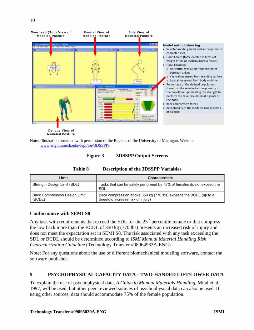
Several biomechanical models of different types are commercially available. One example of these models is the University of Michigan 3D Static Strength Prediction Program (3DSSPP; available through the University of Michigan Center for Ergonomics). Figure 3 displays the output screen depicting the task parameters, worker characteristics (anthropometry), and posture that are entered into the model, and some calculations such as low back compressive forces and percentage of the specified population with the strength to perform the task. Changes to the model parameters (hand forces, posture, etc.) are typically made by the user. Posture is most typically entered using some variation of videotape analysis (redesign scenario) or the creation of a reasonable posture based on known work area/task dimensions (design scenario). In some biomechanical models (the 3DSSPP being an example), postures may be predicted based on user-defined hand location using inverse kinematics algorithms.
10
Technology Transfer #09095029A-ENG ISMI
Frontal View of Modeled Posture
Overhead (Top) View of Modeled Posture
Side View of Modeled Posture
Model output showing: Selected model gender and anthropometric
characteristics
Hand Forces (force exerted in terms of weight lifted, or push/pull/press forces)
Hand Location: 1. Horizontal measured from mid‐point
between ankles 2. Vertical measured from standing surface3. Lateral measured from body mid‐line
Percentage of the defined population (based on the selected anthropometry of the population) possessing the strength to perform the task, calculated at 6 joints of the body
Back compressive forces
Acceptability of the modeled task in terms of balance
Oblique View of Modeled Posture
Note: Illustration provided with permission of the Regents of the University of Michigan. Website www.engin.umich.edu/dept/ioe/3DSSPP/.
Figure 3 3DSSPP Output Screens
Table 8 Description of the 3DSSPP Variables
Limit Characteristic
Strength Design Limit (SDL) Tasks that can be safely performed by 75% of females do not exceed the SDL
Back Compression Design Limit (BCDL)
Back compression above 350 kg (770 lbs) exceeds the BCDL (up to a threefold increase risk of injury)
Conformance with SEMI S8
Any task with requirements that exceed the SDL for the 25th percentile female or that compress the low back more than the BCDL of 350 kg (770 lbs) presents an increased risk of injury and does not meet the expectation set in SEMI S8. The risk associated with any task exceeding the SDL or BCDL should be determined according to ISMI Manual Material Handling Risk Characterization Guideline (Technology Transfer #08064933A-ENG).
Note: For any questions about the use of different biomechanical modeling software, contact the software publisher.
9 PSYCHOPHYSICAL CAPACITY DATA – TWO-HANDED LIFT/LOWER DATA
To explain the use of psychophysical data, A Guide to Manual Materials Handling, Mital et al., 1997, will be used, but other peer-reviewed sources of psychophysical data can also be used. If using other sources, data should accommodate 75% of the female population.

11
ISMI Technology Transfer #09095029A-ENG
Metric (kg, cm)
The data in Table 9 represent the maximum acceptable weight that 75% of the female workforce can be expected to handle without increased injury risk under various task conditions. To conduct the analysis,
Determine the vertical location of the hands at the start of the lift; use the appropriate data table that corresponds with this initial position (below 80 cm, between 80–132 cm, between 132–183 cm).
Determine the horizontal distance to the object as measured from the large knuckle at the end of the third finger to the ankle. Select the appropriate column for the measured horizontal distance (25–42 cm, 42–50 cm, or 50–63 cm). Body thickness is assumed to be 25 cm, aligning horizontal distance ranges with assumptions made in the NIOSH lifting equation).
Determine the vertical location of the hands at the end of the lift (below 80 cm, below 132 cm, above 132 cm).
Determine the lifting task frequency. The recommended weight limit is the intersection of the lifting task frequency and the vertical location at the end of lift.
Values between different lifting frequencies can be interpolated.

12
Technology Transfer #09095029A-ENG ISMI
Table 9 Recommended Weight of Lift (kg) for Two-Handed Symmetrical Lifting for an 8-hour Shift
Horizontal Distance [cm]
25 to 42 cm 42 to 50 cm 50 to 63 cm Vertical Location @ Start of Lift: Below 80 cm Vertical Location @ End of Lift Vertical Location @ End of Lift Vertical Location @ End of Lift
Frequency of Lift <80 cm <132 cm ≥132 cm <80 cm <132 cm ≥132 cm <80 cm <132 cm ≥132 cm
1 lift every 8 hours 19 16 14 16 13 12 14 12 11
1 lift every 30 minutes 14 12 10 12 10 9 11 9 8
1 lift every 5 minutes 13 11 10 10 8 7 10 8 7
1 lift per minute 12 10 9 10 8 7 9 8 7
4 lifts per minute 11 9 8 9 8 7 9 8 7
8 lifts per minute 9 8 7 8 7 6 8 7 6
12 lifts per minute 8 7 6 7 6 5 7 6 5
16 lifts per minute 7 6 5 6 5 5 6 5 5
Horizontal Distance [cm]
25 to 42 cm 42 to 50 cm 50 to 63 cm Vertical Location @ Start of Lift: Between 80 cm and 132 cm Vertical Location @ End of Lift Vertical Location @ End of Lift Vertical Location @ End of Lift
Frequency of Lift <80 cm <132 cm ≥132 cm <80 cm <132 cm ≥132 cm <80 cm <132 cm ≥132 cm
1 lift every 8 hours 16 17 15 13 15 13 12 15 13
1 lift every 30 minutes 12 14 12 10 13 11 9 13 11
1 lift every 5 minutes 11 13 11 8 12 11 8 12 11
1 lift per minute 10 12 11 8 11 10 8 11 10
4 lifts per minute 9 11 10 8 9 8 8 9 8
8 lifts per minute 8 9 8 7 7 6 7 7 6
12 lifts per minute 7 9 8 6 7 6 6 7 6
16 lifts per minute 6 8 7 5 6 5 5 6 5
Horizontal Distance [cm]
25 to 42 cm 42 to 50 cm 50 to 63 cm Vertical Location @ Start of Lift: Between 132 cm and 183 cm Vertical Location @ End of Lift Vertical Location @ End of Lift Vertical Location @ End of Lift
Frequency of Lift <80 cm <132 cm ≥132 cm <80 cm <132 cm ≥132 cm <80 cm <132 cm ≥132 cm
1 lift every 8 hours 14 15 14 12 12 13 11 13 11
1 lift every 30 minutes 10 12 12 9 10 11 8 11 9
1 lift every 5 minutes 10 11 11 7 9 11 7 11 9
1 lift per minute 9 11 11 7 9 10 7 10 8
4 lifts per minute 8 10 9 7 8 8 7 8 8
8 lifts per minute 7 8 7 6 6 6 6 6 6
12 lifts per minute 6 8 7 5 5 6 5 6 5
16 lifts per minute 5 7 7 5 4 5 5 5 4

13
ISMI Technology Transfer #09095029A-ENG
U.S. Standard (lbs, inches)
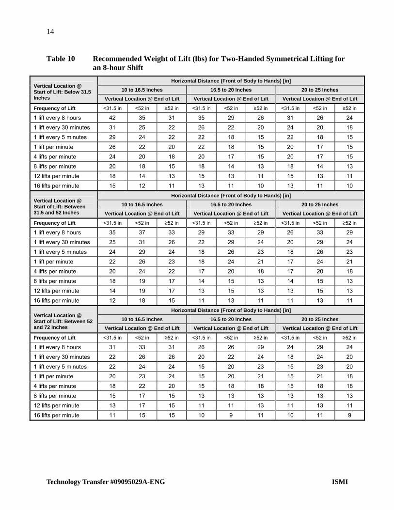
The data in Table 10 represent the maximum acceptable weight that 75% of the female workforce can be expected to handle without increased injury risk under various task conditions. To conduct the analysis,
Determine the vertical location of the hands at the start of the lift; use the appropriate data table that corresponds with this initial position (below 31.5 inches, between 31.5–52 inches, between 52–72 inches).
Determine the horizontal distance to the object as measured from the large knuckle at the end of the third finger to the ankle. Select the appropriate column for the measured horizontal distance (10–16.5 inches, 16.5–20 inches, or 20–25 inches. Body thickness is assumed to be 10 inches, aligning horizontal distance ranges with assumptions made in the NIOSH lifting equation).
Determine the vertical location of the hands at the end of the lift (below 31.5 inches, below 52 inches, above 52 inches).
Determine the lifting task frequency. The recommended weight limit is the intersection of the lifting task frequency and the vertical location at the end of lift.
Values between different lifting frequencies can be interpolated.
14
Technology Transfer #09095029A-ENG ISMI
Table 10 Recommended Weight of Lift (lbs) for Two-Handed Symmetrical Lifting for an 8-hour Shift
Horizontal Distance (Front of Body to Hands) [in]
10 to 16.5 Inches 16.5 to 20 Inches 20 to 25 Inches Vertical Location @ Start of Lift: Below 31.5 Inches Vertical Location @ End of Lift Vertical Location @ End of Lift Vertical Location @ End of Lift
Frequency of Lift <31.5 in <52 in ≥52 in <31.5 in <52 in ≥52 in <31.5 in <52 in ≥52 in
1 lift every 8 hours 42 35 31 35 29 26 31 26 24
1 lift every 30 minutes 31 25 22 26 22 20 24 20 18
1 lift every 5 minutes 29 24 22 22 18 15 22 18 15
1 lift per minute 26 22 20 22 18 15 20 17 15
4 lifts per minute 24 20 18 20 17 15 20 17 15
8 lifts per minute 20 18 15 18 14 13 18 14 13
12 lifts per minute 18 14 13 15 13 11 15 13 11
16 lifts per minute 15 12 11 13 11 10 13 11 10
Horizontal Distance (Front of Body to Hands) [in]
10 to 16.5 Inches 16.5 to 20 Inches 20 to 25 Inches Vertical Location @ Start of Lift: Between 31.5 and 52 Inches Vertical Location @ End of Lift Vertical Location @ End of Lift Vertical Location @ End of Lift
Frequency of Lift <31.5 in <52 in ≥52 in <31.5 in <52 in ≥52 in <31.5 in <52 in ≥52 in
1 lift every 8 hours 35 37 33 29 33 29 26 33 29
1 lift every 30 minutes 25 31 26 22 29 24 20 29 24
1 lift every 5 minutes 24 29 24 18 26 23 18 26 23
1 lift per minute 22 26 23 18 24 21 17 24 21
4 lifts per minute 20 24 22 17 20 18 17 20 18
8 lifts per minute 18 19 17 14 15 13 14 15 13
12 lifts per minute 14 19 17 13 15 13 13 15 13
16 lifts per minute 12 18 15 11 13 11 11 13 11
Horizontal Distance (Front of Body to Hands) [in]
10 to 16.5 Inches 16.5 to 20 Inches 20 to 25 Inches Vertical Location @ Start of Lift: Between 52 and 72 Inches Vertical Location @ End of Lift Vertical Location @ End of Lift Vertical Location @ End of Lift
Frequency of Lift <31.5 in <52 in ≥52 in <31.5 in <52 in ≥52 in <31.5 in <52 in ≥52 in
1 lift every 8 hours 31 33 31 26 26 29 24 29 24
1 lift every 30 minutes 22 26 26 20 22 24 18 24 20
1 lift every 5 minutes 22 24 24 15 20 23 15 23 20
1 lift per minute 20 23 24 15 20 21 15 21 18
4 lifts per minute 18 22 20 15 18 18 15 18 18
8 lifts per minute 15 17 15 13 13 13 13 13 13
12 lifts per minute 13 17 15 11 11 13 11 13 11
16 lifts per minute 11 15 15 10 9 11 10 11 9

15
ISMI Technology Transfer #09095029A-ENG
Use of Psychophysical Multipliers
Other circumstances of the lift may affect the amount of weight the worker should lift. Common factors are listed in Table 11 with instructions for determining multipliers for each condition. The RWL is multiplied by each of the multipliers to determine the Final RWL (RWL). Less than optimal conditions result in a multiplier less than 1, which reduces the FRWL. Factors are listed below with the associated abbreviation and a brief description:
1. Work Duration (WD) is the number of hours the task will be performed in a workers shift.
2. Limited Headroom (LH) is a measure of how cramped a worker’s posture is because of low overhead clearance.
3. Asymmetrical Lifting (AL) indicates twisting with a suspended load.
4. Coupling (CP) indicates how well the hands connect with the load.
5. Load Placement Clearance (LPC) is a determination of how precisely the load must be handled because of clearances at the destination of the load.

16
Technology Transfer #09095029A-ENG ISMI
Table 11 Multipliers for Psychophysical Data
Multiplier Description
Working Duration (Hours) Duration (Hours)
Not all MMH tasks are performed across the entire duration of the shift, and shift lengths differ. Use the multipliers below to adjust for this. Interpolate as required. The working duration multiplier should not be used if you are dealing with a lift/lower that occurs only once per 8 hours.
1 4 8 12
1.140 1.080 1.000 0.920
Limited Headroom Multiplier (Applies to two hand lifting only) % Upright Height cm (in) Multiplier
If the work environment does not permit the worker to assume an upright posture during handling, use the limited headroom multipliers. Interpolate as required. Note that the limited headroom multiplier would be applied only for situations where the lift would permit the worker to stand upright if there was not a headroom restriction.
FullyUpright
80%Upright
100% 186 (73.2) 1.00
95% 177 (69.5) 0.60
90% 167 (65.8) 0.40
85% 158 (62.2) 0.38
80% 149 (58.6) 0.36
Asymmetrical Lifting (Twisting) Multiplier (Applies to two hand lifting only) Angle of Turn (Degrees) Multiplier
If twisting occurs, use the adjustment factors. The following assumptions apply:
Angle of twist measured from straight line drawn between the ankles to the midpoint of the container. Start and end points of lift must be considered.
The 30–90 adjustment factor assumes feet do not move and may be too high if feet move.
The “Above 90” adjustment factor assumes people move their feet.
0–30 1.000
30–60 0.924
60–90 0.848
Greater than 90 0.800
0°–0°
31°–60°
61°–90°
>90°
Coupling Multiplier Coupling (Handles) Multiplier
The RWL data assume that good quality handles are provided for the user’s hands to couple with the load. If that is not the case, the appropriate multiplier should be used. If there is any question about the appropriate classification, use the lesser of the classifications in question.
If tight-fitting elastic cleanroom type gloves are worn, the quality of the coupling should be decremented to the next lower classification than would be used if no gloves were worn.
Good 1.000
Poor 0.925
No handles 0.850
Load Placement Clearance Multiplier (Applies to two hand lifting only) Load Clearance Multiplier in cm (Inches)
If a load has to be positioned in a location where the clearance around the object is limited, a precision component is added to the task that effectively reduces capacity. A clearance of (e.g.) 1.5 cm refers to the clearance on both sides of the object handled. Interpolate for intermediate values.
Unlimited to 3 cm (1.2 inches) 1.00
1.5 cm (0.6 inches) 0.91
0.3 cm (0.1 inches) 0.87
Load Asymmetry Multiplier (Applies to two hand lifting and carrying only) Load Asymmetry Multiplier in cm (Inches)
Adjustment for loads where the center of mass is not centered in the object (i.e., a different load in each hand). The center of gravity shift is measured from physical midpoint of the object being lifted. Interpolate for intermediate values.
0 cm (0 inches) 1.00
10 cm (3.9 inches) 0.96
20 cm (7.9 inches) 0.89
30 cm (11.8 inches) 0.84

17
ISMI Technology Transfer #09095029A-ENG
Calculation of the Final RWL
A simple equation describes how each of these multipliers is used to get the FRWL:
RWL WD LH AL CP = FRWL
Lifting Index
The lifting index (LI) provides a simple estimate of the hazard of overexertion injury for a manual lifting job.
LI = Load Weight FRWL
Two-person Lifting
Two-person lifting can be assessed with either the 1991 NIOSH equation or psychophysical lifting data. A separate analysis should be performed for each person if any of the parameters of the analysis model (e.g., horizontal reach, vertical location, etc.) are different. Each person in a two-person lift can lift only 90% of the amount that person could lift in a similar posture lifting alone.
FRWL Adjusted = 0.90 FRWL Calculated
Also, a lifting index should be calculated for the FRWL for each person:
LI Person 1 = (½ actual weight) ÷ (0.90 FRWL Person 1)
LI Person 2 = (½ actual weight) ÷ (0.90 FRWL Person 2)
The acceptability of the task should be based on the larger of the two lifting indices. Risk characterization for the task is the same as single-person lifting using the larger of the two lifting indices.
Conformance with SEMI S8
Any task with a lifting index greater than 1.0 presents an increased risk of injury and does not meet the expectation set in SEMI S8. The risk associated with any task with a lifting index greater than 1.0 should be determined according to ISMI Manual Material Handling Risk Characterization Guideline (Technology Transfer #08064933A-ENG).
10 PSYCHOPHYSICAL CAPACITY DATA –
The one-hand lift forces shown in Table 12 and Table 13 take into account the worker’s posture (stand/squat/sit/kneel), reach distance (shoulder-grip distance, handling frequency (F greater than or less than 1 lift per minute), and age. These forces can be applied when the arm is in front of the body in the horizontal plane of the shoulder and when the arm is held to the side of the body. The forces are for the preferred hand; for the non-dominant hand, reduce the values by 10%. The data are for the 5th percentile female.
ONE-HAND LIFT DATA

18
Technology Transfer #09095029A-ENG ISMI
Table 12 One-Hand Lift Data Infrequent Lifts (F <1 lift per minute)
Position Shoulder – Grip Distance RWL
65 cm (25.6 in) 5.9 kg (12.9 lbs)
60 (23.6) 7.2 (15.7)
50 (19.7) 8.5 (18.6)
35 (13.8) 11.7 (25.7)
20 (7.9) 14.3 (31.5)
Standing/Squatting
5 (2.0) 17.6 (38.6)
65 (25.6) 5.2 (11.4)
50 (19.7) 7.8 (17.2)
40 (15.7) 10.4 (22.9)
30 (11.8) 13 (28.6)
15 (5.9) 15.6 (34.3)
Sitting
5 (2.0) 18.2 (40)
65 (25.6) 5.9 (12.9)
60 (23.6) 7.2 (15.7)
55 (21.6) 7.8 (17.2)
30 (11.8) 9.8 (21.5)
25 (9.8) 11.7 (25.7)
Kneeling on One Knee
15 (5.9) 14.3 (31.5)
Note: Lifting forces in kg (lbs) for one-handed lift with arm in the front of the body in the horizontal plane of the shoulder.
Table 13 One-Hand Lift Data Frequent Lifts (F >1 lift per minute)
Position Shoulder – Grip Distance RWL
65 cm (25.6 in) 4.1 kg (9 lbs)
60 (23.6) 5 (11)
50 (19.7) 5.9 (12.9)
35 (13.8) 8.2 (18)
20 (7.9) 10 (22)
Standing/Squatting
5 (2.0) 12.3 (27)
65 (25.6) 3.6 (8)
50 (19.7) 5.5 (12)
40 (15.7) 7.3 (16)
30 (11.8) 9.1 (20)
15 (5.9) 11.1 (24.3)
Sitting
5 (2.0) 12.7 (28)
65 (25.6) 4.1 (9)
60 (23.6) 5 (11)
55 (21.6) 5.5 (12)
30 (11.8) 6.8 (15)
25 (9.8) 8.2 (18)
Kneeling on One Knee
15 (5.9) 10 (22)
Note: Lifting Forces in kg (lbs) for one-handed lift with arm in the front of the body in the horizontal plane of the shoulder.

19
ISMI Technology Transfer #09095029A-ENG
11 PSYCHOPHYSICAL CAPACITY DATA – TWO-HAND PULL DATA
Table 14 presents the maximum initial and sustained forces that can be exerted by 75% of the female population based on the task characteristics. Each cell gives two values: 1) the maximum acceptable initial pull force that can be exerted and 2) the sustained force that can be acceptably maintained across the distance/duration (number in parentheses). Initial force is defined as the force to get the object in motion; sustained force is defined as the force to maintain the object in motion. If the pull distances are not known, the evaluator should measure and document the required pull force and determine the maximum acceptable pull distance based on frequency.
The variables include the following:
Pull distance 2.1 to 61 meters (7 feet to 200 feet)
Frequency of pull (once every 6 seconds to once per 8-hour period)
Floor-to-hand height (knee level, elbow level, shoulder level)
Initial vs. sustained forces
Note: If cleanroom gloves are worn, the table values should be reduced by 15% for pull tasks only.

20
Technology Transfer #09095029A-ENG ISMI
Table 14 Maximum Acceptable Two-Hand Pull Forces, Initial (Sustained) Forces
Frequency: One Pull Every… (Metric – Meters, kg) Floor-to-Hand Height
Pull Distance (Meters) 6 sec 12 sec 1 min 2 min 5 min 30 min 8 hr
2.1 16(7) 19(10) 20(13) 21(14) 24(15) 25(16) 26(20)
7.6 X X 19(12) 19(12) 21(13) 22(14) 24(18)
15.2 X X 16(9) 16(10) 18(11) 19(12) 20(15)
30.5 X X 14(7) 16(9) 17(10) 18(10) 20(14)
45.7 X X 14(6) 16(9) 17(9) 18(9) 20(12)
Shoulder Level
61 X X X 14(6) 15(7) 16(7) 18(10)
2.1 16(7) 19(10) 21(13) 22(13) 25(15) 26(16) 27(19)
7.6 X X 19(11) 20(12) 22(13) 23(14) 25(17)
15.2 X X 17(9) 17(10) 19(11) 20(12) 21(14)
30.5 X X 15(7) 16(9) 18(9) 19(10) 21(13)
45.7 X X 15(6) 16(8) 18(9) 19(9) 21(12)
Elbow Level
61 X X X 15(5) 16(7) 17(7) 19(9)
2.1 17(6) 20(9) 22(12) 23(12) 26(13) 27(14) 28(18)
7.6 X X 20(11) 21(11) 23(12) 24(13) 26(16)
15.2 X X 17(8) 18(9) 20(10) 21(11) 22(13)
30.5 X X 16(6) 17(8) 18(9) 20(9) 22(12)
45.7 X X 16(6) 17(8) 18(8) 20(8) 22(11)
Knee Level
61 X X X 15(5) 16(6) 18(6) 20(9)
Frequency: One Pull Every… (U.S. Standard – Feet, lbs) Floor-to-Hand Height
Pull Distance
(Feet) 6 sec 12 sec 1 min 2 min 5 min 30 min 8 hr
7 35(15) 42(22) 44(29) 46(31) 53(33) 55(35) 57(44)
25 X X 42(26) 42(26) 46(29) 48(31) 53(40)
50 X X 35(20) 35(22) 40(24) 42(26) 44(33)
100 X X 31(15) 35(20) 37(22) 40(22) 44(31)
150 X X 31(13) 35(20) 37(20) 40(20) 44(26)
Shoulder Level
200 X X X 31(13) 33(15) 35(15) 40(22)
7 35(15) 42(22) 46(29) 48(29) 55(33) 57(35) 59(42)
25 X X 42(24) 44(26) 48(29) 51(31) 55(37)
50 X X 37(20) 37(22) 42(24) 44(26) 46(31)
100 X X 33(15) 35(20) 40(20) 42(22) 46(29)
150 X X 33(13) 35(18) 40(20) 42(20) 46(26)
Elbow Level
200 X X X 33(11) 35(15) 37(15) 42(20)
7 37(13) 44(20) 48(26) 51(26) 57(29) 59(31) 62(40)
25 X X 44(24) 46(24) 51(26) 53(29) 57(35)
50 X X 37(18) 40(20) 44(22) 46(24) 48(29)
100 X X 35(13) 37(18) 40(20) 44(20) 48(26)
150 X X 35(13) 37(18) 40(18) 44(18) 48(24)
Knee Level
200 X X X 33(11) 35(13) 40(13) 44(20)
Note: An “X” in a cell indicates the pull distance cannot be performed for the frequency pull.

21
ISMI Technology Transfer #09095029A-ENG
12 PSYCHOPHYSICAL CAPACITY DATA–TWO-HAND PUSH DATA
Table 15 and Table 16 present the maximum initial and sustained forces that can be exerted by 75% of the female population based on the task characteristics. Each cell gives two values: 1) the maximum acceptable initial pull force that can be exerted and 2) the sustained force that can be acceptably maintained across the distance/duration (number in parentheses). Initial force is defined as the force to get the object in motion; sustained force is defined as force to maintain motion. If the push distances are not known, the evaluator should measure and document the required push force and determine the maximum acceptable push distance based on frequency.
The variables include the following:
Push distance 2.1 to 61 meters (7 feet to 200 feet)
Frequency of push (once every 6 seconds to once every 8-hour period)
Floor-to-hand height (knee level, elbow level, shoulder level)

22
Technology Transfer #09095029A-ENG ISMI
Table 15 Maximum Acceptable Two-Hand Push Forces Initial (Sustained) Forces
Frequency: One Push Every... (Metric – Meters, kg) Floor-to-Hand Height
Push Distance (Meters) 6 sec 12 sec 1 min 2 min 5 min 30 min 8 hr
2.1 17(8) 18(10) 21(14) 22(14) 24(16) 25(17) 27(21)
7.6 X X 19(11) 20(11) 22(12) 23(13) 24(16)
15.2 X X 17(8) 17(9) 19(10) 20(11) 21(13)
30.5 X X 15(6) 16(8) 17(9) 19(9) 21(12)
45.7 X X 15(6) 16(8) 17(8) 19(8) 21(11)
61 X X X 14(4) 15(6) 17(6) 19(9)
91.4 X X X X 15(5) 16(6) 19(7)
121.9 X X X X 14(4) 16(5) 18(6)
152.4 X X X X 13(3) 15(5) 17(6)
228.6 X X X X X 15(5) 16(5)
304.8 X X X X X 14(4) 16(5)
381 X X X X X 13(4) 15(4)
457.2 X X X X X 13(4) 15(4)
533.4 X X X X X 12(4) 15(4)
Shoulder Level
609.6 X X X X X 12(3) 15(4)
2.1 17(7) 18(9) 21(13) 22(13) 24(15) 25(16) 27(19)
7.6 X X 20(11) 20(11) 22(13) 23(13) 25(17)
15.2 X X 17(8) 17(10) 19(11) 20(11) 21(14)
30.5 X X 15(7) 16(9) 18(9) 19(10) 21(13)
45.7 X X 15(6) 16(8) 18(8) 19(9) 21(12)
61 X X X 15(4) 16(6) 17(7) 19(9)
91.4 X X X X 15(5) 16(7) 19(8)
121.9 X X X X 15(4) 16(6) 18(7)
152.4 X X X X 15(3) 15(5) 17(7)
228.6 X X X X X 15(5) 16(6)
304.8 X X X X X 14(4) 16(4)
381 X X X X X 13(3) 15(3)
Elbow Level
457.2 X X X X X 13(3) 15(3)
2.1 14(6) 15(8) 17(11) 17(11) 19(13) 20(14) 21(17)
7.6 X X 17(10) 17(11) 19(12) 20(12) 21(15)
15.2 X X 14(8) 15(9) 16(10) 17(10) 18(13)
30.5 X X 13(6) 14(8) 15(8) 16(9) 18(12)
45.7 X X 13(6) 14(7) 15(8) 16(8) 18(11)
Knee Level
61 X X X 12(4) 13(6) 14(6) 16(8)
Note: An “X” in a cell indicates the pull distance cannot be performed for the frequency push. Continuous pushing beyond the distances listed in the table is not recommended.
23
ISMI Technology Transfer #09095029A-ENG
Table 16 Maximum Acceptable Two-Hand Push Forces Initial (Sustained) Forces
Frequency: One Push Every… (US Standard – feet, lbs) Floor-to-Hand Height
Push Distance
(feet) 6 sec 12 sec 1 min 2 min 5 min 30 min 8 hr
7 37(18) 40(22) 46(31) 48(31) 53(35) 55(37) 59(46)
25 X X 42(24) 44(24) 48(26) 51(29) 53(35)
50 X X 37(18) 37(20) 42(22) 44(24) 46(29)
100 X X 33(13) 35(18) 37(20) 42(20) 46(26)
150 X X 33(13) 35(18) 37(18) 42(18) 46(24)
200 X X X 31(9) 33(13) 37(13) 42(20)
300 X X X X 32(10) 36(13) 41(15)
400 X X X X 30(9) 35(12) 39(14)
500 X X X X 28(6) 34(11) 38(13)
750 X X X X X 32(10) 36(11)
1000 X X X X X 30(9) 35(10)
1250 X X X X X 29(8) 34(8)
1500 X X X X X 28(8) 33(8)
1750 X X X X X 27(8) 32(8)
Shoulder Level
2000 X X X X X 27(7) 32(8)
7 37(15) 40(20) 46(29) 48(29) 53(33) 55(35) 59(42)
25 X X 44(24) 44(24) 48(29) 51(29) 55(37)
50 X X 37(18) 37(22) 42(24) 44(24) 46(31)
100 X X 33(15) 35(20) 40(20) 42(22) 46(29)
150 X X 33(13) 35(18) 40(18) 42(20) 46(26)
200 X X X 33(9) 35(13) 37(15) 42(20)
300 X X X X 34(11) 36(15) 41(18)
400 X X X X 33(9) 35(13) 39(16)
500 X X X X 32(6) 34(12) 38(15)
750 X X X X X 32(10) 36(13)
1000 X X X X X 30(9) 35(9)
1250 X X X X X 29(7) 34(7)
Elbow Level
1500 X X X X X 28(7) 33(7)
7 31(13) 33(18) 37(24) 37(24) 42(29) 44(31) 46(37)
25 X X 37(22) 37(24) 42(26) 44(26) 46(33)
50 X X 31(18) 33(20) 35(22) 37(22) 40(29)
100 X X 29(13) 31(18) 33(18) 35(20) 40(26)
150 X X 29(13) 31(15) 33(18) 35(18) 40(24)
Knee Level
200 X X X 26(9) 29(13) 31(13) 35(18)
Note: An “X” in a cell indicates the pull distance cannot be performed for the frequency push. Continuous pushing beyond the distances listed in the table is not recommended.

24
Technology Transfer #09095029A-ENG ISMI
13 PSYCHOPHYSICAL CAPACITY DATA – ONE-HAND PUSH/PULL FORCES
The capacity data below assume the following:
The worker is standing.
The dominant (stronger) hand is being used. If the non-dominant hand is used, reduce the values by 10%.
One-hand Push
If the push force is exerted less than once per minute, the recommended value is 11 kg (24 lbs).
If the push force is exerted more frequently than once per minute, the recommended value is 7.5 kg (16.5 lbs).
One-hand Pull
If the pull force is exerted less than once per minute, the recommended value is 10 kg (22 lb).
If the pull force is exerted more frequently than once per minute, the recommended value is 7 kg (15 lb).
Note: If cleanroom gloves are worn, reduce the above values by 15% for pull tasks only.
14 PSYCHOPHYSICAL CAPACITY DATA – KNEELING TASKS
The recommended weight of lift is based on the lifting capacity of 75% of the female population. Table 17 summarizes the recommended weight of lift for kneeling tasks. The assessor should select the activity description that best represents the actual task parameters being assessed.

25
ISMI Technology Transfer #09095029A-ENG
Table 17 Recommended Weight Limit (RWL) for Kneeling Tasks
Task Description RWL – kg (lb)
1. Lift kneeling on 2 knees floor to 0.6 m (24 inches) 1 7.7 (17.2)
The subject was positioned on both knees between the box and the shelf. The subject twisted 90° to the left, picked up the box, twisted 180° to the right, and lifted the box onto the shelf. Frequency of lift was 6 lifts per minute.
2. Lift kneeling on 1 knee floor to 0.6 m (24 inches) 1 7.6 (17.0)
The subject was positioned in a kneeling posture (left knee on the floor) between the box and the shelf. The subject twisted 90° to the left, picked up the box, twisted 180 to the right, and lifted the box onto the shelf. Frequency of lift was 6 lifts per minute.
3. Horizontal transfer kneeling on 2 knees 1 8.0 (17.9)
Subject knelt on both knees, twisted 90 to the left, picked the box up from the floor, twisted 180 to the right, and lowered the box back onto the floor. Frequency of lift was 6 lifts per minute.
4. Lower kneeling on 2 knees 0.6 m (24 inches) to floor 1 (Reverse of #1 above) 8.6 (19)
5. Kneeling 1 knee, 2 hands lift floor to:
35% Functional Reach 2 flat container 6130.515 cm (24126 inches) 2 20 (44.0)
60% Functional Reach 15.9 (35.6)
85% Functional Reach 13.6 (30.5)
35% Functional Reach vertical container 30.51561 cm (12624 inches) 2 20 (44.0)
60% Functional Reach 15.9 (35.6)
85% Functional Reach 12 (26.9)
35% Functional Reach deep container 156130.5 cm (62512 inches) 2 20 (44.0)
60% Functional Reach 18.1 (40.5)
85% Functional Reach 13.6 (30.5)
The subject was instructed to kneel with the left knee on the floor and the right knee up. The subject bent over, grasped the handle of the box, picked the box up off the floor, lifted the box, and placed it on a shelf adjusted in height to 35, 60, and 85% of the subject’s kneeling vertical reach. The subject was required to place precisely the box on the shelf without touching the clearance guides. The box size was 6130.515 cm (24126 inches), and lift was repeated for each possible box orientations. Frequency is 1 lift/8 hours.
6. Kneeling 2 knees, 2 hands lift floor to:
35% Functional Reach flat container 6130.515 cm (24126 inches) 2 20 (44.0)
60% Functional Reach 16 (35.2)
85% Functional Reach 13.6 (30.5)
35% Functional Reach vertical container 30.51561 cm (12624 inches) 2 18.1 (40.5)
60% Functional Reach 15.9 (35.6)
85% Functional Reach 12.2 (27.3)
35% Functional Reach deep container 156130.5 cm (62412 inches) 2 20 (44.0)
60% Functional Reach 18.1 (40.5)
85% Functional Reach 13.6 (30.5)
The subject was instructed to kneel with both knees on the floor. The box was located in front of the subject with the box as close to the knees as was comfortable to the subject. The subject bent over, picked the box up off the floor, lifted the box, and placed it on a shelf adjusted in height to 35, 60, and 85% of the subject's kneeling vertical reach. The subject was required to place the box precisely on the shelf without touching the clearance guides. The box size was 6130.515 cm (24126 inches), and the lift was repeated for each of the three possible box orientations. Frequency is 1 lift per 8 hours.
1 Frequency = 6 lifts per minute 2 Frequency = 1 lift every 8 hours

26
Technology Transfer #09095029A-ENG ISMI
Table 17 Recommended Weight Limit (RWL) for Kneeling Tasks (continued)
Task Description RWL – kg (lb)
7. Kneeling 1 knee, 1 hand lift floor to: 2
35% Functional Reach 6 (13.0)
60% Functional Reach 6 (13.0)
85% Functional Reach 6 (13.0)
The subject was instructed to kneel with the left knee on the floor and the right knee up. The subject bent over, grasped the handle of the box with one hand, picked the box up off the floor, lifted the box, and placed it on a shelf adjusted in height to 35, 60, and 85% of the subject's kneeling vertical reach. The subject was required to place the box precisely on the shelf without touching the clearance guides. Frequency is 1 lift per 8 hours.
8. Kneeling 2 knees, 1 hand lift floor to: 2
35% Functional Reach 6 (13.0)
60% Functional Reach 6 (13.0)
85% Functional Reach 6 (13.0)
The subject was instructed to kneel with both the knees on the floor. The subject bent over, grasped the handle of the box with one hand, picked the box up off the floor, lifted the box, and placed it on a shelf that was adjusted in height to 35, 60, and 85% of the subject's kneeling vertical reach. The subject was required to precisely place the box on the shelf without touching the clearance guides. Frequency of lift was 1 lift per 8 hours.
1 Frequency = 6 lifts per minute 2 Frequency = 1 lift every 8 hours
Flat container Vertical container Deep container
305 mm(12 in.)
152 mm(6 in.)
152 mm(6 in.)
610 mm(24 in.)
610 mm(24 in.)
305 mm(12 in.)
Note: Referenced in Table 17
Figure 4 Description of Container Orientations (Flat, Vertical, Deep)

27
ISMI Technology Transfer #09095029A-ENG
15 PSYCHOPHYSICAL CAPACITY DATA – SEATED TASKS
The recommended weight of lift is based on the lifting capacity of 75% of the female population. Table 18 summarizes the recommended weight of lift for sitting tasks. Unless a handle is specifically mentioned, it should be assumed that handles are unavailable. The assessor should select the activity description that best represents the actual task parameters being assessed.
Table 18 Recommended Weight of Lifts for Sitting Tasks
Task Description RWL – kg (lb)
1. Horizontal transfer seated 1 7.4 (16.6)
The subjects sat on the floor with legs extended straight in front of him or her, twisted 90 to the left, picked the box up off the floor, twisted 180 degrees to the right, and placed the box back onto the floor. Frequency is 6 lifts per minute.
2. Sitting 2 hands lift floor to:
35% Functional Reach flat container 6130.515 cm (24126 inches) 2 20.0 (44.0)
60% Functional Reach 15.9 (35.6)
85% Functional Reach 13.6 (30.5)
35% Functional Reach vertical container 30.51561 cm (12624 inches) 2 18.1 (40.5)
60% Functional Reach 13.6 (30.5)
85% Functional Reach 10.9 (24.4)
35% Functional Reach deep container 156130.5 cm (62412 inches) 2 18.1 (40.5)
60% Functional Reach 15.9 (35.6)
85% Functional Reach 13.6 (30.5)
The subject was instructed to sit on a 30.5 cm (12 inches) high surface. The subject bent over, picked the box up off the floor, lifted the box, and placed it on a shelf adjusted in height to 35, 60, and 85% of the subject's sitting vertical reach. The subject was required to place the box precisely on the shelf without touching the clearance guides. The box size was 6130.515 cm (24126 inches), and the lift was repeated for each of the three possible box orientations. Frequency of lift was one lift per 8 hours.
3. Sitting 1 hand lift floor to 35%, 60%, or 85% Functional Reach 2 6.0 (13.0)
The subject was instructed to sit on a 30.5 cm (12 inches) high surface. The subject bent over, grasped the handle of the box with their right hand, picked the box up off the floor, lifted the box, and placed it on a shelf that was adjusted in height to 35, 60, and 85% of the subject's sitting vertical reach. The subject was required to place the box precisely on the shelf without touching the clearance guides. Frequency of lift was one lift per 8 hours.
1 Frequency = 6 lifts per minute 2 Frequency = 1 lift every 8 hours
16 PSYCHOPHYSICAL CAPACITY DATA – LYING TASKS
The recommended weight of lift is based on the lifting capacity of 75% of the female population. Table 19 summarizes the recommended weight of lift for lying tasks. Unless a handle is specifically mentioned, it should be assumed that handles are unavailable. Recommended forces are based on symmetric distribution of weight about the handle. The assessor should select the activity description that best represents the actual task parameters being assessed.

28
Technology Transfer #09095029A-ENG ISMI
Table 19 Recommended Weight Limit (RWL) for Lying Tasks Task Description RWL – kg (lb)
1. Lying face down, lift with one hand: Lift with left hand 7.5 (16.8) Lift with right hand 7.5 (16.8) The subject lay prone on a 122 cm (48 inches) high platform and extends his or her arm through a 35.635.6 cm (1414 inches) opening in the platform. With the arm fully extended, the subject grasped the pipe handle of a 25.425.4 cm (1010 inches) box (30.5 cm (1 inch) high) and lifted it through the opening and placed it on the platform. The container with the pipe handle was similar to a small tool box or tray with a handle extending the full width of the container. The subject was allowed to prop up his or her body using the forearms. The task was repeated for both the left and right arm.
2. One hand lying side lift: Close 5.4 (12.1) Far 5.7 (12.8) The subject was instructed to lay on his or her left side on the floor with the body parallel to a 52.4 cm (1 inch) high platform. The distance between the platform and the subject was defined as the functional reach of the subject. Using the right hand, the subject grasped the handle of a 35.62012.7 cm (1485 inches) box and lifted it onto the platform. Two starting positions for the box were used, designated as close and far. For the close position, the rear edge of the box was placed against the body of the subject. For the far position, the subject extended his or her right hand so that the elbow could be located. The box was positioned such that the rear edge of the box was in line with the elbow.
3. Two hands lying side lift: Close 6.6 (14.8) Far 7.5 (16.8) The subject was instructed to lie on his or her left side with the body parallel to a 25.4 cm (1 inch) high platform. The distance between the platform and the subject was defined as the functional reach of the subject. Using both hands, the subject grasped a 20.320.320.3 cm (888 inches) box and lifted it onto the platform. Two starting positions for the box were used, designated as close and far. For the close position, the rear edge of the box was placed against the body of the subject. For the far position, the subject extended his or her right hand so that the elbow could be located. The box was positioned such that the rear edge of the box was in line with the elbow.
4. One hand lying face up lift: Close 7.5 (16.8) Far 10.4 (23.3) The subject was asked to lie flat on his or her back on an exercise bench. The subject placed the palm of his or her hand on the bottom of a 25.425.420.3 cm (10x10x8 inches) box suspended over the right shoulder of the subject. The subject lifted the box until the arm was fully extended. Two starting positions for the box were used, designated as close and far. For the close position, the box was suspended approximately 10 cm (4 inches) above the subject's right shoulder. For the far position, the subject extended the right arm so that the elbow could be located. The box was suspended such that the bottom of the box was at the height of the elbow.
5. Two hands lying face up lift: Close 20.9 (46.8) Far 26.1 (58.5) The subject was asked to lie flat on his or her back on an exercise bench. The subject placed his or her hands on the bottom of a 45.730.525.4 cm (181210 inches) box suspended over the chest of the subject. The subject lifted the box until the arms were fully extended. Two starting positions for the box were used, designated as close and far. For the close position, the box was suspended as close to the subject's chest as possible, still allowing the subject to grasp the bottom edge of the box. For the far position, the subject extended the right arm so that the elbow could be located. The box was suspended such that the bottom of the box was at the height of the elbow.
Note: Frequency for all tasks = 1 lift/8 hours


International SEMATECH Manufacturing Initiative Technology Transfer
2706 Montopolis Drive Austin, TX 78741
http://ismi.sematech.org e-mail: [email protected]