Application Guide ABB MaxSB Low Voltage Switchboard · PDF file2 ABB MaxSB Low Voltage...
40
ABB MaxSB Low Voltage Switchboard Application Guide
Transcript of Application Guide ABB MaxSB Low Voltage Switchboard · PDF file2 ABB MaxSB Low Voltage...
ABB MaxSBLow Voltage Switchboard
Application Guide
2 ABB MaxSB Low Voltage Switchboard Application Guide
Product Description ...................................................................... 4 System Overview ........................................................................ 4 Standards ................................................................................... 4 Ratings ....................................................................................... 5 Ambient Conditions ..................................................................... 5 Overall System Derating .............................................................. 5 Emax Breaker Loss ..................................................................... 6 Tmax Breaker Loss ..................................................................... 6 Emax Breaker Temperature Derating ............................................ 6
Technical Data .............................................................................. 7 Standard finish ............................................................................ 7 Frame......................................................................................... 7 Available Dimensions ................................................................... 7 Shipping design .......................................................................... 8 Doors and covers........................................................................ 8 Barriers ...................................................................................... 8 Nameplates ................................................................................ 9 Enclosure .................................................................................. 9 Bus Bar System .......................................................................... 10 Incoming Connections ................................................................. 11 Wiring ........................................................................................ 11 Voltage Transformer – External Metering and Relaying .................. 12 Control Power Transformer .......................................................... 12 Current Transformers .................................................................. 13 Zero Sequence Current Transformers and Ground Fault Relays ...................................................................................... 13 Metering ..................................................................................... 13 TVSS .......................................................................................... 14 Breaker Control Switch ............................................................... 14 Selector Switches ....................................................................... 14 Test Switches and Plugs.............................................................. 14 Space Heaters, Thermostats, and Humidistat ............................... 14
Section Types ................................................................................ 15 Emax Main Sections .................................................................... 15 Stacked Feeder Sections ............................................................ 16 Group Mounted Sections............................................................. 17
Emax Breaker ............................................................................... 18 Construction Characteristics ........................................................ 18 Cradle Details ............................................................................. 18 Rating Plugs ............................................................................... 19 Trip Units .................................................................................... 20
Tmax Breakers .............................................................................. 28 Tmax Interrupting Ratings ........................................................... 29 Tmax Breaker Trip Units .............................................................. 30
Table of Contents

ABB MaxSB Low Voltage Switchboard Application Guide 3
Table of Contents
Features and Options ................................................................... 33 Lift Truck .................................................................................... 33 Configuration Test Unit ................................................................ 34
Arc Flash Safety Features............................................................. 35 Maintenance Switch .................................................................... 35 REA Relay System ...................................................................... 35
Conduit Layouts ............................................................................ 36
4 ABB MaxSB Low Voltage Switchboard Application Guide
Product Description
The MaxSB has been utilized in the following markets: − Oil and gas − Utility and co-generation − Pharmaceutical − Generator Manufacturers − Food and beverage − Critical power and data centers − Mining and materials − Steel mill − Waste water − Power generation − Aerospace
System OverviewThe MaxSB low voltage switchboard is designed, constructed, and tested to provide superior power distribution, protec-tion, and power monitoring and control. MaxSB is designed to maximize the functionality of the World Class Emax power circuit breakers and the Tmax molded case circuit breakers. It follows the vision of ABB products in providing customers with advanced solutions to meet the needs associated with the me-chanical, electrical and thermal stress of today’s manufacturing environment.
The MaxSB Low Voltage Deadfront Switchboard offers many advantages that include:
− Modular frame design arrangements for flexibility − Optional vertical barriers for between sections − Optional breaker compartment barriers for increased person-
nel protection − Maintenance Switch Option − Standard connections to a full range of ABB products − Optional Modbus Communications − Optional REA Relay Arc Flash System
The basic design: − Standard UL 891 − Modular frame arrangements − Efficient and flexible designs − Operational reliability − Enclosure Type: NEMA-1
− MaxSB is available with the following ratings: − 600VAC max − 5000A max horizontal bus − 3000A max vertical bus in group mounted sections − 50/60 Hz − 2200VAC RMS Dielectric − 50kA at 600Vac and 100kA at 480Vac Symmetrical Short
Circuit withstand rating
StandardsThe MaxSB is designed, tested, and constructed in accordance with the following industry standards:
− UL 891 – Switchboards − CSA No. 244-05 – Canadian Standards Association − ANCE NMX-J-1182/2-ANCE-2006 – Association of Stan-
dardization and Certification − Seismic Qualification to IBC-2006 in accordance with ICC-
ES-AC156 − IEEE-STD-693-2005 – Seismic Qualification
The MaxSB breakers are designed, tested and constructed in accordance with the one or more of the following standards:
− ANSI C37.13 – Low Voltage AC Power Circuit Breakers Used in Enclosures
− ANSI C37.16 – Preferred Ratings, Related Requirements, and Application for Low Voltage Power Circuit Breakers and AC Power Circuit Protectors
− ANSI C37.17 – Trip Devices for AC and General Purpose DC Low Voltage Power Circuit Breakers
− UL1066 – Low Voltage AC and DC Power Circuit Breakers Used in Enclosures
− UL489 – Standard for Molded Case Circuit Breakers and Circuit Breaker Enclosures
− CSA 22.2 – Canadian Standard Association
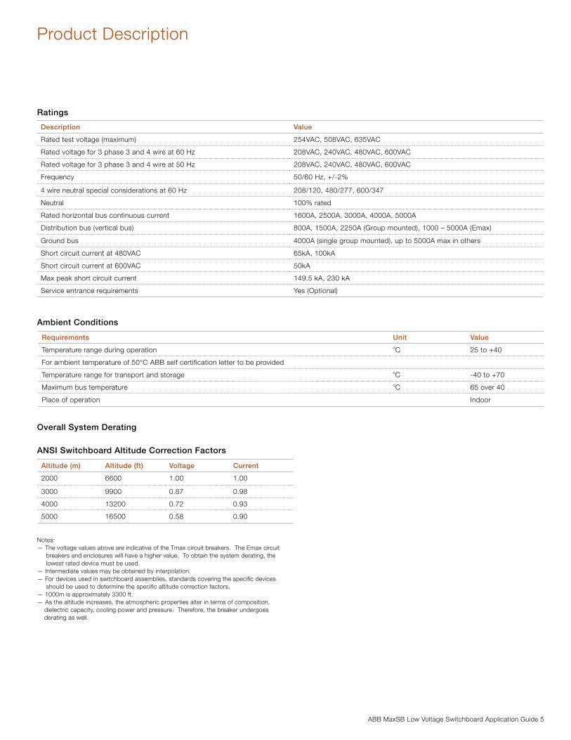
ABB MaxSB Low Voltage Switchboard Application Guide 5
Product Description
Ratings
Ambient Conditions
Overall System Derating
ANSI Switchboard Altitude Correction Factors
Notes:— The voltage values above are indicative of the Tmax circuit breakers. The Emax circuit breakers and enclosures will have a higher value. To obtain the system derating, the lowest rated device must be used. — Intermediate values may be obtained by interpolation.— For devices used in switchboard assemblies, standards covering the specific devices should be used to determine the specific altitude correction factors.— 1000m is approximately 3300 ft.— As the altitude increases, the atmospheric properties alter in terms of composition, dielectric capacity, cooling power and pressure. Therefore, the breaker undergoes derating as well.
Description Value
Rated test voltage (maximum) 254VAC, 508VAC, 635VAC
Rated voltage for 3 phase 3 and 4 wire at 60 Hz 208VAC, 240VAC, 480VAC, 600VAC
Rated voltage for 3 phase 3 and 4 wire at 50 Hz 208VAC, 240VAC, 480VAC, 600VAC
Frequency 50/60 Hz, +/-2%
4 wire neutral special considerations at 60 Hz 208/120, 480/277, 600/347
Neutral 100% rated
Rated horizontal bus continuous current 1600A, 2500A, 3000A, 4000A, 5000A
Distribution bus (vertical bus) 800A, 1500A, 2250A (Group mounted), 1000 – 5000A (Emax)
Ground bus 4000A (single group mounted), up to 5000A max in others
Short circuit current at 480VAC 65kA, 100kA
Short circuit current at 600VAC 50kA
Max peak short circuit current 149.5 kA, 230 kA
Service entrance requirements Yes (Optional)
Requirements Unit Value
Temperature range during operation oC 25 to +40
For ambient temperature of 50°C ABB self certification letter to be provided
Temperature range for transport and storage oC -40 to +70
Maximum bus temperature oC 65 over 40
Place of operation Indoor
Altitude (m) Altitude (ft) Voltage Current
2000 6600 1.00 1.00
3000 9900 0.87 0.98
4000 13200 0.72 0.93
5000 16500 0.58 0.90
6 ABB MaxSB Low Voltage Switchboard Application Guide
Product Description
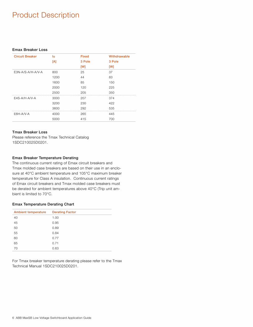
Emax Breaker Loss
Tmax Breaker LossPlease reference the Tmax Technical Catalog 1SDC210025D0201.
Emax Breaker Temperature DeratingThe continuous current rating of Emax circuit breakers and Tmax molded case breakers are based on their use in an enclo-sure at 40°C ambient temperature and 105°C maximum breaker temperature for Class A insulation. Continuous current ratings of Emax circuit breakers and Tmax molded case breakers must be derated for ambient temperatures above 40°C (Trip unit am-bient is limited to 70°C.
Emax Temperature Derating Chart
For Tmax breaker temperature derating please refer to the Tmax Technical Manual 1SDC210025D0201.
Circuit Breaker Iu
[A]
Fixed
3 Pole
[W]
Withdrawable
3 Pole
[W]
E3N-A/S-A/H-A/V-A 800
1200
1600
2000
2500
25
44
85
120
205
37
83
150
225
350
E4S-A/H-A/V-A 3000
3200
3600
207
230
292
374
422
535
E6H-A/V-A 4000
5000
265
415
445
700
Ambient temperature Derating Factor
40
45
50
55
60
65
70
1.00
0.95
0.89
0.84
0.77
0.71
0.63
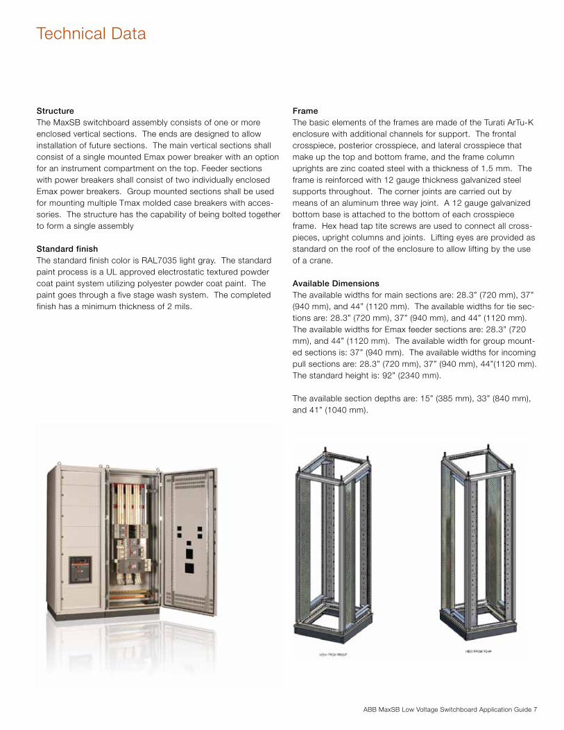
ABB MaxSB Low Voltage Switchboard Application Guide 7
Technical Data
StructureThe MaxSB switchboard assembly consists of one or more enclosed vertical sections. The ends are designed to allow installation of future sections. The main vertical sections shall consist of a single mounted Emax power breaker with an option for an instrument compartment on the top. Feeder sections with power breakers shall consist of two individually enclosed Emax power breakers. Group mounted sections shall be used for mounting multiple Tmax molded case breakers with acces-sories. The structure has the capability of being bolted together to form a single assembly
Standard finishThe standard finish color is RAL7035 light gray. The standard paint process is a UL approved electrostatic textured powder coat paint system utilizing polyester powder coat paint. The paint goes through a five stage wash system. The completed finish has a minimum thickness of 2 mils.
FrameThe basic elements of the frames are made of the Turati ArTu-K enclosure with additional channels for support. The frontal crosspiece, posterior crosspiece, and lateral crosspiece that make up the top and bottom frame, and the frame column uprights are zinc coated steel with a thickness of 1.5 mm. The frame is reinforced with 12 gauge thickness galvanized steel supports throughout. The corner joints are carried out by means of an aluminum three way joint. A 12 gauge galvanized bottom base is attached to the bottom of each crosspiece frame. Hex head tap tite screws are used to connect all cross-pieces, upright columns and joints. Lifting eyes are provided as standard on the roof of the enclosure to allow lifting by the use of a crane.
Available DimensionsThe available widths for main sections are: 28.3” (720 mm), 37” (940 mm), and 44” (1120 mm). The available widths for tie sec-tions are: 28.3” (720 mm), 37” (940 mm), and 44” (1120 mm). The available widths for Emax feeder sections are: 28.3” (720 mm), and 44” (1120 mm). The available width for group mount-ed sections is: 37” (940 mm). The available widths for incoming pull sections are: 28.3” (720 mm), 37” (940 mm), 44”(1120 mm). The standard height is: 92” (2340 mm).
The available section depths are: 15” (385 mm), 33” (840 mm), and 41” (1040 mm).
8 ABB MaxSB Low Voltage Switchboard Application Guide
Technical Data
Shipping designRemovable wood shipping base or pallet is provided per ship-ping split and anchored at four points. The switchboard maxi-mum shipping split is 78” (1990 mm).
Doors and coversSide panels and rear panels shall consist of a 1-piece design 1.5mm (.059”) thickness steel secured by M6 screws. Side panels and rear panels are provided in standard finish paint.
The MaxSB is provided with a single piece top cover for depths up to 41” (1040 mm) with slots along the side to allow for heat rise. The top panel is made of 14 gauge thickness steel.
Circuit breaker and equipment compartment doors are provided with a separate hinged door design and of 16 gauge thickness. All doors are secured by screws as a standard.
BarriersInstrument mounting panels are used for mounting electrical equipment and as barriers to isolate electrical components from the main bus when accessing through the front. Optional glastic or steel barriers are available between each section to segregate each section completely.
When service entrance is required, the MaxSB will incorporate all appropriate service entrance barriers.
ABB MaxSB Low Voltage Switchboard Application Guide 9
Technical Data
NameplatesMaxSB nameplates meet all standards listed in UL 891. Pre-cautionary labels meet ANSI Z52.4. Standard nameplates for devices are white background with black lettering phenolic screwed on type. Other optional nameplates are available upon request. The main system nameplate is stainless steel screwed on type with self tapping screws with engraved lettering.
The following information is available on switchboard assembly nameplates:
− Manufacturer’s name and address − Manufacturer’s type designations − Manufacturer’s identification reference − Rated maximum voltage (where applicable) − Rated power frequency (where applicable) − Rated continuous current (main bus) − Rated short-circuit withstand current − Date of manufacture
Instruction manual number
Enclosure The MaxSB switchboard enclosure is NEMA 1 rated. The enclosures are deadfront, metal-enclosed structures. All front doors, side panels, and rear panels are painted using electro-static powder type paint. The frame is not painted.
Standard Features: − RAL7035 paint color − Barriers between main breaker compartment and bus for
service entrance applications − Ground bus − Removable, steel top plates − Lifting eyes
Available Options: − Strip heaters and thermostats − Padlock provisions on main breaker − Optional paint colors − Metering − REA Arc Flash Relay (Group mounted only) − Maintenance Switch on Emax breakers − Mimic Bus − Nameplate
10 ABB MaxSB Low Voltage Switchboard Application Guide
Technical Data
Bus Bar SystemThe bus bar system is installed in the rear section of the switch-board and includes the main horizontal bus bar system, neutral bus when required, and vertical bus bars for feeder breaker sec-tions.
The main horizontal bus is arranged with phases A, B, C and neutral from top to bottom for top located bus and N, A, B, C for bottom located bus. The main bus can be mounted in the top, bottom, or middle of the section depending on the ap-plication. The bus bars are connected to the adjacent section at each end by means of shipping splices secured by grade 5 hardware. The size of the bus bar, number of bars per phase, and number and size of bolts depend upon the current rating of the bus. All bus designs are based on UL and ANSI 37.20.1 standard temperature rise of 65°C above maximum ambient air temperature of 40°C. All bus is supported by polyester standoff insulators on steel brackets.
Main bus amperages include: 1600A, 2500A, 3000A, 4000A, and 5000A with a bus bracing at 100kA. Non-insulated silver plated copper bussing is standard: optional tin plating copper is available.
All main horizontal bus construction is based on single section shipping splits.
The vertical bus bars run A, B, and C phase from the left to right when viewed from the front. The vertical bus riser is rated up to 2250A in the single group mounted sections with molded case breakers, or up to 3000 amps when fed from the main horizontal bus. The bus bracing is rated for 100kA. The vertical bus bar is silver plated as standard; optional tin plating is avail-able on request. Breakers are connected by means of copper bus straps. The vertical bus mounting slots allow the breakers to mount in any location along the bus.
The ground bus for the single group mounted section is rated as follows: 1 bar of 1/4” x 2”, rated at 4000A. For other sections the ground bus is 1 bar of 1/4” x 4” copper rated up to 5000A. As a standard, ABB offers a silver plated copper ground bus with an optional tin plating option. A 600kcmil – 2 AWG mechanical ground lug with NEMA 2 hole mounting pattern is installed on the ground bus in each section of the lineup. As an option, ABB may accommodate other mechanical lug sizes. Some limitations may apply.
ABB MaxSB Low Voltage Switchboard Application Guide 11
Technical Data
Incoming ConnectionsABB offers several options for incoming connections including: cable, bus duct, and close couple connections to transform-ers. For cable incoming requirements ABB can accommodate top or bottom lugs for amperages of 1600A, 2500A, 3000A, 4000A, and 5000A applications. ABB provides mechanical lugs as standard with an option for compression lugs. For bus duct connections, ABB requires a certified construction draw-ing at the approval stage in order to match bus riser to it. The actual bus flange must be provided to the factory at the release to manufacturing stage in order to ship with the equipment. In close coupling applications ABB offers a standard connection to ABB dry type transformers for all available bus amperages. Connection to oil filled ABB transformers requires a transition section with a minimum width of 28.3” section. For all non ABB transformer connections, ABB will need to provide a customized design transition section. All certified construction drawings of the existing transformer need to be provided at the time of the quotation request.
Incoming Auxiliary Sections Information
WiringWiring for power circuit breakers is done on terminal strips lo-cated above or below the breaker. All additional wiring is done in an instrument compartment.
As a standard, all control wiring is a minimum #14 AWG gray SIS. Control wiring will be terminated by means of wire fer-rules, ring terminals, or fork terminals. Potential transformers are provided with either #14 AWG SIS wire or optional #12 AWG SIS wire. Current transformer wire is either #14 AWG SIS wire or optional #10 AWG SIS wire. Control wire for a control power transformer up to 1kVA is #14 AWG SIS. For higher rated con-trol power transformers, the appropriate wire size is used.
Control wires are ran through openings covered with a grommet or other type of insulating material to prevent wire damage. Wire markers are not provided as a standard. Optional heat shrinkable wire markers can be provided.
Instrument compartments are available for mounting addi-tional devices such as, but not limited to: voltage transformers, control power transformers, metering, and supervisory devices. Internal compartments are also available for mounting terminal blocks for customer and internal wiring. Breaker devices such as indicating lights, control switches, and specified meters are either mounted in the main breaker compartment door or in an instrument compartment.
Spare terminal points can be located in front of the board in an instrument compartment or in the breaker compartment. Number of spare terminal points may impact overall equipment layout and dimensions.
Ampacity
(A)
Width Depth
(Fixed breakers
in line up)
Depth
(Drawout breakers
in line up)
800-2500 28.3” (720 mm) 33” (840 mm) 41” (1040 mm)
3000-3200 37” (940 mm) 33” (840 mm) 41” (1040 mm)
4000-5000 44”(1120 mm) 33” (840 mm) 41” (1040 mm)
12 ABB MaxSB Low Voltage Switchboard Application Guide
Instrumentation/Metering
Voltage Transformer – External Metering and RelayingThe MaxSB can provide voltage transformers when requested as an option. The voltage transformers are mounted in either an instrument compartment at the top or in a control compartment at the bottom of the section. The electrical characteristics of ABB’s standard potential transformer consist of the following:
Insulation Class is 600 volt dielectric, 10 kV full wave BIL. Ac-curacy Class is 0.6W and 1.2 X burdens at 60 Hz. Thermal ratings are 150 VA at 30°C ambient and 100 VA at 55°C ambi-ent. Primary and secondary fuses are mounted separately in an instrument compartment. Terminals are brass studs No. 10-32 with one lockwasher, flatwasher, and regular nut. Approximate weight is 7.75 lbs.
Control Power TransformerThe ABB MaxSB can be supplied with an optional control power transformer in order to provide 120VAC control power. The 120VAC control power transformer shall be sized accordingly for the load requirement of the breakers and other equipment. The MaxSB can also accommodate a 125VDC external source for the instruments and breakers as optional. The control power transformer shall be mounted in either an available instru-ment compartment or control compartment. The control power transformer shall have the same insulation class as the voltage transformers.
Primary and secondary fuses are mounted either separately in an instrument compartment or on board fuse clips mounted on the transformer. ABB control power transformers are available with the following ratings: 750VA, 1 kVA and 3 kVA. For control power transformers above 3 kVA, please consult factory.
Voltage Ratio Turns Ratio Rec. Primary Fuse
Rating
120:120 120:120 4.0
240:120 240:120 2.0
277:120 277:120 2.0
288:120 288:120 1.5
480:120 480:120 1.0
600:1 600:1 0.75
ABB MaxSB Low Voltage Switchboard Application Guide 13
Instrumentation/Metering
Current TransformersCurrent transformers utilized in MaxSB are mounted either on the line side or the load side of the main breaker. The electrical characteristics of ABB’s standard current transformers consist of the following:
600Volts, 10 kV BIL Frequency 50-400Hz
Zero Sequence Current Transformers and Ground Fault RelaysZero sequence current transformers can be offered as an option for sections with Emax breakers. The accuracy of the standard zero sequence CTs shall be a minimum of C50. Along with the zero sequence CT, an optional ABB Ground Fault Relay is available. If another ground fault relay is customer specified, the factory will need to be contacted. The minimum depth of the switchboard shall be 41” (1040 mm) when this option is selected.
MeteringThe MaxSB switchboard allows for mounting a variety of meter-ing options. The standard meter is the Electro Industries Shark 100 Multifunction Meter.
Basic Features Summary − Meets ANSI C12.20 − 0.2% Class Revenue Certifiable Energy and Demand Meter-
ing − Multifunction Measurement − Power quality measurements (%THD and Alarm limits) − 3 Line .56 inch LED display − % of Load Bar for Analog Meter Perception − Standard RS485 (Modbus and DNP 3.0) − Ethernet communication as optional − IrDA Port for PDA Read − Ultra Compact − Fits both ANSI and DIN Cutouts
Other Multifunction Meters are available upon request. Please contact the ABB factory for other types of meters.
Analog switchboard meters, such as ammeters, voltmeters, watthour, power factor, etc. are also available. As a standard, ABB will supply Crompton Series 77 for these types of devices. All metering devices are protected by means of ABB miniature breakers.
Ratio ANSI METERING CLASS AT 60HZ SECONDARY
WINDING
RESISTANCE
(OHMS @ 75°C)
BO.1 BO.2 BO.5 BO.9 B1.8
400:5 0.6 0.6 1.2 1.2 0.095
500:5 0.3 0.3 0.6 1.2 2.4 0.178
600:5 0.3 0.3 0.6 0.6 1.2 0.190
750:5 0.3 0.3 0.3 0.6 1.2 0.211
800:5 0.3 0.3 0.3 0.6 0.6 0.256
1000:5 0.3 0.3 0.3 0.3 0.6 0.368
1200:5 0.3 0.3 0.3 0.3 0.6 0.262
1500:5 0.3 0.3 0.3 0.6 0.6 0.328
1600:5 0.3 0.3 0.3 0.6 0.6 0.410
2000:5 0.3 0.3 0.3 0.3 0.6 0.347
3000:5 0.3 0.3 0.3 0.3 0.6 0.625
3200:5 0.3 0.3 0.3 0.3 0.6 0.536
4000:5 0.3 0.3 0.3 0.3 0.6 0.834
5000:5 0.3 0.3 0.3 0.3 0.6 0.872

1
64 5
32
14 ABB MaxSB Low Voltage Switchboard Application Guide
Breaker Control SwitchElectrically operated breakers can be provided with breaker control switches when required. The standard offering is the Electroswitch Series 20 breaker control switch. Optional name-plates with LEDs are available. Please see Layout section at the end of the document for restrictions.
Selector SwitchesABB can provide selector switches as an option. Selector switches are used for Auto/Manual transfer schemes or Local/Remote selection. An ABB type cam switch is used as a stan-dard. Optional switches can be provided upon request.
Test Switches and PlugsAs an option, the ABB MaxSB switchboard will allow the instal-lation of the ABB FT-1 or FT-14 test switch or test plugs. The test switch may be utilized for current and potential transformer testing. The make-before-break current short circuit feature allows quick and safe isolation for equipment from current transformer circuits. All Flexitest Switches meet or exceed all requirements of ANSI/IEEE Standard C37.90 and are UL, CUL and CSA listed. All Flexitest Switches are rated at 600 volts and 30 amps. As a standard, ABB offers the black cover test switch. The clear cover is available as an option.
Space Heaters, Thermostats, and HumidistatOne space heater per section mounted on the bottom frame piece is available as an option. Heaters are rated for 240VAC, 250W but are operated at 120VAC. The space heaters are enclosed in a metal protective housing. The thermostat utilized with space heaters has an operating range of 10 to 100 degrees Fahrenheit. The contact is a SPST design rated at 15 amps operating at 120/240VAC. A humidistat control is also available as an option.
Technical Data
TVSSThe MaxSB can provide devices as an option to help protect AC electrical circuits from the effect of lightning-induced cur-rents, substation switching transients, and internally generated transients resulting from inductive or capacitive load switching known as TVSS.
Features
− UL 1449 Third Edition Listed, cUL, UL 1283 R/C − UL 1449-3 Type 2 SPD − UL 1449-3 tested SCCR: 200kA − UL 1449-3 Voltage Protection Ratings (VPRs):
− 208Y/120V: as low as 500V − 480Y/277V: as low as 900V
− 200kAIR rated fusing − Less than 1 nanosecond response time − Repetitive Impulse: 5,000 hits − AC Sinewave Tracking Filter with EMI/RFI Filtering up to
-50dB from 10kHz to 100MHz − Designed, Manufactured & Tested consistent with:
− ANSI/IEEE C62.41.1-2002, C62.41.2-2002, and C62.45-2002
− NEMA LS-1 − NEC Article 285
− High Energy Parallel Design for Category C3 & C-High ap-plications
− Individually Fused Suppression Modes − Large-Block utility grade 34mm square MOVs − Replaceable Phase Module Construction − Thermal Sensitivity in Each Mode − Busbar Construction − Solid State Bidirectional Operation − Busbar connection
1. TVSS | 2. Breaker Control Switch | 3. Selector Switch | 4. Test Switches and Plugs | 5. & 6. Space Heaters, Thermostats, and Humidistats
ABB MaxSB Low Voltage Switchboard Application Guide 15
Section Types
Emax Main SectionsThe MaxSB provides main sections up to 5000A using fixed or drawout type Emax power circuit breakers (UL1066). Each cir-cuit breaker is located behind a hinged door secured by screws.
There are three available frame sizes that may be used in the MaxSB: E3, E4, and E6
The Emax power circuit breaker is available in various levels of interrupting ratings (AIR) as listed below.
Table 1: Emax Power Circuit Breaker Interrupting Rating
Amperage
(A)
Frame
Size
Dimensions Line/Load Lug Information
Width Depth Quantity
(per phase)
Size (kcmil)
Mechanical
800 E3 28.3”
(720mm)
33”
(840 mm)
2 #2-600
1200 3
1600 4
2000 5
2500 6
3000 E4 37”
(940 mm)
33”
(840 mm)
8
3200 8
4000 E6 44”
(1120 mm)
41”
(1040 mm)
10
5000 12
Frame Size Circuit
Breaker
Model
Rated Short Time
240V
[kA]
480V
[kA]
600V
[kA]
2000, 2500 E3 N-A 65 50 50
800,1200, 1600, 2000, 2500 E3 S-A 85 65 65
800,1200, 1600, 2000, 2500 E3 H-A 85 85 85
800,1200, 1600, 2000, 2500 E3 V-A 125 125 100
3200 E4 S-A 85 65 65
3200 E4 H-A 100 85 85
3200 E4 V-A 100 100 100
3200 E4 L-A 150 150 100
4000 E6 H-A 125 85 85
4000 E6 V-A 125 125 100
4000 E6 L-A 150 150 100
5000 E6 H-A 125 85 85
5000 E6 V-A 125 125 100
5000 E6 L-A 150 150 100
Available Accessories − Additional auxiliary contacts—up to 15 − TOC contacts – up to 10 − Spring charging motor − Shunt trip − Undervoltage release − Unvervoltage contact − Key interlock − Padlock attachment − Communications – Modbus standard − Mechanical counter − Transparent breaker cover − Bell Alarm − Bell Alarm reset − Button guard − Shutter padlock − Position key lock − Shutter position indicator − Kirk Key accessory − PR010/T portable test kit − Circuit breaker lift truck
16 ABB MaxSB Low Voltage Switchboard Application Guide
Section Types
Stacked Feeder SectionsThe MaxSB can provide stacked feeder sections up to 2000A using fixed or drawout type Emax power circuit breakers (UL1066). Each circuit breaker is located behind a hinged door secured by screws.
The MaxSB utilizes only the E3 frame size.
The Emax power circuit breaker is available in various levels of interrupting ratings (AIR) as listed below.
Stacked Emax Power Circuit Breaker Interrupting Rating
Amperage
(A)
Frame
Size
Dimensions Line/Load Lug Information
Width Depth Quantity
(per phase)
Size (kcmil)
Mechanical
800 E3 28.3”
(720mm)
33”
(840 mm)
2 #2-600
1200 3
1600 4
2000 5
Frame Size Circuit
Breaker
Model
Rated Short Time
240V
[kA]
480V
[kA]
600V
[kA]
800, 1200, 1600, 2000, 2500 E3 N-A 65 50 50
800,1200, 1600, 2000, 2500 E3 S-A 85 65 65
800,1200, 1600, 2000, 2500 E3 H-A 85 85 85
800,1200, 1600, 2000, 2500 E3 V-A 125 125 100
Available Accessories − Additional auxiliary contacts—up to 15 − TOC contacts – up to 10 − Spring charging motor − Shunt trip − Undervoltage release − Unvervoltage contact − Key interlock − Padlock attachment − Communications – Modbus standard − Mechanical counter − Transparent breaker cover − Bell Alarm − Bell Alarm reset − Button guard − Shutter padlock − Position key lock − Shutter position indicator − Kirk Key accessor − PR010/T portable test kit − Circuit breaker lift truck
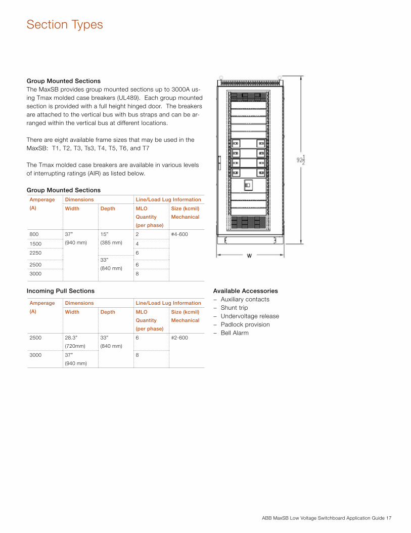
ABB MaxSB Low Voltage Switchboard Application Guide 17
Group Mounted SectionsThe MaxSB provides group mounted sections up to 3000A us-ing Tmax molded case breakers (UL489). Each group mounted section is provided with a full height hinged door. The breakers are attached to the vertical bus with bus straps and can be ar-ranged within the vertical bus at different locations.
There are eight available frame sizes that may be used in the MaxSB: T1, T2, T3, Ts3, T4, T5, T6, and T7
The Tmax molded case breakers are available in various levels of interrupting ratings (AIR) as listed below.
Group Mounted Sections
Incoming Pull Sections
Section Types
Amperage
(A)
Dimensions Line/Load Lug Information
Width Depth MLO
Quantity
(per phase)
Size (kcmil)
Mechanical
800 37”
(940 mm)
15”
(385 mm)
2 #4-600
1500 4
2250 633”
(840 mm)2500 6
3000 8
Available Accessories − Auxiliary contacts − Shunt trip − Undervoltage release − Padlock provision − Bell Alarm
Amperage
(A)
Dimensions Line/Load Lug Information
Width Depth MLO
Quantity
(per phase)
Size (kcmil)
Mechanical
2500 28.3”
(720mm)
33”
(840 mm)
6 #2-600
3000 37”
(940 mm)
8
18 ABB MaxSB Low Voltage Switchboard Application Guide
Emax Breaker
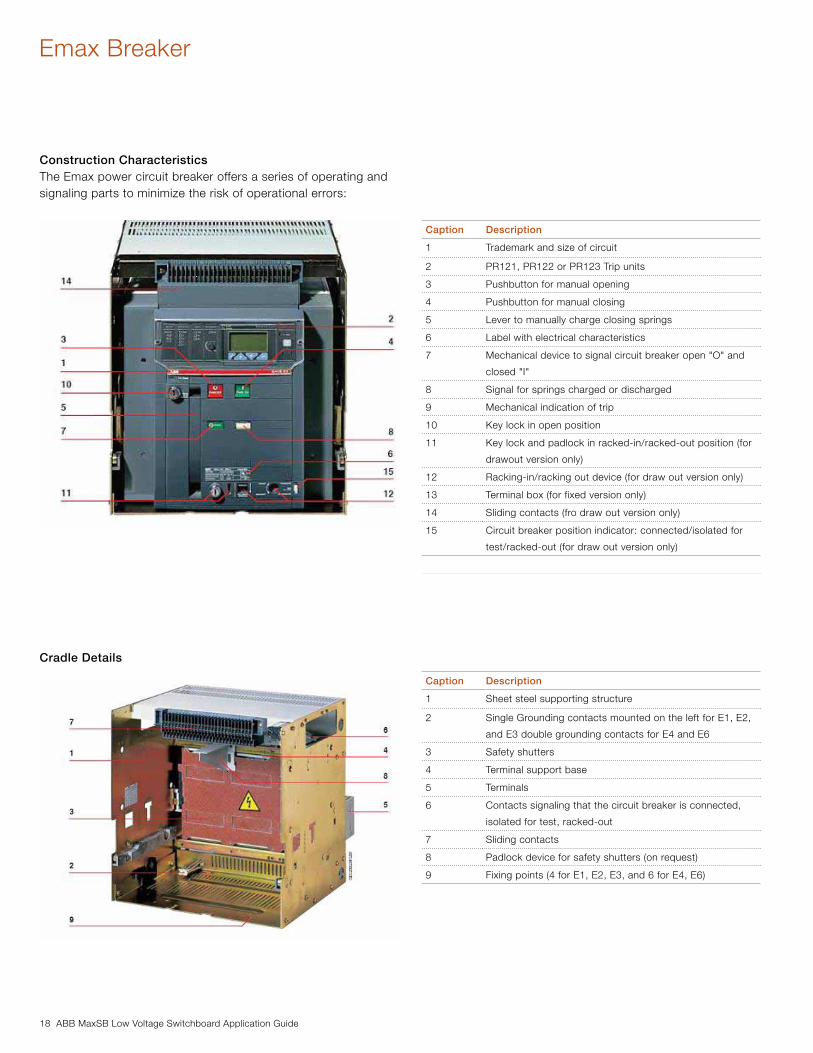
Construction CharacteristicsThe Emax power circuit breaker offers a series of operating and signaling parts to minimize the risk of operational errors:
Cradle Details
Caption Description
1 Trademark and size of circuit
2 PR121, PR122 or PR123 Trip units
3 Pushbutton for manual opening
4 Pushbutton for manual closing
5 Lever to manually charge closing springs
6 Label with electrical characteristics
7 Mechanical device to signal circuit breaker open "O" and
closed "I"
8 Signal for springs charged or discharged
9 Mechanical indication of trip
10 Key lock in open position
11 Key lock and padlock in racked-in/racked-out position (for
drawout version only)
12 Racking-in/racking out device (for draw out version only)
13 Terminal box (for fixed version only)
14 Sliding contacts (fro draw out version only)
15 Circuit breaker position indicator: connected/isolated for
test/racked-out (for draw out version only)
Caption Description
1 Sheet steel supporting structure
2 Single Grounding contacts mounted on the left for E1, E2,
and E3 double grounding contacts for E4 and E6
3 Safety shutters
4 Terminal support base
5 Terminals
6 Contacts signaling that the circuit breaker is connected,
isolated for test, racked-out
7 Sliding contacts
8 Padlock device for safety shutters (on request)
9 Fixing points (4 for E1, E2, E3, and 6 for E4, E6)
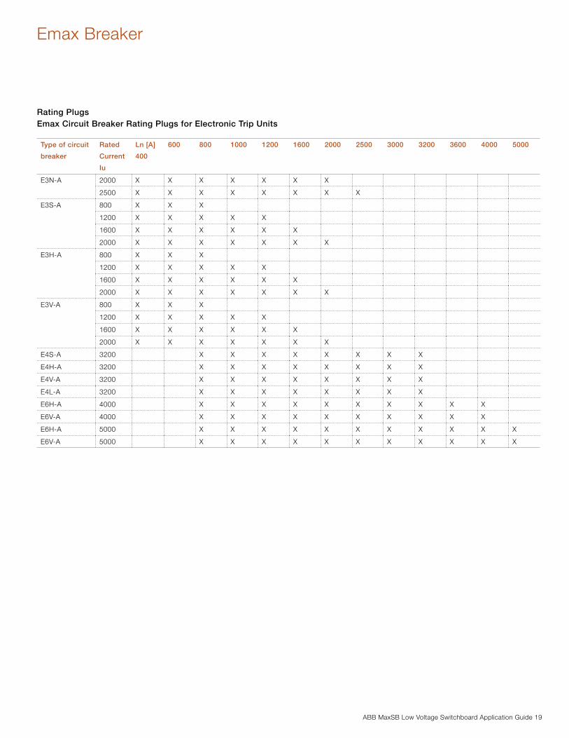
ABB MaxSB Low Voltage Switchboard Application Guide 19
Emax Breaker
Rating PlugsEmax Circuit Breaker Rating Plugs for Electronic Trip Units
Type of circuit
breaker
Rated
Current
Iu
Ln [A]
400
600 800 1000 1200 1600 2000 2500 3000 3200 3600 4000 5000
E3N-A 2000 X X X X X X X
2500 X X X X X X X X
E3S-A 800 X X X
1200 X X X X X
1600 X X X X X X
2000 X X X X X X X
E3H-A 800 X X X
1200 X X X X X
1600 X X X X X X
2000 X X X X X X X
E3V-A 800 X X X
1200 X X X X X
1600 X X X X X X
2000 X X X X X X X
E4S-A 3200 X X X X X X X X
E4H-A 3200 X X X X X X X X
E4V-A 3200 X X X X X X X X
E4L-A 3200 X X X X X X X X
E6H-A 4000 X X X X X X X X X X
E6V-A 4000 X X X X X X X X X X
E6H-A 5000 X X X X X X X X X X X
E6V-A 5000 X X X X X X X X X X X
20 ABB MaxSB Low Voltage Switchboard Application Guide
Emax Breaker
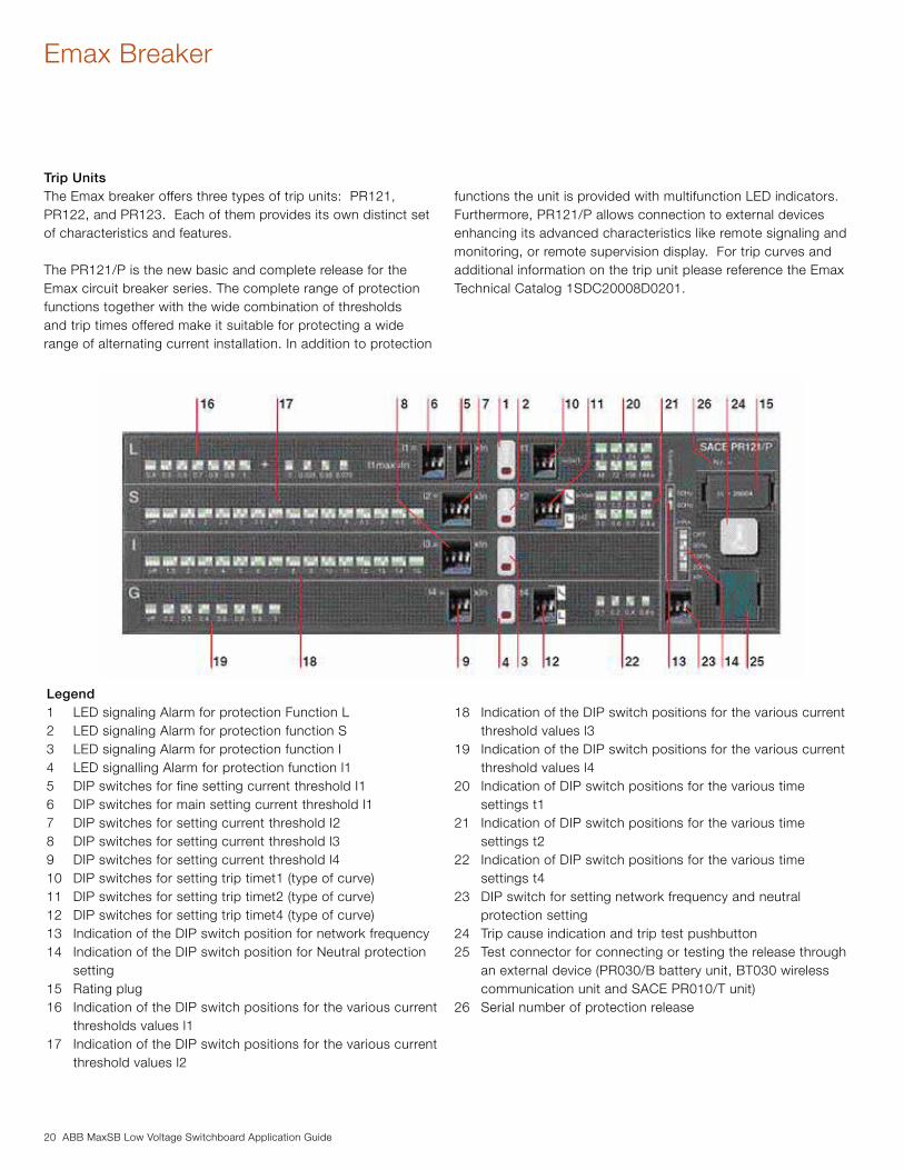
Trip UnitsThe Emax breaker offers three types of trip units: PR121, PR122, and PR123. Each of them provides its own distinct set of characteristics and features.
The PR121/P is the new basic and complete release for the Emax circuit breaker series. The complete range of protection functions together with the wide combination of thresholds and trip times offered make it suitable for protecting a wide range of alternating current installation. In addition to protection
functions the unit is provided with multifunction LED indicators. Furthermore, PR121/P allows connection to external devices enhancing its advanced characteristics like remote signaling and monitoring, or remote supervision display. For trip curves and additional information on the trip unit please reference the Emax Technical Catalog 1SDC20008D0201.
Legend1 LED signaling Alarm for protection Function L2 LED signaling Alarm for protection function S3 LED signaling Alarm for protection function I4 LED signalling Alarm for protection function l15 DIP switches for fine setting current threshold I16 DIP switches for main setting current threshold l17 DIP switches for setting current threshold I28 DIP switches for setting current threshold l39 DIP switches for setting current threshold l4 10 DIP switches for setting trip timet1 (type of curve)11 DIP switches for setting trip timet2 (type of curve)12 DIP switches for setting trip timet4 (type of curve)13 Indication of the DIP switch position for network frequency14 Indication of the DIP switch position for Neutral protection
setting15 Rating plug16 Indication of the DIP switch positions for the various current
thresholds values l117 Indication of the DIP switch positions for the various current
threshold values l2
18 Indication of the DIP switch positions for the various current threshold values l3
19 Indication of the DIP switch positions for the various current threshold values l4
20 Indication of DIP switch positions for the various time settings t1
21 Indication of DIP switch positions for the various time settings t2
22 Indication of DIP switch positions for the various time settings t4
23 DIP switch for setting network frequency and neutral protection setting
24 Trip cause indication and trip test pushbutton25 Test connector for connecting or testing the release through
an external device (PR030/B battery unit, BT030 wireless communication unit and SACE PR010/T unit)
26 Serial number of protection release
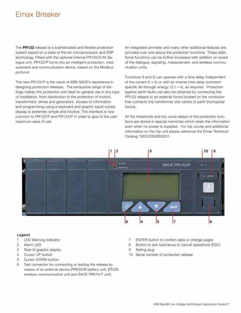
ABB MaxSB Low Voltage Switchboard Application Guide 21
Emax Breaker
The PR122 release is a sophisticated and flexible protection system based on a state-of the art microprocessor and DSP technology. Fitted with the optional internal PR120/D-M dia-logue unit, PR122/P turns into an intelligent protection, mea-surement and communication device, based on the Modbus protocol.
The new PR122/P is the result of ABB SACE’s experience in designing protection releases. The exhaustive range of set-tings makes this protection unit ideal for general use in any type of installation, from distribution to the protection of motors, transformers, drives and generators. Access to information and programming using a keyboard and graphic liquid crystal display is extremely simple and intuitive. The interface is now common to PR122/P and PR123/P in order to give to the user maximum ease of use.
An integrated ammeter and many other additional features are provided over and above the protection functions. These addi-tional functions can be further increased with addition on board of the dialogue, signaling, measurement, and wireless commu-nication units.
Functions S and G can operate with a time delay independent of the current (t = k) or with an inverse time delay (constant specific let-through energy: I2 t = k), as required. Protection against earth faults can also be obtained by connecting the PR122 release to an external toroid located on the conductor that connects the transformer star centre to earth (homopolar toroid).
All the thresholds and trip curve delays of the protection func-tions are stored in special memories which retain the information even when no power is supplied. For trip curves and additional information on the trip unit please reference the Emax Technical Catalog 1SDC20008D0201.
Legend1 LED Warning indicator2 Alarm LED3 Rear-lit graphic display4 Cursor UP button 5 Cursor DOWN button6 Test connector for connecting or testing the release by
means of an external device (PR030/B battery unit, BT030 wireless communication unit and SACE PR010/T unit)
7 ENTER button to confirm data or change pages8 Button to exit submenus or cancel operations (ESC)9 Rating plug10 Serial number of protection release

22 ABB MaxSB Low Voltage Switchboard Application Guide
The PR123 protection release completes the range of releases available for the Emax family of circuit breakers. It is a high-performance and extraordinarily versatile release, capable of offering a complete set of functions for protection, measure-ment, signaling, data storage and control of the circuit breaker, and it represents the benchmark in low voltage protection units for circuit breakers.
The front interface of the unit, common to PR122/P, is extremely simple thanks to the aid of the liquid crystal graphics display. It can show diagrams, bar graphs, measurements and sine curves for the various electrical values.
PR123 integrates all the features offered by PR122/P plus a se-ries of evolute functionalities. As with PR122, it can be integrat-ed with the additional features provided by internal modules and external accessories. For trip curves and additional information on the trip unit please reference the Emax Technical Catalog 1SDC20008D0201.
Legend1 LED Warning indicator2 Alarm LED3 Rear-lit graphic display4 Cursor UP button 5 Cursor DOWN button6 Test connector for connecting or testing the release by
means of an external device (PR030/B battery unit, BT030 wireless communication unit and SACE PR010/T unit)
7 ENTER button to confirm data or change pages8 Button to exit submenus or cancel operations (ESC)9 Rating plug10 Serial number of protection release11 PowerLED12 Voltage-uptake switch-disconnector
Emax Breaker
ABB MaxSB Low Voltage Switchboard Application Guide 23
Emax Breaker

24 ABB MaxSB Low Voltage Switchboard Application Guide
Emax Breaker
Trip Unit Modules PR122 and PR123 can be enriched with additional internal modules, increasing the capacity of the trip unit and making these units highly versatile.
Electrical signaling contacts: PR120/K Module
This unit, internally connected to PR122/P and PR123/P, allows the remote signaling of alarms and trips of the circuit breaker.Four independent power relays provided on the PR120/K mod-ule enable electrical signaling of the following:
− timing for protections L, S, G (and UV, OV, RV, RP, D, U, OF, UF where applicable);
− protections L, S, I, G, OT, (and UV, OV, RV, RP, D, U, OF, UF where applicable) tripped and other events;
− in addition, by using an external device (PR010/T, BT030, PR120/D-BT), the contacts can be freely configured in as-sociation with any possible event or alarm.
PR120/K can also be used as actuator for the Load control function.
In addition, the unit can be provided with a digital input signal, enabling the following functions:
− activation of alternative set of parameter (PR123/P only); − external trip command − trip reset of the trip unit − reset of PR120/K power relays
When the digital input is required the power relays have a com-mon connection.
This latest kind of connection must be specified in the order when required together with the circuit breaker. When PR120/K is ordered as loose accessory both of the configurations are possible.
The auxiliary 24V DC power supply is needed for the unit (shown by a green Power LED). Four yellow LEDs show the status of each output relay.
The use of Voltage Transformers is mandatory for rated voltages higher than 690V.
Type Monostable STDP
Maximum switching power (resisti-
ve load)
100W / 1250 VA
Maximum switching voltage 130 V DC / 250 V AC
Maximum switching current 5A
Breaking capacity (resistive load)
@ 30V DC
@ 250V AC
3.3A
5A
Contact/coil insulation 200 V eff (1 min @ 50 Hz)

ABB MaxSB Low Voltage Switchboard Application Guide 25
Emax Breaker
PR120/V Measurement ModuleThis optional internal module, installed in PR122 (standard in PR123), allows the release to measure the phase and neutral voltages and to process them in order to achieve a series of features, in terms of protection and measurement.
PR120/V does not normally require any external connection or Voltage Transformer, since it is connected internally to the lower terminals of Emax Circuit Breakers. When necessary, the connection of voltage pick-ups can be moved to any other points (i.e. upper terminals), by using the alternative connection located in the terminal box. The module is provided with a seal-able switch-disconnector for the dielectric test. PR120/V is able to energize the PR122 while line voltage input is above 85V. The use of Voltage Transformers is mandatory for rated voltages higher than 690V. Voltage transformers shall have burdens equal to 10VA and accuracy class 0.5 or better.
Additional Protections with PR120/V: − UnderVoltage (UV) protection − Overvoltage (OV) protection − Residual voltage (RV) protection − Reverse power (RP) protection − Underfrequency (UF) protection − Overfrequency (OF) protection − Phase sequence (alarm only)
All the above indicated protections can be excluded, although it is possible to leave only the alarm active when required.With the circuit breaker closed, these protections also oper-ate when the release is self-supplied. With the circuit breaker open, they operate when the auxiliary power supply (24V DC or PR120/V) is present: in this case the release will indicate the “ALARM” status.
Voltage protections UV, OV, RVWith the PR120/V module, the PR122/P release is able to pro-vide the undervoltage and overvoltage protection (UV, OV) and the residual voltage protection (RV). The residual voltage protec-tion RV identifies interruptions of the neutral (or of the earthing conductor in systems with earthed neutral) and faults that shift the star center in systems with insulated neutral (e.g. large earth faults). The star center shift is calculated as a vectorial sum of the phase voltages.
Reverse power protection RPReverse power protection is especially suitable for protecting large machines such as motors and generators. The PR122 with the PR120/V module can analyze the direction of the active power and open the circuit breaker if the direction is opposite to that of normal operation. The reverse power threshold and the trip time are adjustable.
Frequency protections UF, OFThe frequency protections detect the variation of network frequency above adjustable thresholds, generating an alarm or opening the circuit breaker. It is a protection typically needed in an isolated network, i.e. powered by a genset.
26 ABB MaxSB Low Voltage Switchboard Application Guide
Emax Breaker
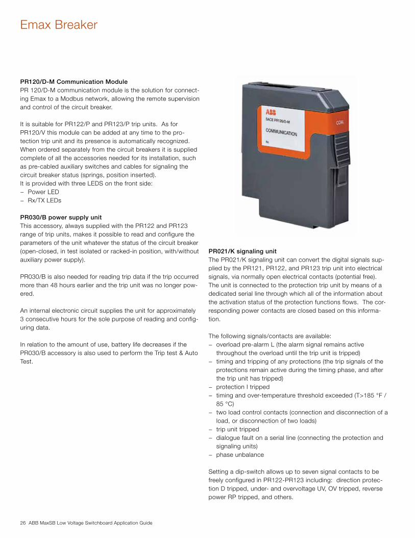
PR120/D-M Communication ModulePR 120/D-M communication module is the solution for connect-ing Emax to a Modbus network, allowing the remote supervision and control of the circuit breaker.
It is suitable for PR122/P and PR123/P trip units. As for PR120/V this module can be added at any time to the pro-tection trip unit and its presence is automatically recognized. When ordered separately from the circuit breakers it is supplied complete of all the accessories needed for its installation, such as pre-cabled auxiliary switches and cables for signaling the circuit breaker status (springs, position inserted). It is provided with three LEDS on the front side:
− Power LED − Rx/TX LEDs
PR030/B power supply unitThis accessory, always supplied with the PR122 and PR123 range of trip units, makes it possible to read and configure the parameters of the unit whatever the status of the circuit breaker (open-closed, in test isolated or racked-in position, with/without auxiliary power supply).
PR030/B is also needed for reading trip data if the trip occurred more than 48 hours earlier and the trip unit was no longer pow-ered.
An internal electronic circuit supplies the unit for approximately 3 consecutive hours for the sole purpose of reading and config-uring data.
In relation to the amount of use, battery life decreases if the PR030/B accessory is also used to perform the Trip test & Auto Test.
PR021/K signaling unitThe PR021/K signaling unit can convert the digital signals sup-plied by the PR121, PR122, and PR123 trip unit into electrical signals, via normally open electrical contacts (potential free). The unit is connected to the protection trip unit by means of a dedicated serial line through which all of the information about the activation status of the protection functions flows. The cor-responding power contacts are closed based on this informa-tion.
The following signals/contacts are available: − overload pre-alarm L (the alarm signal remains active
throughout the overload until the trip unit is tripped) − timing and tripping of any protections (the trip signals of the
protections remain active during the timing phase, and after the trip unit has tripped)
− protection I tripped − timing and over-temperature threshold exceeded (T>185 °F /
85 °C) − two load control contacts (connection and disconnection of a
load, or disconnection of two loads) − trip unit tripped − dialogue fault on a serial line (connecting the protection and
signaling units) − phase unbalance
Setting a dip-switch allows up to seven signal contacts to be freely configured in PR122-PR123 including: direction protec-tion D tripped, under- and overvoltage UV, OV tripped, reverse power RP tripped, and others.

ABB MaxSB Low Voltage Switchboard Application Guide 27
Emax Breaker
Type Monostable STDP
Maximum switching power (resisti-
ve load)
100W / 1250 VA
Maximum switching voltage 130 V DC / 250 V AC
Maximum switching current 5A
Breaking capacity (resistive load)
@ 30V DC
@ 250V AC
3.3A
5A
Contact/coil insulation 200 V eff (1 min @ 50 Hz)
Auxiliary power supply 24 V DC +/-20%
Maximum ripple 5%
Rated power @ 24V 4.4W
Two contacts available on the PR021/K unit (load control) can pilot a circuit breaker shunt trip and closing coil. These contacts allow various applications, including load control, alarms, signals and electrical locks.
Pressing the Reset pushbutton resets the status of all signals.The unit also contains ten LEDs to visually signal the following information:
− “Power ON”: auxiliary power supply present − “TX (Int Bus)”: flashing synchronized with dialogue with
the Internal Bus − Eight LEDs associated with the signaling contacts.
The following table lists the characteristics of the signaling contacts available in the PR021/K unit.
28 ABB MaxSB Low Voltage Switchboard Application Guide
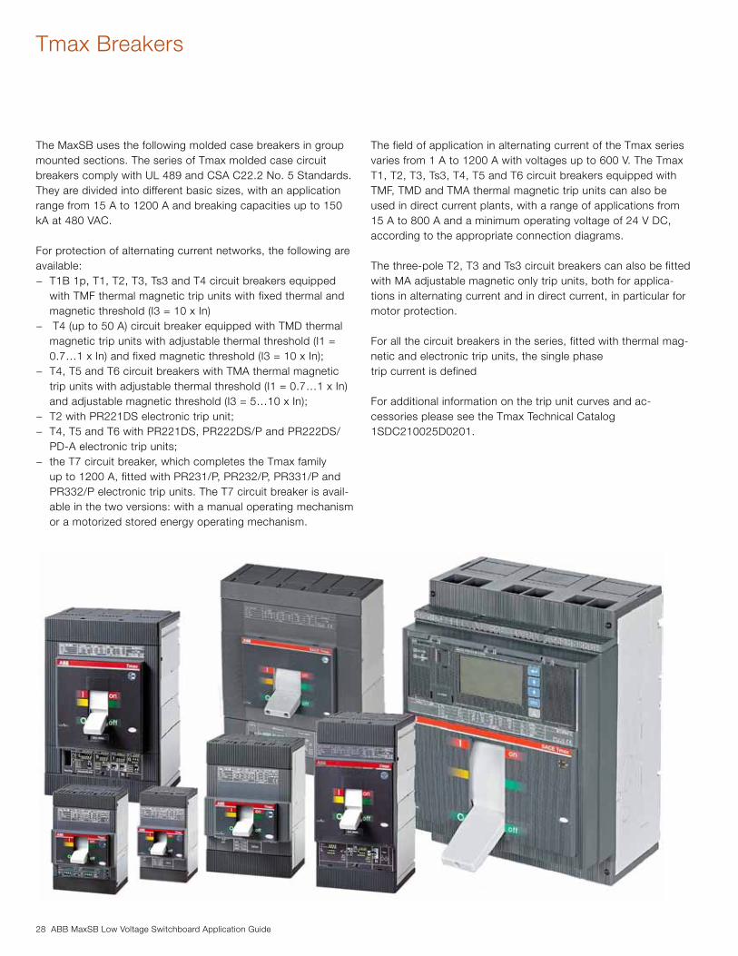
Tmax Breakers
The MaxSB uses the following molded case breakers in group mounted sections. The series of Tmax molded case circuit breakers comply with UL 489 and CSA C22.2 No. 5 Standards. They are divided into different basic sizes, with an application range from 15 A to 1200 A and breaking capacities up to 150 kA at 480 VAC.
For protection of alternating current networks, the following are available:
− T1B 1p, T1, T2, T3, Ts3 and T4 circuit breakers equipped with TMF thermal magnetic trip units with fixed thermal and magnetic threshold (I3 = 10 x In)
− T4 (up to 50 A) circuit breaker equipped with TMD thermal magnetic trip units with adjustable thermal threshold (I1 = 0.7…1 x In) and fixed magnetic threshold (I3 = 10 x In);
− T4, T5 and T6 circuit breakers with TMA thermal magnetic trip units with adjustable thermal threshold (I1 = 0.7…1 x In) and adjustable magnetic threshold (I3 = 5…10 x In);
− T2 with PR221DS electronic trip unit; − T4, T5 and T6 with PR221DS, PR222DS/P and PR222DS/
PD-A electronic trip units; − the T7 circuit breaker, which completes the Tmax family
up to 1200 A, fitted with PR231/P, PR232/P, PR331/P and PR332/P electronic trip units. The T7 circuit breaker is avail-able in the two versions: with a manual operating mechanism or a motorized stored energy operating mechanism.
The field of application in alternating current of the Tmax series varies from 1 A to 1200 A with voltages up to 600 V. The Tmax T1, T2, T3, Ts3, T4, T5 and T6 circuit breakers equipped with TMF, TMD and TMA thermal magnetic trip units can also be used in direct current plants, with a range of applications from 15 A to 800 A and a minimum operating voltage of 24 V DC, according to the appropriate connection diagrams.
The three-pole T2, T3 and Ts3 circuit breakers can also be fitted with MA adjustable magnetic only trip units, both for applica-tions in alternating current and in direct current, in particular for motor protection.
For all the circuit breakers in the series, fitted with thermal mag-netic and electronic trip units, the single phasetrip current is defined
For additional information on the trip unit curves and ac-cessories please see the Tmax Technical Catalog 1SDC210025D0201.
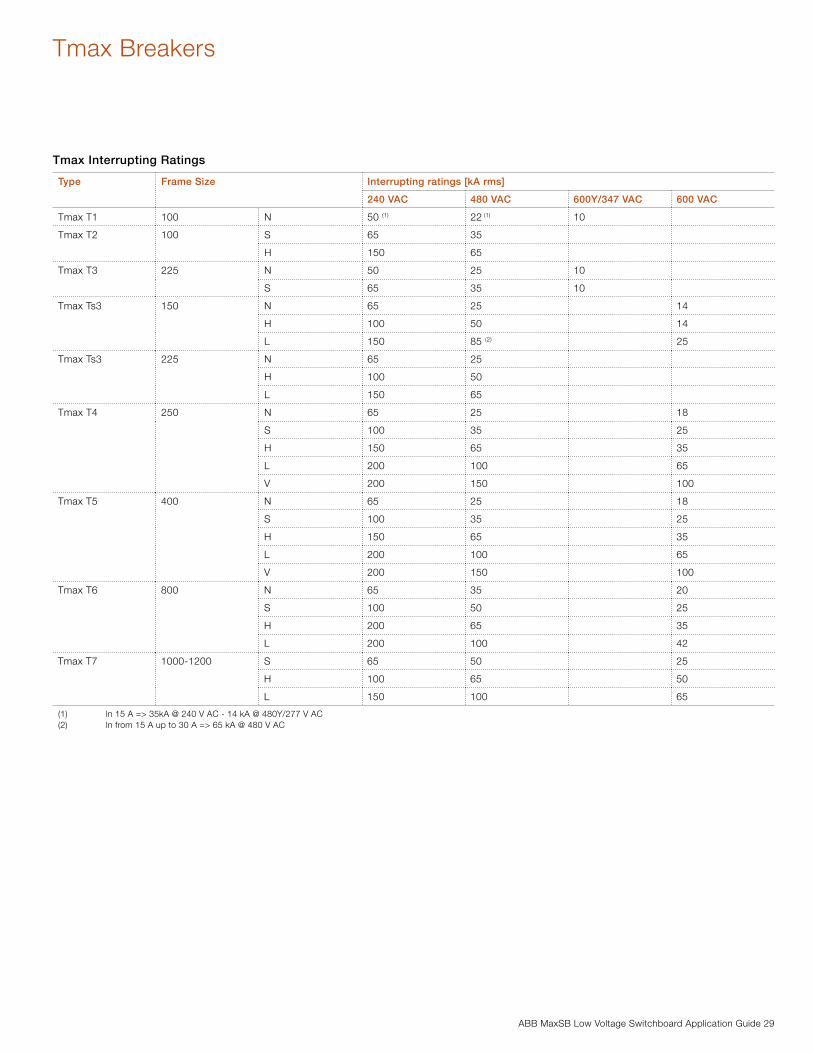
ABB MaxSB Low Voltage Switchboard Application Guide 29
Tmax Breakers
Tmax Interrupting Ratings
Type Frame Size Interrupting ratings [kA rms]
240 VAC 480 VAC 600Y/347 VAC 600 VAC
Tmax T1 100 N 50 (1) 22 (1) 10
Tmax T2 100 S 65 35
H 150 65
Tmax T3 225 N 50 25 10
S 65 35 10
Tmax Ts3 150 N 65 25 14
H 100 50 14
L 150 85 (2) 25
Tmax Ts3 225 N 65 25
H 100 50
L 150 65
Tmax T4 250 N 65 25 18
S 100 35 25
H 150 65 35
L 200 100 65
V 200 150 100
Tmax T5 400 N 65 25 18
S 100 35 25
H 150 65 35
L 200 100 65
V 200 150 100
Tmax T6 800 N 65 35 20
S 100 50 25
H 200 65 35
L 200 100 42
Tmax T7 1000-1200 S 65 50 25
H 100 65 50
L 150 100 65
(1) ln 15 A => 35kA @ 240 V AC - 14 kA @ 480Y/277 V AC(2) ln from 15 A up to 30 A => 65 kA @ 480 V AC

30 ABB MaxSB Low Voltage Switchboard Application Guide
Tmax Breakers
Tmax Breaker Trip UnitsPR221DS − Tmax T2, T4, T5 and T6The PR221DS trip unit, available for T2,T4, T5 and T6, pro-vides protection functions against overload L and short-circuit S/I (version PR221DS-LS/I): with this version you can choose whether to have inverse time-delay S or instantaneous I protec-tion against short-circuit by moving the dedicated dip-switch. Alternatively, the version with only the protection function against instantaneous short-circuit I is available (version PR221DS-I).
There is a single adjustment for the phases and the neutral. The neutral is adjustable from 50 - 100% of the phases for Tmax T2 In = 160 A (T2 In<160 A, N = 100%), whereas for T4, T5 and T6 it is possible to select the protection threshold OFF, 50%
or 100% directly from the front of the trip unit by means of the specific dip switch.
The trip coil is always supplied with the PR221DS trip unit for Tmax T2 and is housed in the right-hand slot of the circuit breaker. Dedicated auxiliary contacts are available for T2 with electronic trip units.
For Tmax T4, T5 and T6, the opening solenoid is housed inter-nally and therefore, by not using the right hand slot of the circuit breaker, all the auxiliary contacts available can be used.
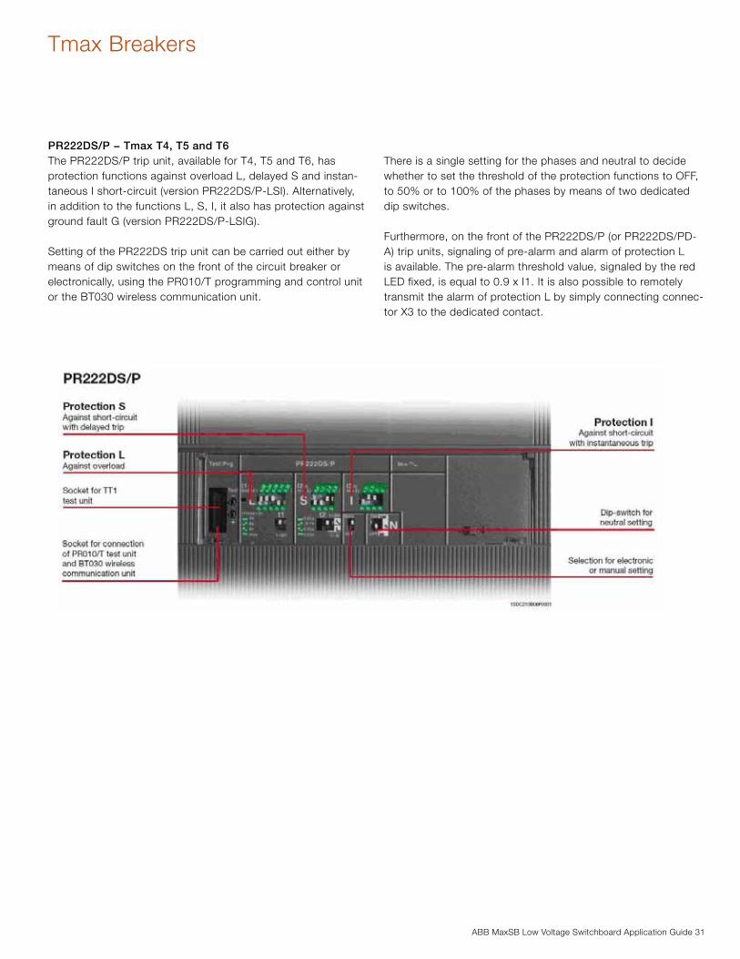
ABB MaxSB Low Voltage Switchboard Application Guide 31
Tmax Breakers
PR222DS/P − Tmax T4, T5 and T6The PR222DS/P trip unit, available for T4, T5 and T6, has protection functions against overload L, delayed S and instan-taneous I short-circuit (version PR222DS/P-LSI). Alternatively, in addition to the functions L, S, I, it also has protection against ground fault G (version PR222DS/P-LSIG).
Setting of the PR222DS trip unit can be carried out either by means of dip switches on the front of the circuit breaker or electronically, using the PR010/T programming and control unit or the BT030 wireless communication unit.
There is a single setting for the phases and neutral to decide whether to set the threshold of the protection functions to OFF, to 50% or to 100% of the phases by means of two dedicated dip switches.
Furthermore, on the front of the PR222DS/P (or PR222DS/PD-A) trip units, signaling of pre-alarm and alarm of protection L is available. The pre-alarm threshold value, signaled by the red LED fixed, is equal to 0.9 x I1. It is also possible to remotely transmit the alarm of protection L by simply connecting connec-tor X3 to the dedicated contact.
32 ABB MaxSB Low Voltage Switchboard Application Guide
Tmax Breakers
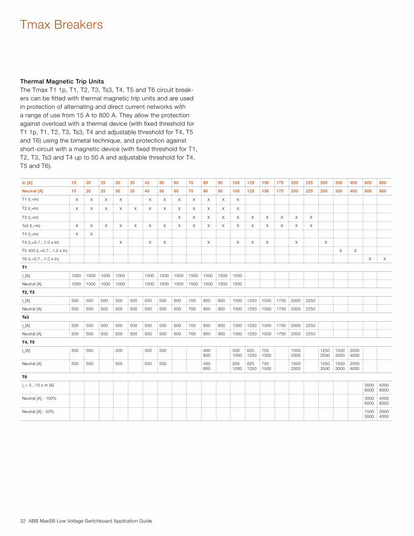
Thermal Magnetic Trip UnitsThe Tmax T1 1p, T1, T2, T3, Ts3, T4, T5 and T6 circuit break-ers can be fitted with thermal magnetic trip units and are used in protection of alternating and direct current networks with a range of use from 15 A to 800 A. They allow the protection against overload with a thermal device (with fixed threshold for T1 1p, T1, T2, T3, Ts3, T4 and adjustable threshold for T4, T5 and T6) using the bimetal technique, and protection against short-circuit with a magnetic device (with fixed threshold for T1, T2, T3, Ts3 and T4 up to 50 A and adjustable threshold for T4, T5 and T6).
In [A] 15 20 25 30 35 40 50 60 70 80 90 100 125 150 175 200 225 250 300 400 600 800
Neutral [A] 15 20 25 30 35 40 50 60 70 80 90 100 125 150 175 200 225 250 300 400 600 800
T1 (I1=In) X X X X X X X X X X X
T2 (I1=In) X X X X X X X X X X X X
T3 (I1=In) X X X X X X X X X X
Ts3 (I1=In) X X X X X X X X X X X X X X X X X
T4 (I1=In) X X
T4 (I1=0.7...1.0 x In) X X X X X X X X X
T5 400 (I1=0.7...1.0 x In) X X
T6 (I1=0.7...1.0 x In) X X
T1
I3 [A] 1000 1000 1000 1000 1000 1500 1500 1500 1500 1500 1500
Neutral [A] 1000 1000 1000 1000 1000 1500 1500 1500 1500 1500 1500
T2, T3
I3 [A] 500 500 500 500 500 500 500 600 700 800 900 1000 1250 1500 1750 2000 2250
Neutral [A] 500 500 500 500 500 500 500 600 700 800 900 1000 1250 1500 1750 2000 2250
Ts3
I3 [A] 500 500 500 500 500 500 500 600 700 800 900 1000 1250 1500 1750 2000 2250
Neutral [A] 500 500 500 500 500 500 500 600 700 800 900 1000 1250 1500 1750 2000 2250
T4, T5
I3 [A] 500 500 500 500 500 400800
5001000
6251250
7501500
10002000
12502500
15003000
20004000
Neutral [A] 500 500 500 500 500 400800
5001000
6251250
7501500
10002000
12502500
15003000
20004000
T6
I3 = 5...10 x In [A] 30006000
40008000
Neutral [A] - 100% 30006000
40008000
Neutral [A] - 50% 15003000
20004000
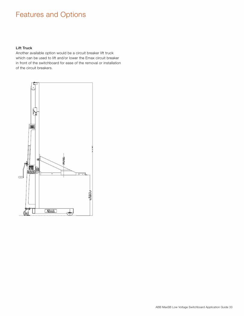
ABB MaxSB Low Voltage Switchboard Application Guide 33
Features and Options
Lift TruckAnother available option would be a circuit breaker lift truck which can be used to lift and/or lower the Emax circuit breaker in front of the switchboard for ease of the removal or installation of the circuit breakers.
34 ABB MaxSB Low Voltage Switchboard Application Guide
Features and Options
Configuration Test UnitAs an option ABB can provide a portable test unit for the Emax circuit breaker trip units. The PR010/T unit is an instrument ca-pable of performing the functions of secondary injection testing, programming, and reading parameters for the trip units equip-ping Emax low voltage air circuit breakers. In particular, the test function involves the following units:
− PR121P (all versions) − PR122P (all versions) − PR123P (all versions)
whereas the parameter programming and reading functions regard the range of PR122 and PR123 trip units.
All of the functions mentioned can be carried out “on board” by connecting the SACE PR010/T unit to the front multi-pin connector on the various protection units. Special interfacing cables supplied with the unit must be used for this connection.The human-machine interface takes the form of a touchpad and multi-line alphanumeric display.
The unit also has two LEDs to indicate, respectively: − POWER-ON and STAND BY − battery charge state
Two different types of test are available: automatic (for PR121, PR122, and PR123) and manual.
By connection to a PC (using the floppy-disc supplied by ABB), it is also possible to upgrade the software of the PR010/T unit and adapt the test unit to the development of new products.
It is also possible to store the most important results in the unit itself, and to send a report to the personal computer with fol-lowing information:
− type of protection tested − threshold selected − curve selected − phase tested − test current − estimated trip time − measured trip time − test results
At least 5 complete tests can be stored in memory. The report downloaded onto a PC allows creation of an archive of tests carried out on the installation.
In automatic mode, the PR010/T unit is capable of testing the following with the PR122 range:
− protection functions L, S, I − G protection function with internal transformer, − G protection function with toroid on the transformer star
centre − Monitoring of correct microprocessor operation
The unit can also test the following protections of the PR122 equipped with the PR120/V:
− Over voltage protection function OV − Under voltage protection function UV − Residual voltage protection function RV − Phase unbalance protection function U
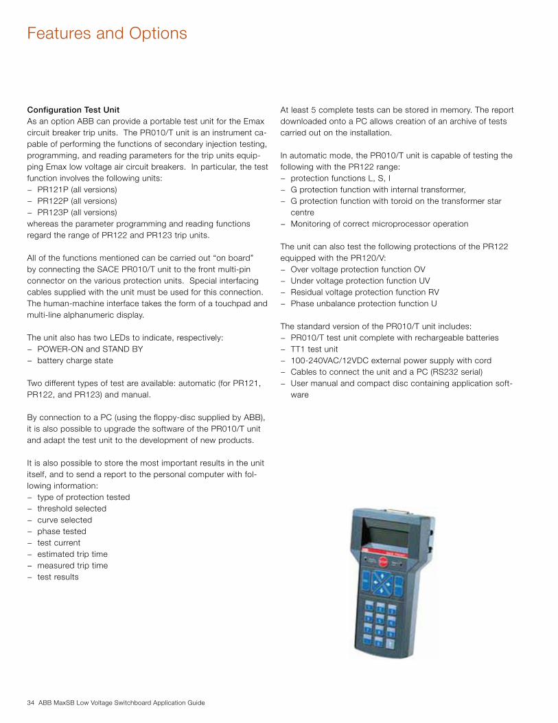
The standard version of the PR010/T unit includes: − PR010/T test unit complete with rechargeable batteries − TT1 test unit − 100-240VAC/12VDC external power supply with cord − Cables to connect the unit and a PC (RS232 serial) − User manual and compact disc containing application soft-
ware
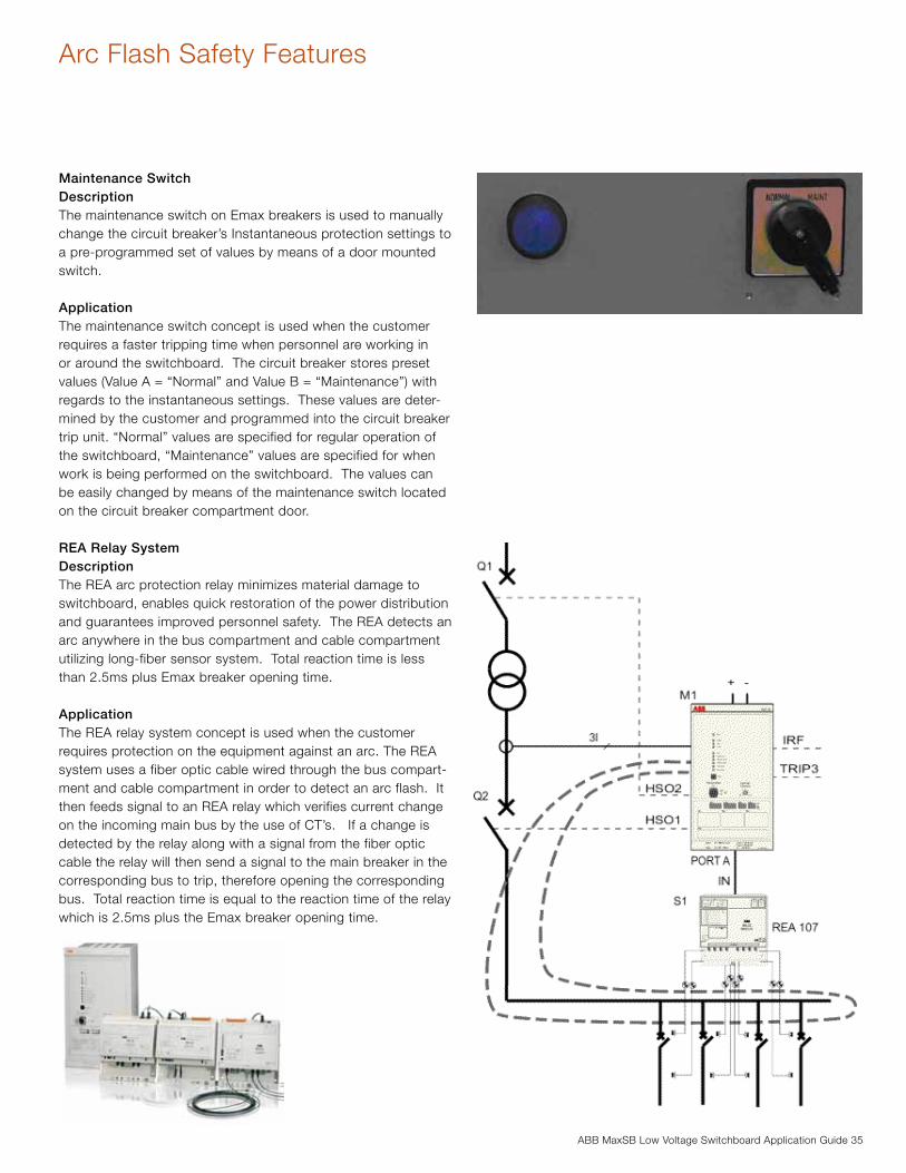
ABB MaxSB Low Voltage Switchboard Application Guide 35
Arc Flash Safety Features
Maintenance SwitchDescriptionThe maintenance switch on Emax breakers is used to manually change the circuit breaker’s Instantaneous protection settings to a pre-programmed set of values by means of a door mounted switch.
ApplicationThe maintenance switch concept is used when the customer requires a faster tripping time when personnel are working in or around the switchboard. The circuit breaker stores preset values (Value A = “Normal” and Value B = “Maintenance”) with regards to the instantaneous settings. These values are deter-mined by the customer and programmed into the circuit breaker trip unit. “Normal” values are specified for regular operation of the switchboard, “Maintenance” values are specified for when work is being performed on the switchboard. The values can be easily changed by means of the maintenance switch located on the circuit breaker compartment door.
REA Relay SystemDescriptionThe REA arc protection relay minimizes material damage to switchboard, enables quick restoration of the power distribution and guarantees improved personnel safety. The REA detects an arc anywhere in the bus compartment and cable compartment utilizing long-fiber sensor system. Total reaction time is less than 2.5ms plus Emax breaker opening time.
ApplicationThe REA relay system concept is used when the customer requires protection on the equipment against an arc. The REA system uses a fiber optic cable wired through the bus compart-ment and cable compartment in order to detect an arc flash. It then feeds signal to an REA relay which verifies current change on the incoming main bus by the use of CT’s. If a change is detected by the relay along with a signal from the fiber optic cable the relay will then send a signal to the main breaker in the corresponding bus to trip, therefore opening the corresponding bus. Total reaction time is equal to the reaction time of the relay which is 2.5ms plus the Emax breaker opening time.
36 ABB MaxSB Low Voltage Switchboard Application Guide
Conduit Layouts
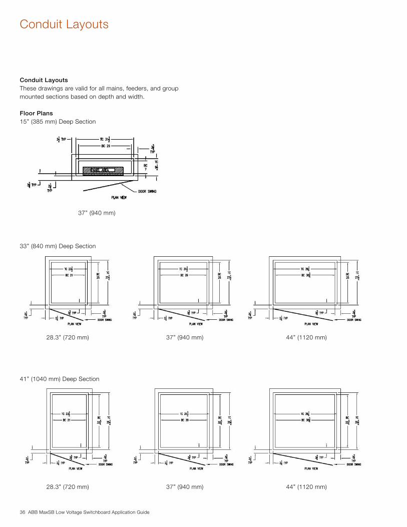
Conduit LayoutsThese drawings are valid for all mains, feeders, and group mounted sections based on depth and width.
Floor Plans15” (385 mm) Deep Section
33” (840 mm) Deep Section
41” (1040 mm) Deep Section
28.3” (720 mm) 37” (940 mm) 44” (1120 mm)
28.3” (720 mm) 37” (940 mm) 44” (1120 mm)
37” (940 mm)

ABB MaxSB Low Voltage Switchboard Application Guide 37
Notes
28.3” (720 mm) 37” (940 mm) 44” (1120 mm)
28.3” (720 mm) 37” (940 mm) 44” (1120 mm)

38 ABB MaxSB Low Voltage Switchboard Application Guide
Notes

ABB MaxSB Low Voltage Switchboard Application Guide 39
Notes

Contact us
2TD
C29
0000
C02
R01
12
/201
0 S
ubje
ct t
o ch
ange
with
out
notic
e
ABB, Inc.Low Voltage Products & Systems3700 West Sam Houston Parkway SouthSuite 507FHouston, TX 77042Phone: 713-587-8055E-mail: [email protected]
www.abb.us/lowvoltage