Application example 08/2016 Plant Data Interface for the ... · more secure. Siemens strongly...
47
https://support.industry.siemens.com/cs/ww/en/view/86302104 Application example 08/2016 Plant Data Interface for the Food & Beverage Industry PDI Interface test tool
Transcript of Application example 08/2016 Plant Data Interface for the ... · more secure. Siemens strongly...

https://support.industry.siemens.com/cs/ww/en/view/86302104
Application example 08/2016
Plant Data Interface for the Food & Beverage Industry PDI Interface test tool
Warranty and liability
PDI Interface Test Tool Entry-ID: 86302104, V1.0, 08/2016 2
S
iem
en
s A
G 2
01
6 A
ll ri
gh
ts r
ese
rve
d
Warranty and liability
Note The Application Examples are not binding and do not claim to be complete regarding the circuits shown, equipping and any eventuality. The Application Examples do not represent customer-specific solutions. They are only intended to provide support for typical applications. You are responsible for ensuring that the described products are used correctly. These Application Examples do not relieve you of the responsibility to use safe practices in application, installation, operation and maintenance. When using these Application Examples, you recognize that we cannot be made liable for any damage/claims beyond the liability clause described. We reserve the right to make changes to these Application Examples at any time without prior notice. If there are any deviations between the recommendations provided in these Application Examples and other Siemens publications – e.g. Catalogs – the contents of the other documents have priority.
We do not accept any liability for the information contained in this document. Any claims against us – based on whatever legal reason – resulting from the use of the examples, information, programs, engineering and performance data etc., described in this Application Example shall be excluded. Such an exclusion shall not apply in the case of mandatory liability, e.g. under the German Product Liability Act (“Produkthaftungsgesetz”), in case of intent, gross negligence, or injury of life, body or health, guarantee for the quality of a product, fraudulent concealment of a deficiency or breach of a condition which goes to the root of the contract (“wesentliche Vertragspflichten”). The damages for a breach of a substantial contractual obligation are, however, limited to the foreseeable damage, typical for the type of contract, except in the event of intent or gross negligence or injury to life, body or health. The above provisions do not imply a change of the burden of proof to your detriment. Any form of duplication or distribution of these Application Examples or excerpts hereof is prohibited without the expressed consent of the Siemens AG.
Security informa-tion
Siemens provides products and solutions with industrial security functions that support the secure operation of plants, systems, machines and networks. In order to protect plants, systems, machines and networks against cyber threats, it is necessary to implement – and continuously maintain – a holistic, state-of-the-art industrial security concept. Siemens’ products and solutions only form one element of such a concept. Customer is responsible to prevent unauthorized access to its plants, systems, machines and networks. Systems, machines and components should only be connected to the enterprise network or the internet if and to the extent necessary and with appropriate security measures (e.g. use of firewalls and network segmentation) in place. Additionally, Siemens’ guidance on appropriate security measures should be taken into account. For more information about industrial security, please visit http://www.siemens.com/industrialsecurity.
Siemens’ products and solutions undergo continuous development to make them more secure. Siemens strongly recommends to apply product updates as soon as available and to always use the latest product versions. Use of product versions that are no longer supported, and failure to apply latest updates may increase customer’s exposure to cyber threats. To stay informed about product updates, subscribe to the Siemens Industrial Security RSS Feed under http://www.siemens.com/industrialsecurity.
Table of contents
PDI Interface Test Tool Entry-ID: 86302104, V1.0, 08/2016 3
S
iem
en
s A
G 2
01
6 A
ll ri
gh
ts r
ese
rve
d
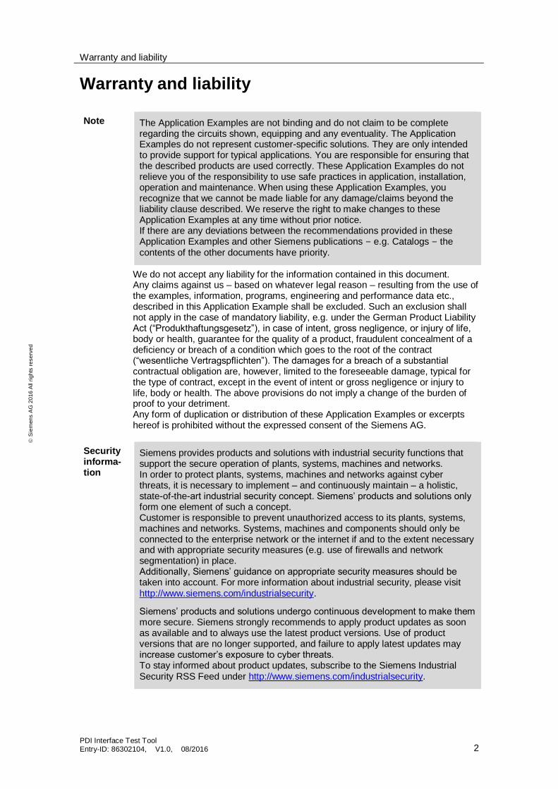
Table of contents Warranty and liability ............................................................................................... 2
1 PDI Interface test tool ..................................................................................... 4
1.1 Overview ........................................................................................... 4 1.2 Description of the core functionality .................................................... 6 1.3 Overview of the test environment ....................................................... 8 1.4 Hardware and software components .................................................. 9 1.5 System requirements ....................................................................... 10
2 Commissioning ............................................................................................ 11
2.1 Installation ....................................................................................... 11 2.1.1 PDF printer on engineering system .................................................. 12 2.1.2 PDF printer at Comfort Panel ........................................................... 12 2.2 Project configuration and runtime start ............................................. 13 2.2.1 Configuring the runtime simulation ................................................... 13 2.2.2 Use of a Comfort Panel.................................................................... 14 2.2.3 OPC UA configuration ..................................................................... 19
3 Controlling the application .......................................................................... 24
3.1 Configuration ................................................................................... 25 3.1.1 Configure connection ....................................................................... 25 3.1.2 Entering test report information ........................................................ 26 3.1.3 Configuring the interface .................................................................. 27 3.1.4 Modes & States configuration .......................................................... 29 3.2 Establishing a connection ................................................................ 30 3.3 Interface test.................................................................................... 31 3.3.1 General settings and test control ...................................................... 31 3.3.2 Machine control using LCU .............................................................. 33 3.3.3 PackTag review methods ................................................................. 34 3.3.4 PackTag test status ......................................................................... 35 3.3.5 PackTag recording archives ............................................................. 37 3.3.6 Logs ................................................................................................ 38 3.3.7 Report view ..................................................................................... 39 3.4 Messages ........................................................................................ 40 3.5 Service ............................................................................................ 41
4 OPC UA Variables......................................................................................... 42
5 Related literature .......................................................................................... 47
6 History .......................................................................................................... 47
1 PDI Interface test tool
PDI Interface Test Tool Entry-ID: 86302104, V1.0, 08/2016 4
S
iem
en
s A
G 2
01
6 A
ll ri
gh
ts r
ese
rve
d
1 PDI Interface test tool
1.1 Overview
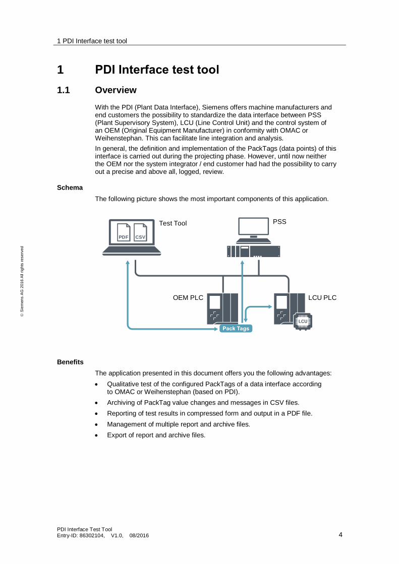
With the PDI (Plant Data Interface), Siemens offers machine manufacturers and end customers the possibility to standardize the data interface between PSS (Plant Supervisory System), LCU (Line Control Unit) and the control system of an OEM (Original Equipment Manufacturer) in conformity with OMAC or Weihenstephan. This can facilitate line integration and analysis.
In general, the definition and implementation of the PackTags (data points) of this interface is carried out during the projecting phase. However, until now neither the OEM nor the system integrator / end customer had had the possibility to carry out a precise and above all, logged, review.
Schema
The following picture shows the most important components of this application.
PSS
LCU PLCOEM PLC
PDF CSV
Test Tool
Benefits
The application presented in this document offers you the following advantages:
Qualitative test of the configured PackTags of a data interface according to OMAC or Weihenstephan (based on PDI).
Archiving of PackTag value changes and messages in CSV files.
Reporting of test results in compressed form and output in a PDF file.
Management of multiple report and archive files.
Export of report and archive files.
1 PDI Interface test tool
PDI Interface Test Tool Entry-ID: 86302104, V1.0, 08/2016 5
S
iem
en
s A
G 2
01
6 A
ll ri
gh
ts r
ese
rve
d
Delimitation
This application does not contain a description of:
Installation and operation of the TIA Portal
Installation and operation of HW-Config (STEP 7 Classic)
Installation and operation of SIMOTION SCOUT
Installation and configuration of a PDF printer driver
Required knowledge
A basic working knowledge of the required Siemens applications (see delimitation) as well as a working knowledge of Personal Computers, Microsoft operating systems and TCP/IP networks is needed.
Technical requirements
All participant units must be networked in an Ethernet network. Communication between the application and the OEM PLC must take place via TCP/IP or OPC UA.
Scope
This application is effective for:
TIA Portal V13 SP1 Update 9 or higher
SIMATIC S7-300/400/1200/1500
SIMOTION V4.4 Hotfix 11
Control systems with an OPC UA server
PC single-station system for WinCC Runtime
Note Alternatively to the PC single-station system, a Comfort Panel of one of the following series: 1200, 1500 or 2200 (Firmware V13.0.1.0) with one SD card (e.g. 6AV2 181-8XP00-0AX0) can be used. However, there will be a brief performance problem, in particular after generating the report.
1 PDI Interface test tool
PDI Interface Test Tool Entry-ID: 86302104, V1.0, 08/2016 6
S
iem
en
s A
G 2
01
6 A
ll ri
gh
ts r
ese
rve
d
1.2 Description of the core functionality
With the help of this application it is possible to determine the quality of a data interface based on the Siemens Plant Data Interface (PDI). For this purpose all the PackTags used are checked according to their type and according to diverse criteria in an active test. The current test status of the PackTags can be checked all the time, to see which tags are still open for test. After the interface test is finished the result can be send to a printer. In addition, all the messages and value changes of the PackTags are archived in CSV files and remain available for a later detailed diagnosis.
For printing the protocol a software or hardware printer can be used. The recommendation is to use a PDF printer to make sure all features of the application can be used.
The application is available as a TIA WinCC Comfort Project and can be simulated on an Engineering Station or transferred to an existing Comfort Panel and used.
Note At the present time and due to the system characteristics, it is not possible to determine automatically the data structure of a projected interface. Therefore, the User must configure the data interface before a test. This is done mainly via the configuration pages of the application. However, if the communication takes place via OPC UA, the variables connection in the TIA Project must also be adjusted.
1 PDI Interface test tool
PDI Interface Test Tool Entry-ID: 86302104, V1.0, 08/2016 7
S
iem
en
s A
G 2
01
6 A
ll ri
gh
ts r
ese
rve
d
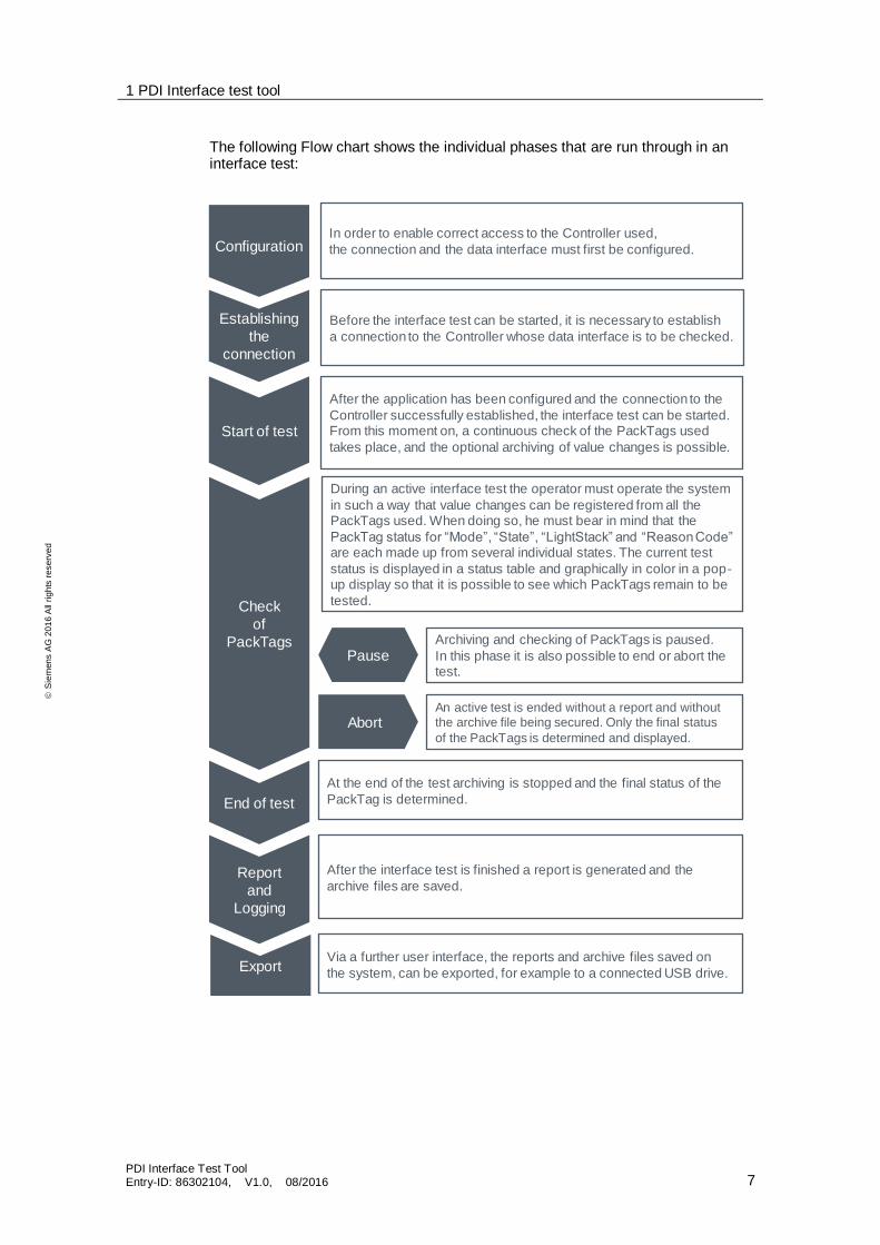
The following Flow chart shows the individual phases that are run through in an interface test:
Check
of
PackTags
During an active interface test the operator must operate the system
in such a way that value changes can be registered from all the PackTags used. When doing so, he must bear in mind that the
PackTag status for “Mode”, “State”, “LightStack” and “Reason Code” are each made up from several individual states. The current test
status is displayed in a status table and graphically in color in a pop-up display so that it is possible to see which PackTags remain to be
tested.
Pause
Abort
Archiving and checking of PackTags is paused.
In this phase it is also possible to end or abort the test.
An active test is ended without a report and without the archive file being secured. Only the final status
of the PackTags is determined and displayed.
End of test
At the end of the test archiving is stopped and the final status of the
PackTag is determined.
Report
and
Logging
After the interface test is finished a report is generated and the
archive files are saved.
ExportVia a further user interface, the reports and archive files saved on
the system, can be exported, for example to a connected USB drive.
Start of test
ConfigurationIn order to enable correct access to the Controller used,
the connection and the data interface must first be configured.
Establishing
the
connection
Before the interface test can be started, it is necessary to establish
a connection to the Controller whose data interface is to be checked.
After the application has been configured and the connection to the
Controller successfully established, the interface test can be started. From this moment on, a continuous check of the PackTags used
takes place, and the optional archiving of value changes is possible.
1 PDI Interface test tool
PDI Interface Test Tool Entry-ID: 86302104, V1.0, 08/2016 8
S
iem
en
s A
G 2
01
6 A
ll ri
gh
ts r
ese
rve
d
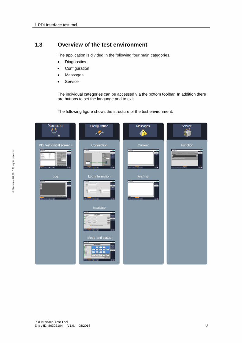
1.3 Overview of the test environment
The application is divided in the following four main categories.
Diagnostics
Configuration
Messages
Service
The individual categories can be accessed via the bottom toolbar. In addition there are buttons to set the language and to exit.
The following figure shows the structure of the test environment:
PDI test (initial screen) Connection Current Function
Log Log information Archive
Interface
Mode and status
1 PDI Interface test tool
PDI Interface Test Tool Entry-ID: 86302104, V1.0, 08/2016 9
S
iem
en
s A
G 2
01
6 A
ll ri
gh
ts r
ese
rve
d
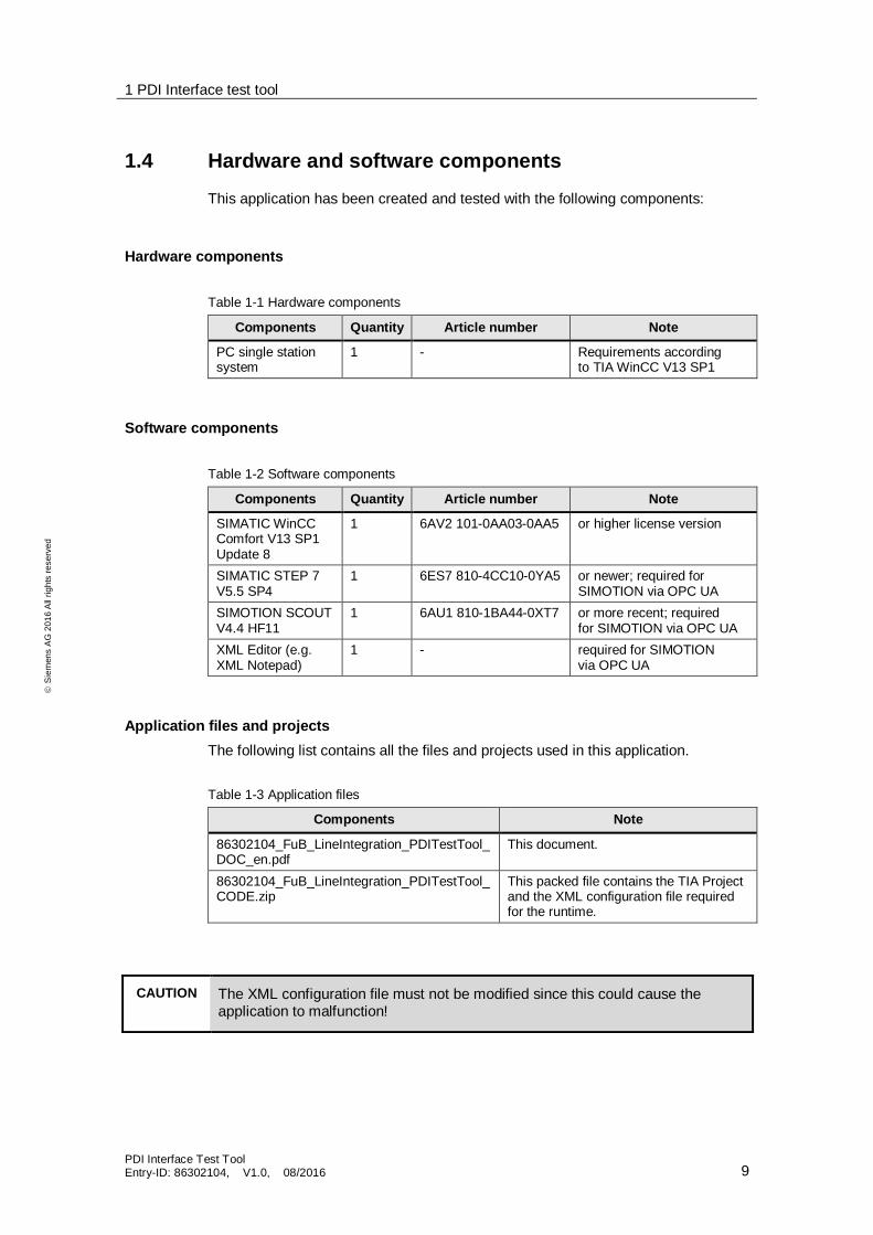
1.4 Hardware and software components
This application has been created and tested with the following components:
Hardware components
Table 1-1 Hardware components
Components Quantity Article number Note
PC single station system
1 - Requirements according to TIA WinCC V13 SP1
Software components
Table 1-2 Software components
Components Quantity Article number Note SIMATIC WinCC Comfort V13 SP1 Update 8
1 6AV2 101-0AA03-0AA5 or higher license version
SIMATIC STEP 7 V5.5 SP4
1 6ES7 810-4CC10-0YA5 or newer; required for SIMOTION via OPC UA
SIMOTION SCOUT V4.4 HF11
1 6AU1 810-1BA44-0XT7 or more recent; required for SIMOTION via OPC UA
XML Editor (e.g. XML Notepad)
1 - required for SIMOTION via OPC UA
Application files and projects
The following list contains all the files and projects used in this application.
Table 1-3 Application files
Components Note 86302104_FuB_LineIntegration_PDITestTool_DOC_en.pdf
This document.
86302104_FuB_LineIntegration_PDITestTool_CODE.zip
This packed file contains the TIA Project and the XML configuration file required for the runtime.
CAUTION The XML configuration file must not be modified since this could cause the application to malfunction!
1 PDI Interface test tool
PDI Interface Test Tool Entry-ID: 86302104, V1.0, 08/2016 10
S
iem
en
s A
G 2
01
6 A
ll ri
gh
ts r
ese
rve
d
1.5 System requirements
The following general and system-dependent (WinCC Runtime or Comfort Panel) requirements must be observed when using the application:
free access to port for incorporation into TCP/IP network
freely available IP address within TCP/IP network
when using a WinCC Runtime
– recommended PC System requirements for SIMATIC WinCC Comfort V13 SP1 (Core i5 3.3GHz or similar, 8 GB RAM)
– write permission for Partition C
– at least 2GB available RAM
when using a Comfort Panel
– 2GB SD card in the data slot
sufficient free memory space on Partition C / SD card
– approx. 110MB for Message archive
– approx. 360MB per test report for PDF and CSV files
PDF printer driver installed and configured
CAUTION Due to the characteristics of the system, the current version of the application cannot record rapid value changes of the PackTags smaller than 100 ms. In particular when checking the status changes this can cause an unwarranted warning to be registered in the log.
2 Commissioning
PDI Interface Test Tool Entry-ID: 86302104, V1.0, 08/2016 11
S
iem
en
s A
G 2
01
6 A
ll ri
gh
ts r
ese
rve
d
2 Commissioning
2.1 Installation
In order to use this application, an Engineering Station with WinCC Comfort/Advanced/Professional V13 SP1 Update 8 (or higher) is needed. Additionally, STEP 7 Classic, SIMOTION SCOUT and an XML Editor (e.g. XML Notepad) will be required if machine control is via SIMOTION.
Perform the following tasks on the test system:
1. Install and configure a PDF printer driver as standard printer for the test system used:
– Chapter 2.1.1 PDF printer on engineering system
– Chapter 2.1.2 PDF printer at Comfort Panel
Note In principle, either a hardware or a software printer can be used as standard printer. However, output as a PDF is recommended, as this allows the application to be used to full advantage.
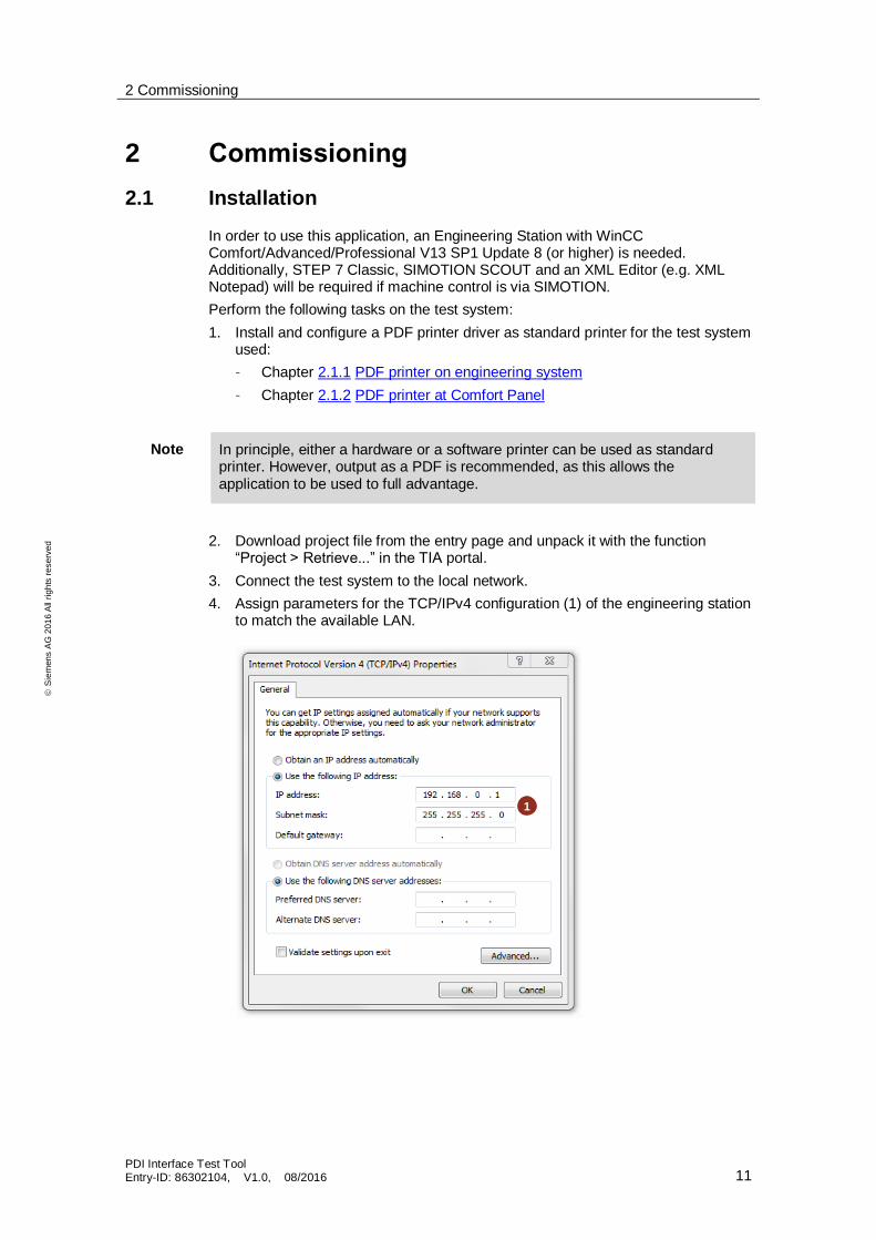
2. Download project file from the entry page and unpack it with the function “Project > Retrieve...” in the TIA portal.
3. Connect the test system to the local network.
4. Assign parameters for the TCP/IPv4 configuration (1) of the engineering station to match the available LAN.
1
2 Commissioning
PDI Interface Test Tool Entry-ID: 86302104, V1.0, 08/2016 12
S
iem
en
s A
G 2
01
6 A
ll ri
gh
ts r
ese
rve
d
2.1.1 PDF printer on engineering system
The WinCC Runtime runs on a PC system. There are numerous freeware programs available with which PDF documents can be created (e.g. PDF Creator). The configuration takes place in the devices and printer management, independently of the Windows operating system used. Here, too, the PDF printer already can be selected as standard printer. In a later step it’s also possible to change the standard printer.
Make the following settings:
Storage location: “C:\Storage Card SD\PDI_Reports\“
File name: “PDI_Report_YYYY_MM_DD_HH_MM_SS.pdf“
Activate automatic saving
Please refer to the documentation of the PDF program used to see where these settings can be configured.
2.1.2 PDF printer at Comfort Panel
On a Comfort Panel the report just can be printed by the selected standard printer.
In the entry "Printing with SIMATIC Comfort Panels" you will find further information on this topic. The documents that can be downloaded from there describe all the necessary installation steps for the PDF printer driver.
Make the following settings:
Control panel > Printer
– Activate color options
Desktop > PDFsettings
– Main storage path: “SD”
– Filing location: “\Storage Card SD\PDI_Reports\”
– Activate monitor and report printing
– File name: “PDI_Report_YYYY_MM_DD_HH_MM_SS.pdf”
CAUTION When using a Comfort Panel the configuration of the standard printer cannot be changed while the application is running!
2 Commissioning
PDI Interface Test Tool Entry-ID: 86302104, V1.0, 08/2016 13
S
iem
en
s A
G 2
01
6 A
ll ri
gh
ts r
ese
rve
d
2.2 Project configuration and runtime start
This chapter describes the steps for the configuration of the test application depending on the selected Runtime system and the runtime start.
2.2.1 Configuring the runtime simulation
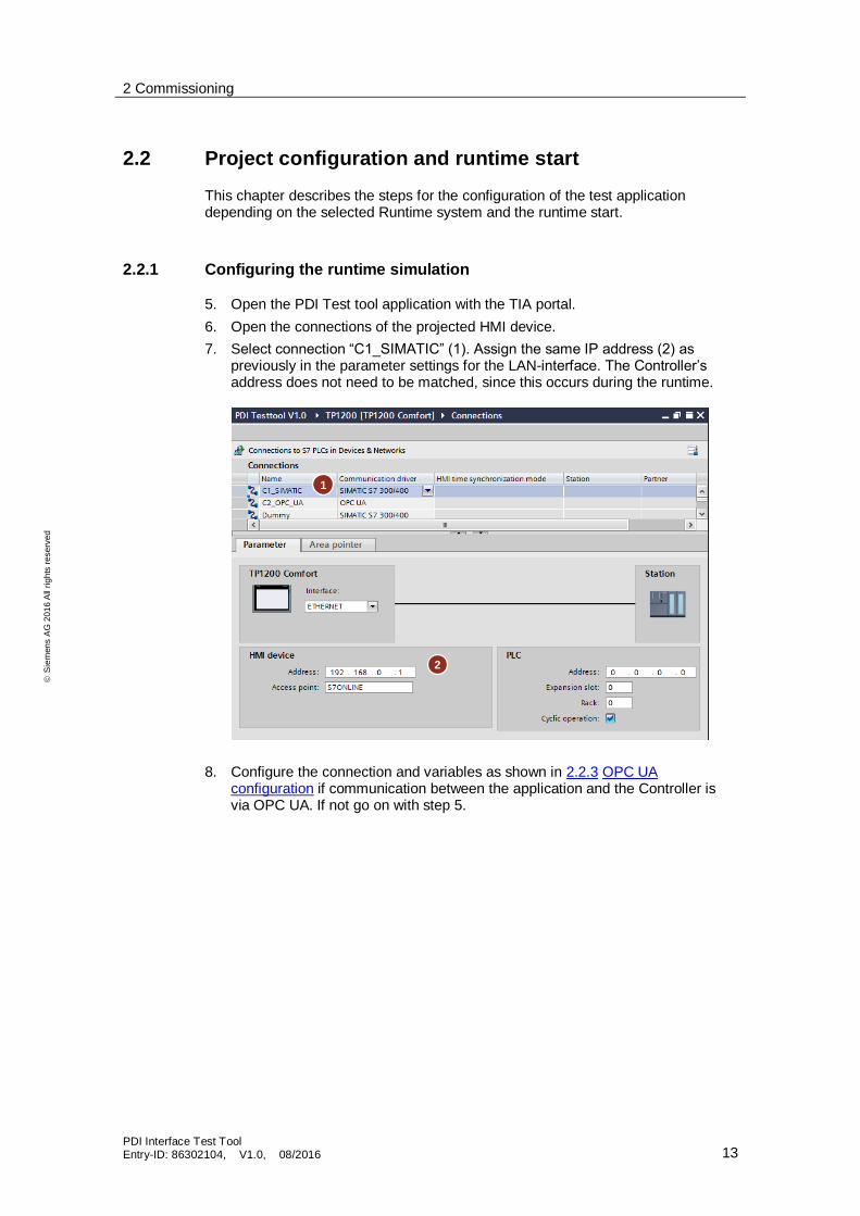
5. Open the PDI Test tool application with the TIA portal.
6. Open the connections of the projected HMI device.
7. Select connection “C1_SIMATIC” (1). Assign the same IP address (2) as previously in the parameter settings for the LAN-interface. The Controller’s address does not need to be matched, since this occurs during the runtime.
8. Configure the connection and variables as shown in 2.2.3 OPC UA configuration if communication between the application and the Controller is via OPC UA. If not go on with step 5.
1
2
2 Commissioning
PDI Interface Test Tool Entry-ID: 86302104, V1.0, 08/2016 14
S
iem
en
s A
G 2
01
6 A
ll ri
gh
ts r
ese
rve
d
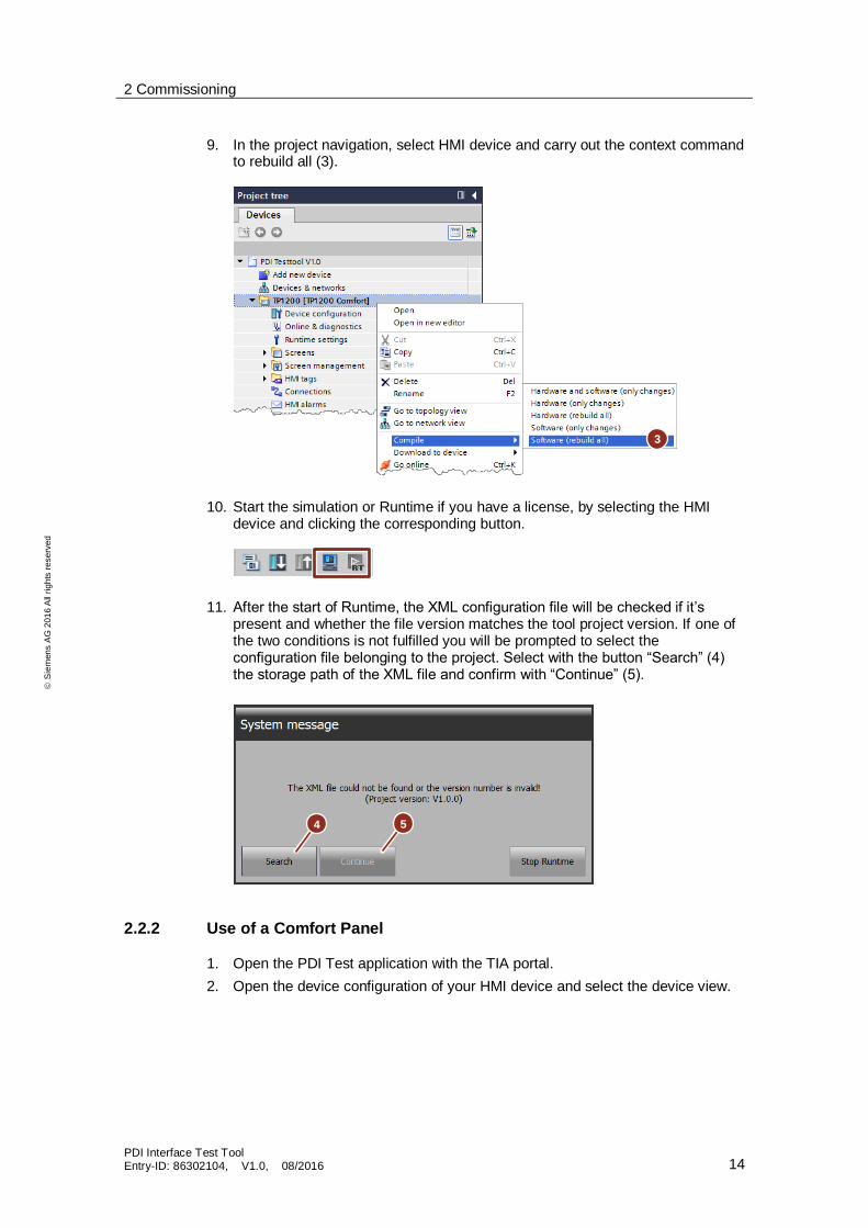
9. In the project navigation, select HMI device and carry out the context command to rebuild all (3).
10. Start the simulation or Runtime if you have a license, by selecting the HMI device and clicking the corresponding button.
11. After the start of Runtime, the XML configuration file will be checked if it’s present and whether the file version matches the tool project version. If one of the two conditions is not fulfilled you will be prompted to select the configuration file belonging to the project. Select with the button “Search” (4) the storage path of the XML file and confirm with “Continue” (5).
2.2.2 Use of a Comfort Panel
1. Open the PDI Test application with the TIA portal.
2. Open the device configuration of your HMI device and select the device view.
3
4 5
2 Commissioning
PDI Interface Test Tool Entry-ID: 86302104, V1.0, 08/2016 15
S
iem
en
s A
G 2
01
6 A
ll ri
gh
ts r
ese
rve
d
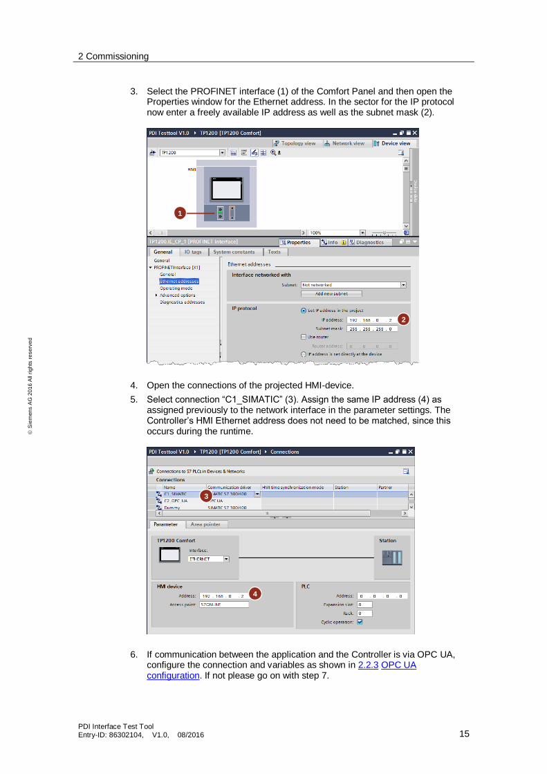
3. Select the PROFINET interface (1) of the Comfort Panel and then open the Properties window for the Ethernet address. In the sector for the IP protocol now enter a freely available IP address as well as the subnet mask (2).
4. Open the connections of the projected HMI-device.
5. Select connection “C1_SIMATIC” (3). Assign the same IP address (4) as assigned previously to the network interface in the parameter settings. The Controller’s HMI Ethernet address does not need to be matched, since this occurs during the runtime.
6. If communication between the application and the Controller is via OPC UA, configure the connection and variables as shown in 2.2.3 OPC UA configuration. If not please go on with step 7.
1
3
4
2
2 Commissioning
PDI Interface Test Tool Entry-ID: 86302104, V1.0, 08/2016 16
S
iem
en
s A
G 2
01
6 A
ll ri
gh
ts r
ese
rve
d
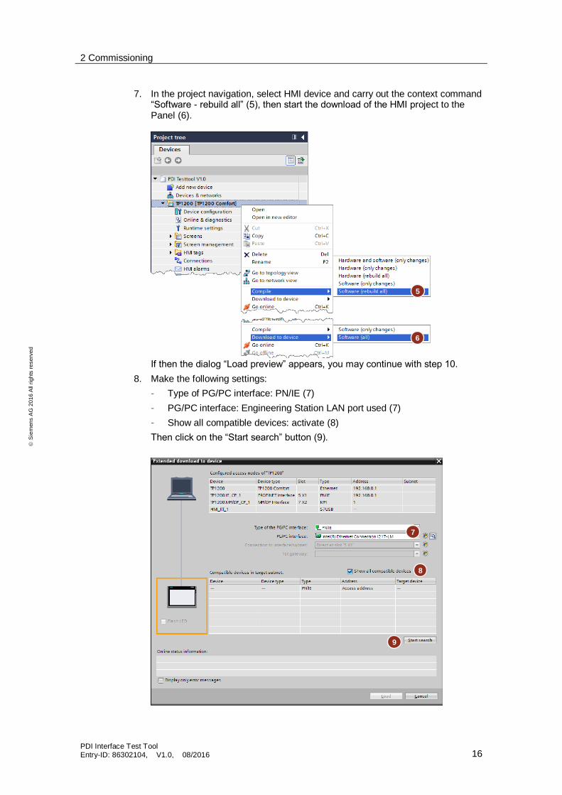
7. In the project navigation, select HMI device and carry out the context command “Software - rebuild all” (5), then start the download of the HMI project to the Panel (6).
If then the dialog “Load preview” appears, you may continue with step 10.
8. Make the following settings:
– Type of PG/PC interface: PN/IE (7)
– PG/PC interface: Engineering Station LAN port used (7)
– Show all compatible devices: activate (8)
Then click on the “Start search” button (9).
5
6
7
8
9
2 Commissioning
PDI Interface Test Tool Entry-ID: 86302104, V1.0, 08/2016 17
S
iem
en
s A
G 2
01
6 A
ll ri
gh
ts r
ese
rve
d
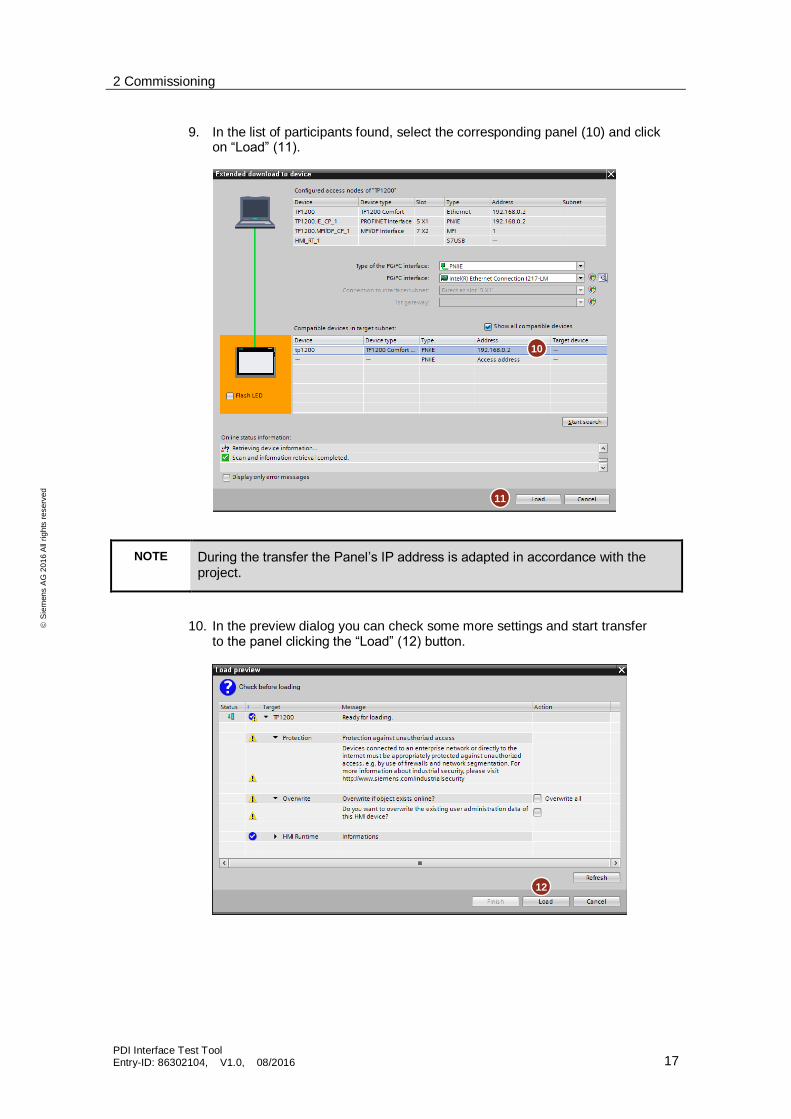
9. In the list of participants found, select the corresponding panel (10) and click on “Load” (11).
NOTE During the transfer the Panel’s IP address is adapted in accordance with the project.
10. In the preview dialog you can check some more settings and start transfer to the panel clicking the “Load” (12) button.
12
10
11
2 Commissioning
PDI Interface Test Tool Entry-ID: 86302104, V1.0, 08/2016 18
S
iem
en
s A
G 2
01
6 A
ll ri
gh
ts r
ese
rve
d
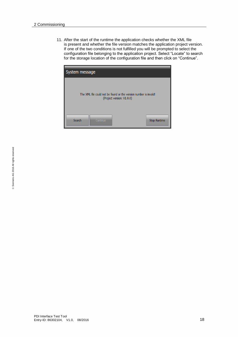
11. After the start of the runtime the application checks whether the XML file is present and whether the file version matches the application project version. If one of the two conditions is not fulfilled you will be prompted to select the configuration file belonging to the application project. Select “Locate” to search for the storage location of the configuration file and then click on “Continue”.
2 Commissioning
PDI Interface Test Tool Entry-ID: 86302104, V1.0, 08/2016 19
S
iem
en
s A
G 2
01
6 A
ll ri
gh
ts r
ese
rve
d
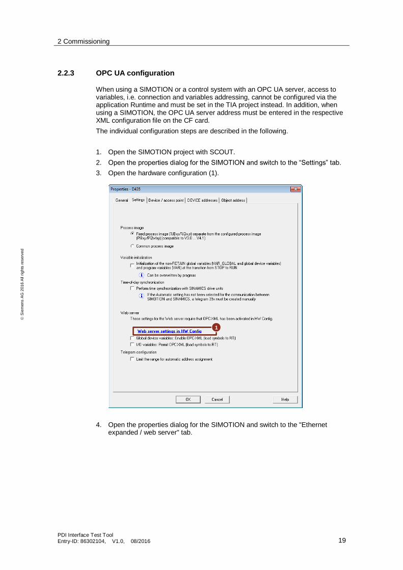
2.2.3 OPC UA configuration
When using a SIMOTION or a control system with an OPC UA server, access to variables, i.e. connection and variables addressing, cannot be configured via the application Runtime and must be set in the TIA project instead. In addition, when using a SIMOTION, the OPC UA server address must be entered in the respective XML configuration file on the CF card.
The individual configuration steps are described in the following.
1. Open the SIMOTION project with SCOUT.
2. Open the properties dialog for the SIMOTION and switch to the “Settings” tab.
3. Open the hardware configuration (1).
4. Open the properties dialog for the SIMOTION and switch to the "Ethernet expanded / web server" tab.
1
2 Commissioning
PDI Interface Test Tool Entry-ID: 86302104, V1.0, 08/2016 20
S
iem
en
s A
G 2
01
6 A
ll ri
gh
ts r
ese
rve
d
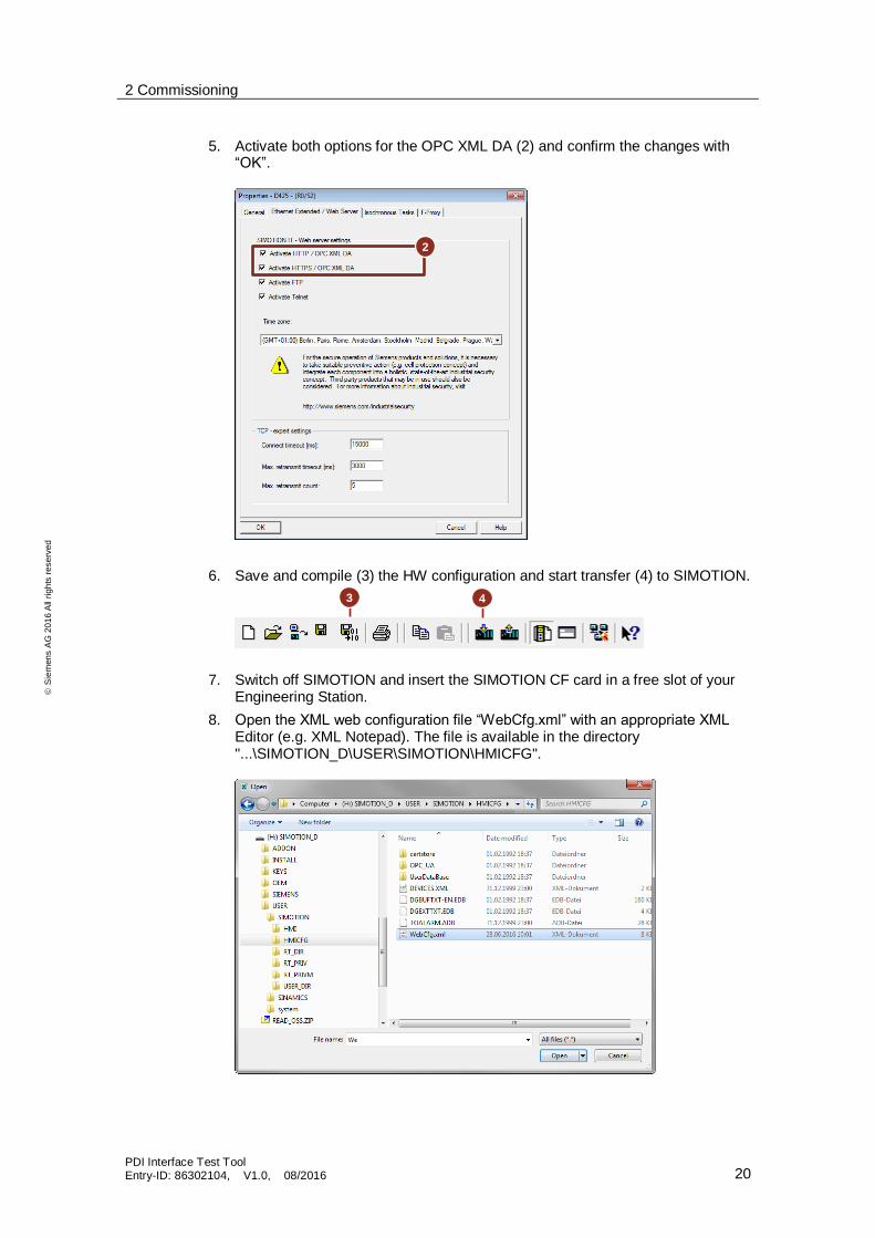
5. Activate both options for the OPC XML DA (2) and confirm the changes with “OK”.
6. Save and compile (3) the HW configuration and start transfer (4) to SIMOTION.
7. Switch off SIMOTION and insert the SIMOTION CF card in a free slot of your Engineering Station.
8. Open the XML web configuration file “WebCfg.xml” with an appropriate XML Editor (e.g. XML Notepad). The file is available in the directory "...\SIMOTION_D\USER\SIMOTION\HMICFG".
2
3 4
2 Commissioning
PDI Interface Test Tool Entry-ID: 86302104, V1.0, 08/2016 21
S
iem
en
s A
G 2
01
6 A
ll ri
gh
ts r
ese
rve
d
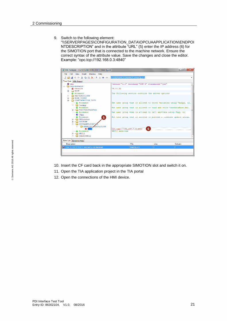
9. Switch to the following element: “\\SERVERPAGES\CONFIGURATION_DATA\OPCUAAPPLICATION\ENDPOINTDESCRIPTION” and in the attribute “URL” (5) enter the IP address (6) for the SIMOTION port that is connected to the machine network. Ensure the correct syntax of the attribute value. Save the changes and close the editor. Example: “opc.tcp://192.168.0.3:4840”
10. Insert the CF card back in the appropriate SIMOTION slot and switch it on.
11. Open the TIA application project in the TIA portal
12. Open the connections of the HMI device.
5
6
2 Commissioning
PDI Interface Test Tool Entry-ID: 86302104, V1.0, 08/2016 22
S
iem
en
s A
G 2
01
6 A
ll ri
gh
ts r
ese
rve
d
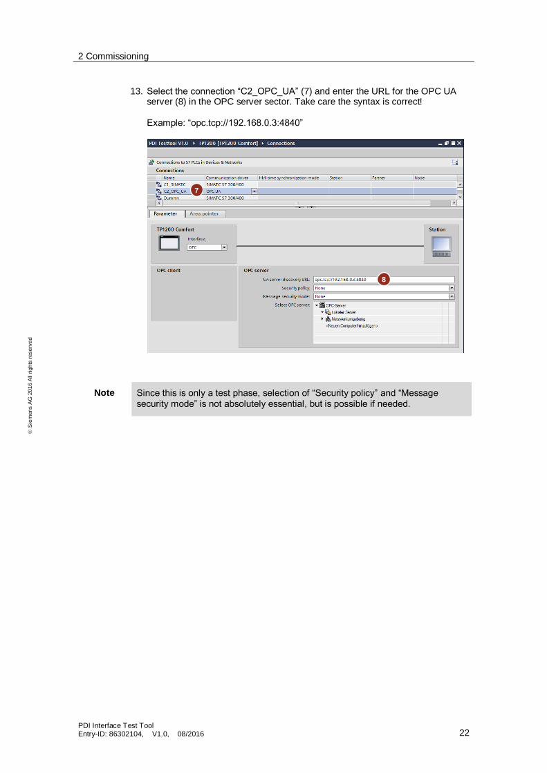
13. Select the connection “C2_OPC_UA” (7) and enter the URL for the OPC UA server (8) in the OPC server sector. Take care the syntax is correct! Example: “opc.tcp://192.168.0.3:4840”
Note Since this is only a test phase, selection of “Security policy” and “Message security mode” is not absolutely essential, but is possible if needed.
7
8

2 Commissioning
PDI Interface Test Tool Entry-ID: 86302104, V1.0, 08/2016 23
S
iem
en
s A
G 2
01
6 A
ll ri
gh
ts r
ese
rve
d
14. Open the variable table “External C2 – OPC UA”
15. Select one after another in sequence the PackTag (9) variables used in your data interface and enter the respective OPC variable under Address (10). Please take care about the correct selected data type (11) and the correct length of strings (12). Example: “PDI.BASIC.STATUS.CurMachSpeed”
Note In Chapter Error! Reference source not found. Error! Reference source not und. you will find a list of the available connection variables and the reference to
the PackTags, defined in the individual PDI versions.
16. In the project navigation, select HMI device and in the context menu carry out the command for complete transfer (13).
13
9
10 11
12
3 Controlling the application
PDI Interface Test Tool Entry-ID: 86302104, V1.0, 08/2016 24
S
iem
en
s A
G 2
01
6 A
ll ri
gh
ts r
ese
rve
d
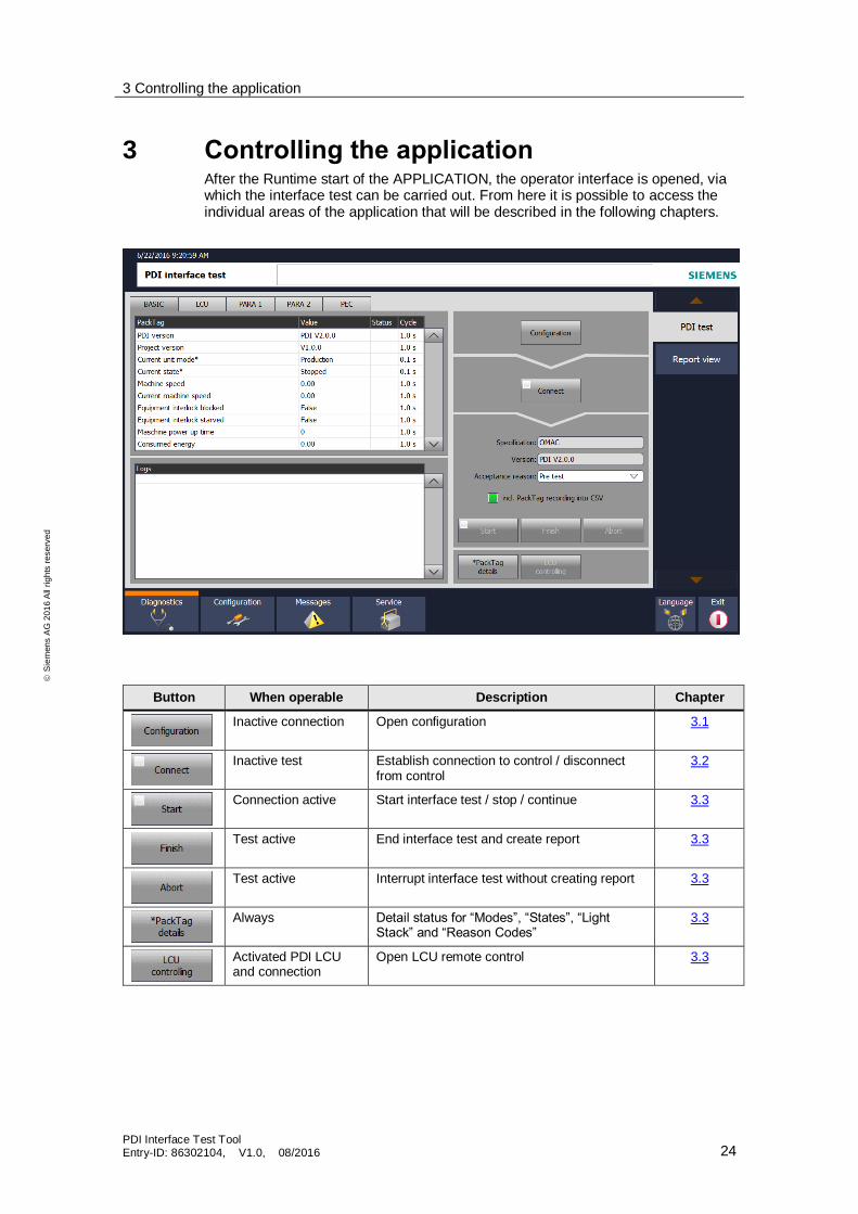
3 Controlling the application After the Runtime start of the APPLICATION, the operator interface is opened, via which the interface test can be carried out. From here it is possible to access the individual areas of the application that will be described in the following chapters.
Button When operable Description Chapter
Inactive connection Open configuration 3.1
Inactive test Establish connection to control / disconnect from control
3.2
Connection active Start interface test / stop / continue 3.3
Test active End interface test and create report 3.3
Test active Interrupt interface test without creating report 3.3
Always Detail status for “Modes”, “States”, “Light Stack” and “Reason Codes”
3.3
Activated PDI LCU and connection
Open LCU remote control 3.3
3 Controlling the application
PDI Interface Test Tool Entry-ID: 86302104, V1.0, 08/2016 25
S
iem
en
s A
G 2
01
6 A
ll ri
gh
ts r
ese
rve
d
3.1 Configuration
3.1.1 Configure connection
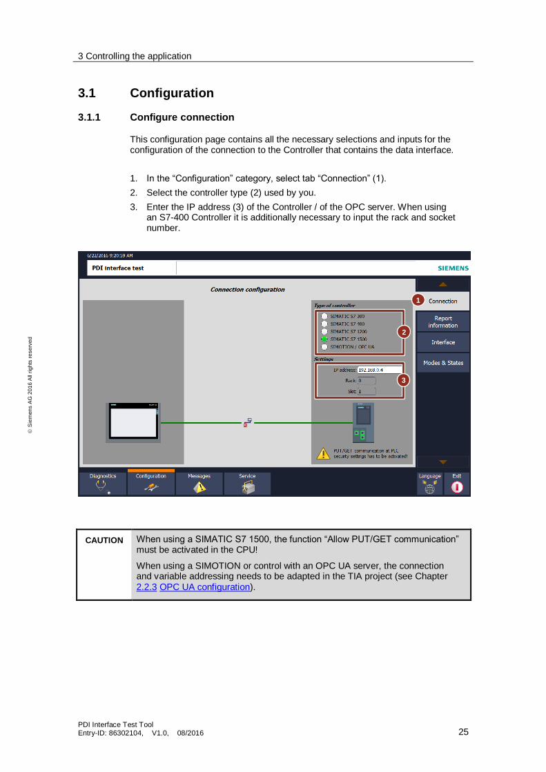
This configuration page contains all the necessary selections and inputs for the configuration of the connection to the Controller that contains the data interface.
1. In the “Configuration” category, select tab “Connection” (1).
2. Select the controller type (2) used by you.
3. Enter the IP address (3) of the Controller / of the OPC server. When using an S7-400 Controller it is additionally necessary to input the rack and socket number.
CAUTION When using a SIMATIC S7 1500, the function “Allow PUT/GET communication” must be activated in the CPU!
When using a SIMOTION or control with an OPC UA server, the connection and variable addressing needs to be adapted in the TIA project (see Chapter 2.2.3 OPC UA configuration).
1
2
3
3 Controlling the application
PDI Interface Test Tool Entry-ID: 86302104, V1.0, 08/2016 26
S
iem
en
s A
G 2
01
6 A
ll ri
gh
ts r
ese
rve
d
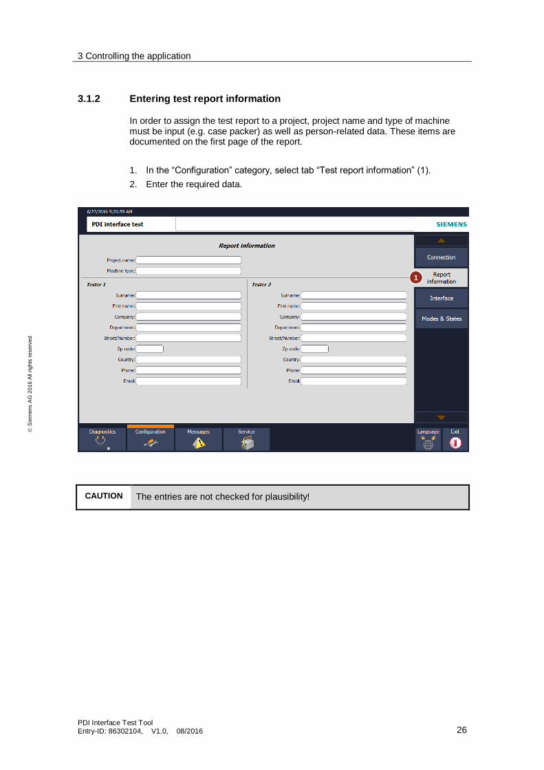
3.1.2 Entering test report information
In order to assign the test report to a project, project name and type of machine must be input (e.g. case packer) as well as person-related data. These items are documented on the first page of the report.
1. In the “Configuration” category, select tab “Test report information” (1).
2. Enter the required data.
CAUTION The entries are not checked for plausibility!
1
3 Controlling the application
PDI Interface Test Tool Entry-ID: 86302104, V1.0, 08/2016 27
S
iem
en
s A
G 2
01
6 A
ll ri
gh
ts r
ese
rve
d
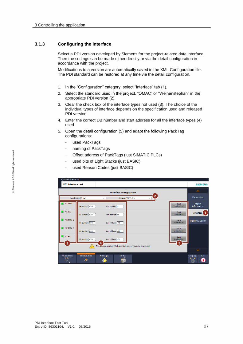
3.1.3 Configuring the interface
Select a PDI version developed by Siemens for the project-related data interface. Then the settings can be made either directly or via the detail configuration in accordance with the project.
Modifications to a version are automatically saved in the XML Configuration file. The PDI standard can be restored at any time via the detail configuration.
1. In the “Configuration” category, select “Interface” tab (1).
2. Select the standard used in the project, “OMAC” or “Weihenstephan” in the appropriate PDI version (2).
3. Clear the check box of the interface types not used (3). The choice of the individual types of interface depends on the specification used and released PDI version.
4. Enter the correct DB number and start address for all the interface types (4) used.
5. Open the detail configuration (5) and adapt the following PackTag configurations:
– used PackTags
– naming of PackTags
– Offset address of PackTags (just SIMATIC PLCs)
– used bits of Light Stacks (just BASIC)
– used Reason Codes (just BASIC)
1
3 4 5
2
3 Controlling the application
PDI Interface Test Tool Entry-ID: 86302104, V1.0, 08/2016 28
S
iem
en
s A
G 2
01
6 A
ll ri
gh
ts r
ese
rve
d
Note The PackTags of a deselected type will not be tested and will be marked as “not used” in the reporting. The system can show addressing errors on PackTags during the establishment of the connection. This can be ignored.
The reset to the original PDI PackTag configuration can be done via buttons in the detail configuration pop up.
CAUTION The selections and entries are not checked for plausibility!
When using a SIMATIC S7 1500 the attribute “Optimized module access” must be deactivated for the interface database!
When using a SIMOTION or a PLC with an OPC UA server, the connection and variable addressing needs to be adapted in the TIA project before the Runtime is started!
3 Controlling the application
PDI Interface Test Tool Entry-ID: 86302104, V1.0, 08/2016 29
S
iem
en
s A
G 2
01
6 A
ll ri
gh
ts r
ese
rve
d
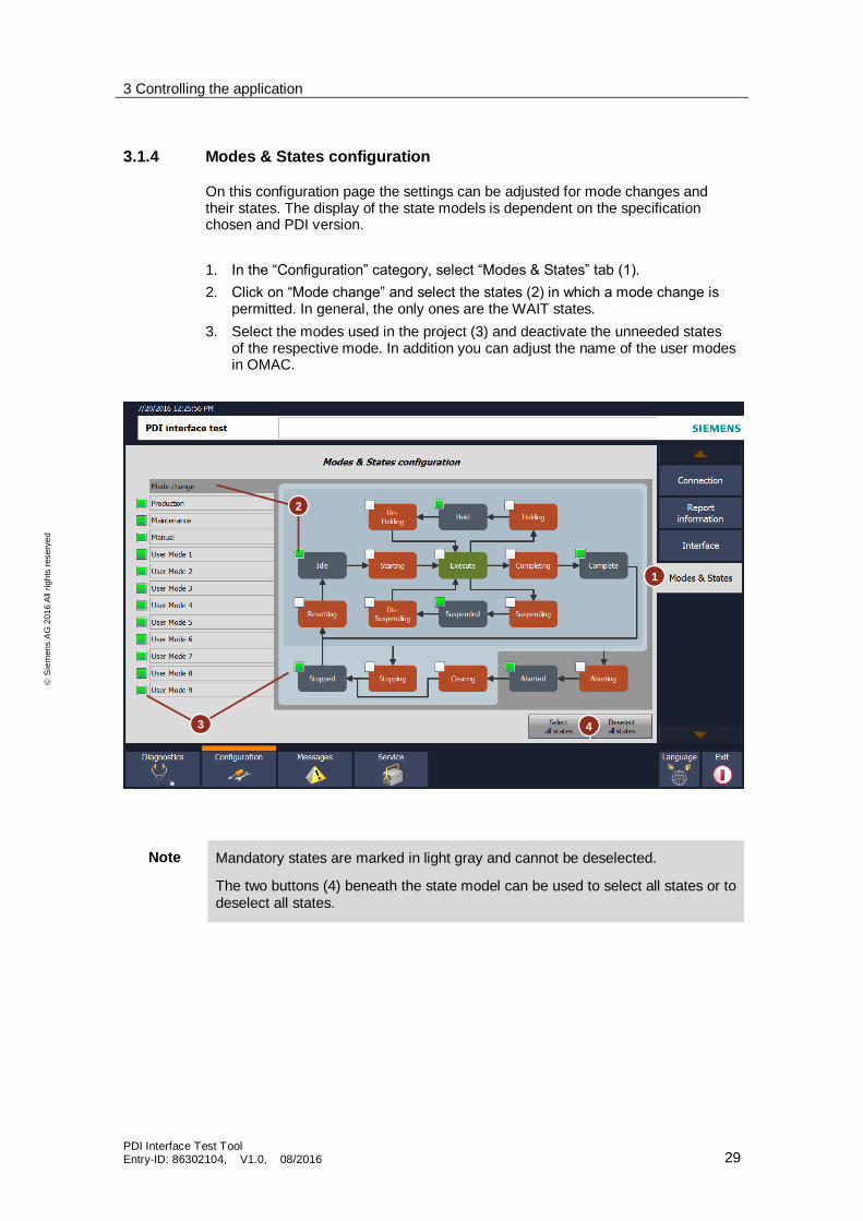
3.1.4 Modes & States configuration
On this configuration page the settings can be adjusted for mode changes and their states. The display of the state models is dependent on the specification chosen and PDI version.
1. In the “Configuration” category, select “Modes & States” tab (1).
2. Click on “Mode change” and select the states (2) in which a mode change is permitted. In general, the only ones are the WAIT states.
3. Select the modes used in the project (3) and deactivate the unneeded states of the respective mode. In addition you can adjust the name of the user modes in OMAC.
Note Mandatory states are marked in light gray and cannot be deselected.
The two buttons (4) beneath the state model can be used to select all states or to deselect all states.
1
2
3 4
3 Controlling the application
PDI Interface Test Tool Entry-ID: 86302104, V1.0, 08/2016 30
S
iem
en
s A
G 2
01
6 A
ll ri
gh
ts r
ese
rve
d
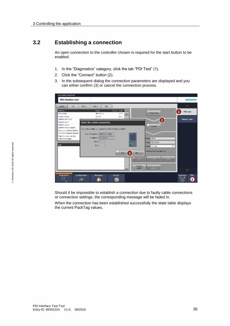
3.2 Establishing a connection
An open connection to the controller chosen is required for the start button to be enabled.
1. In the “Diagnostics” category, click the tab “PDI Test” (1).
2. Click the “Connect” button (2).
3. In the subsequent dialog the connection parameters are displayed and you can either confirm (3) or cancel the connection process.
Should it be impossible to establish a connection due to faulty cable connections or connection settings, the corresponding message will be faded in.
When the connection has been established successfully the state table displays the current PackTag values.
1
2
3
3 Controlling the application
PDI Interface Test Tool Entry-ID: 86302104, V1.0, 08/2016 31
S
iem
en
s A
G 2
01
6 A
ll ri
gh
ts r
ese
rve
d
3.3 Interface test
3.3.1 General settings and test control
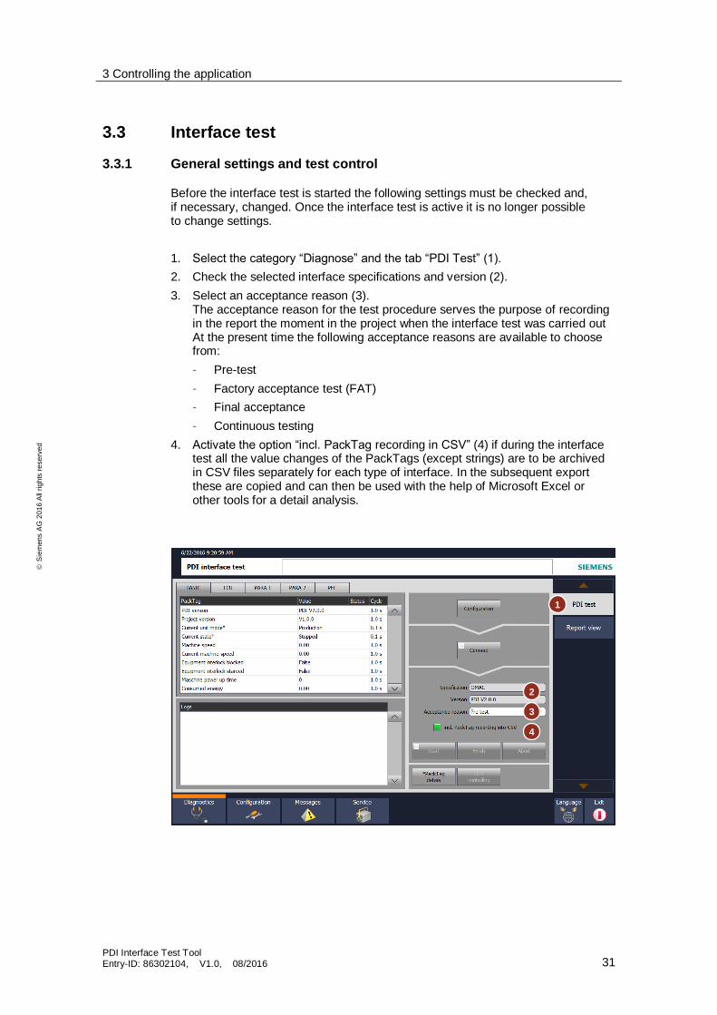
Before the interface test is started the following settings must be checked and, if necessary, changed. Once the interface test is active it is no longer possible to change settings.
1. Select the category “Diagnose” and the tab “PDI Test” (1).
2. Check the selected interface specifications and version (2).
3. Select an acceptance reason (3). The acceptance reason for the test procedure serves the purpose of recording in the report the moment in the project when the interface test was carried out At the present time the following acceptance reasons are available to choose from:
– Pre-test
– Factory acceptance test (FAT)
– Final acceptance
– Continuous testing
4. Activate the option “incl. PackTag recording in CSV” (4) if during the interface test all the value changes of the PackTags (except strings) are to be archived in CSV files separately for each type of interface. In the subsequent export these are copied and can then be used with the help of Microsoft Excel or other tools for a detail analysis.
1
2
3
4
3 Controlling the application
PDI Interface Test Tool Entry-ID: 86302104, V1.0, 08/2016 32
S
iem
en
s A
G 2
01
6 A
ll ri
gh
ts r
ese
rve
d
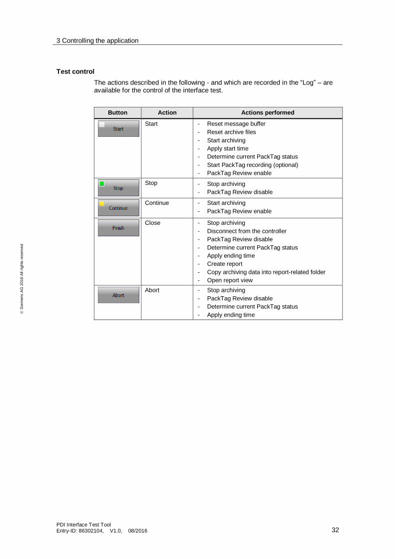
Test control
The actions described in the following - and which are recorded in the “Log” – are available for the control of the interface test.
Button Action Actions performed
Start - Reset message buffer
- Reset archive files
- Start archiving
- Apply start time
- Determine current PackTag status
- Start PackTag recording (optional)
- PackTag Review enable
Stop - Stop archiving
- PackTag Review disable
Continue - Start archiving
- PackTag Review enable
Close - Stop archiving
- Disconnect from the controller
- PackTag Review disable
- Determine current PackTag status
- Apply ending time
- Create report
- Copy archiving data into report-related folder
- Open report view
Abort - Stop archiving
- PackTag Review disable
- Determine current PackTag status
- Apply ending time
3 Controlling the application
PDI Interface Test Tool Entry-ID: 86302104, V1.0, 08/2016 33
S
iem
en
s A
G 2
01
6 A
ll ri
gh
ts r
ese
rve
d
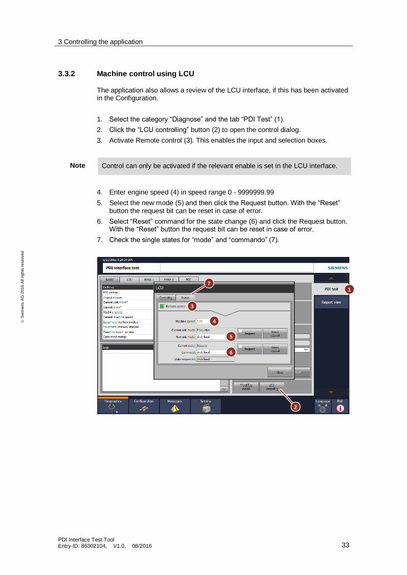
3.3.2 Machine control using LCU
The application also allows a review of the LCU interface, if this has been activated in the Configuration.
1. Select the category “Diagnose” and the tab “PDI Test” (1).
2. Click the “LCU controlling” button (2) to open the control dialog.
3. Activate Remote control (3). This enables the input and selection boxes.
Note Control can only be activated if the relevant enable is set in the LCU interface.
4. Enter engine speed (4) in speed range 0 - 9999999.99
5. Select the new mode (5) and then click the Request button. With the “Reset” button the request bit can be reset in case of error.
6. Select “Reset” command for the state change (6) and click the Request button. With the “Reset” button the request bit can be reset in case of error.
7. Check the single states for “mode” and “commando” (7).
1
2
6
3
4
5
7
3 Controlling the application
PDI Interface Test Tool Entry-ID: 86302104, V1.0, 08/2016 34
S
iem
en
s A
G 2
01
6 A
ll ri
gh
ts r
ese
rve
d
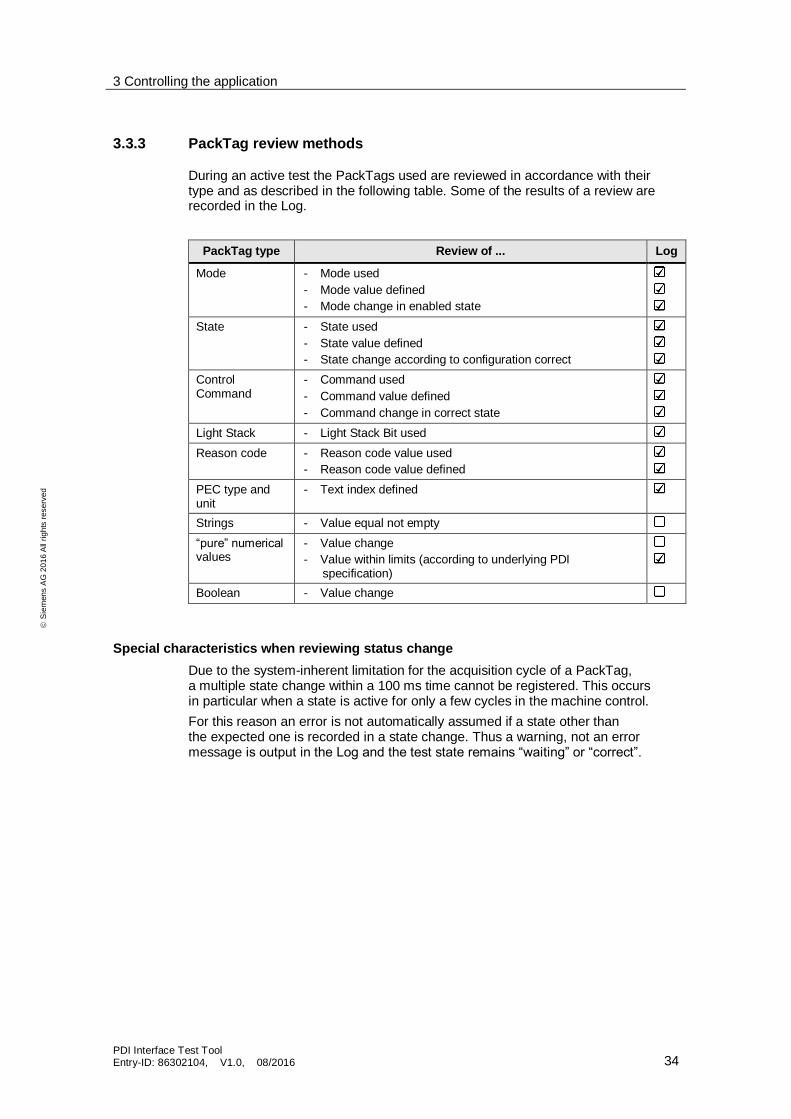
3.3.3 PackTag review methods
During an active test the PackTags used are reviewed in accordance with their type and as described in the following table. Some of the results of a review are recorded in the Log.
PackTag type Review of ... Log
Mode - Mode used
- Mode value defined
- Mode change in enabled state
State - State used
- State value defined
- State change according to configuration correct
Control Command
- Command used
- Command value defined
- Command change in correct state
Light Stack - Light Stack Bit used
Reason code - Reason code value used
- Reason code value defined
PEC type and unit
- Text index defined
Strings - Value equal not empty
“pure” numerical values
- Value change
- Value within limits (according to underlying PDI specification)
Boolean - Value change
Special characteristics when reviewing status change
Due to the system-inherent limitation for the acquisition cycle of a PackTag, a multiple state change within a 100 ms time cannot be registered. This occurs in particular when a state is active for only a few cycles in the machine control.
For this reason an error is not automatically assumed if a state other than the expected one is recorded in a state change. Thus a warning, not an error message is output in the Log and the test state remains “waiting” or “correct”.

3 Controlling the application
PDI Interface Test Tool Entry-ID: 86302104, V1.0, 08/2016 35
S
iem
en
s A
G 2
01
6 A
ll ri
gh
ts r
ese
rve
d
3.3.4 PackTag test status
To provide a general overview, for each type of interface there is a status table available for the display of the current test status of the individual PackTags. In it, name, current value (with active connection) and the PacTag’s acquisition cycle are tabulated.
The test status for all PackTags whose name is marked with an * is composed of the individual statuses. The detail view can be opened via the respective control button.
Status marking
The current test status marking is defined as follows:
Text color Text back-
ground color
Icon Meaning
black white <none> is present and can be used:
gray white
not used
black white
wait for change
black white
correct change registered
black white
incorrect change registered
black white
no change registered until end of test
An additional red coloured cross indicates at least on error at the connected PackTag during the current test circle. Details can be found in the “Logs”.
3 Controlling the application
PDI Interface Test Tool Entry-ID: 86302104, V1.0, 08/2016 36
S
iem
en
s A
G 2
01
6 A
ll ri
gh
ts r
ese
rve
d
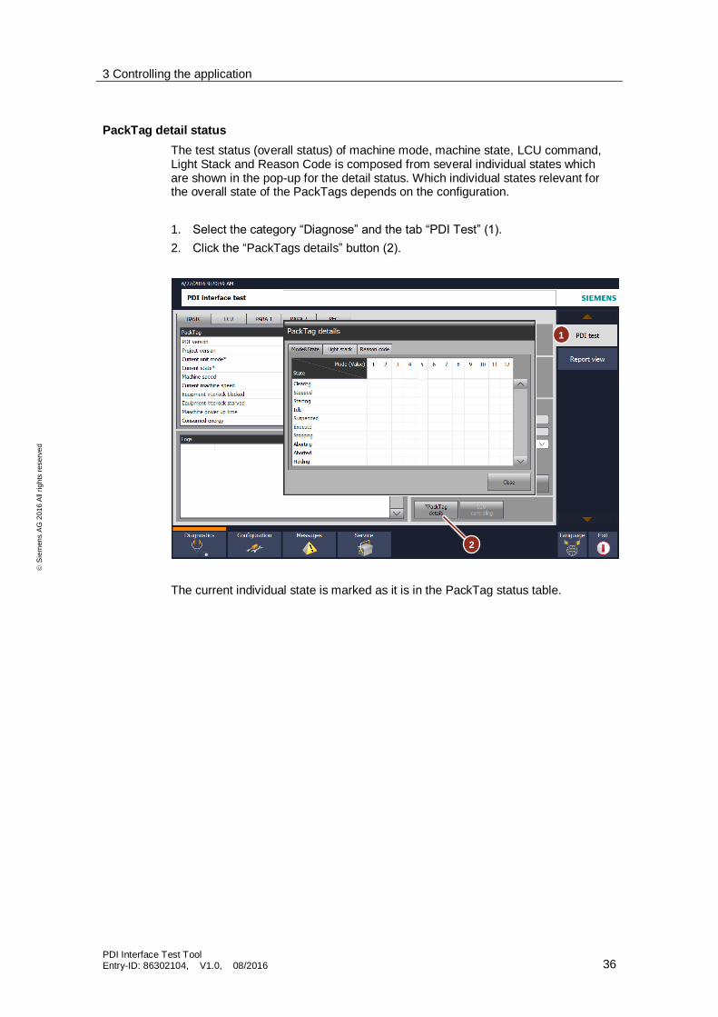
PackTag detail status
The test status (overall status) of machine mode, machine state, LCU command, Light Stack and Reason Code is composed from several individual states which are shown in the pop-up for the detail status. Which individual states relevant for the overall state of the PackTags depends on the configuration.
1. Select the category “Diagnose” and the tab “PDI Test” (1).
2. Click the “PackTags details” button (2).
The current individual state is marked as it is in the PackTag status table.
1
2
3 Controlling the application
PDI Interface Test Tool Entry-ID: 86302104, V1.0, 08/2016 37
S
iem
en
s A
G 2
01
6 A
ll ri
gh
ts r
ese
rve
d
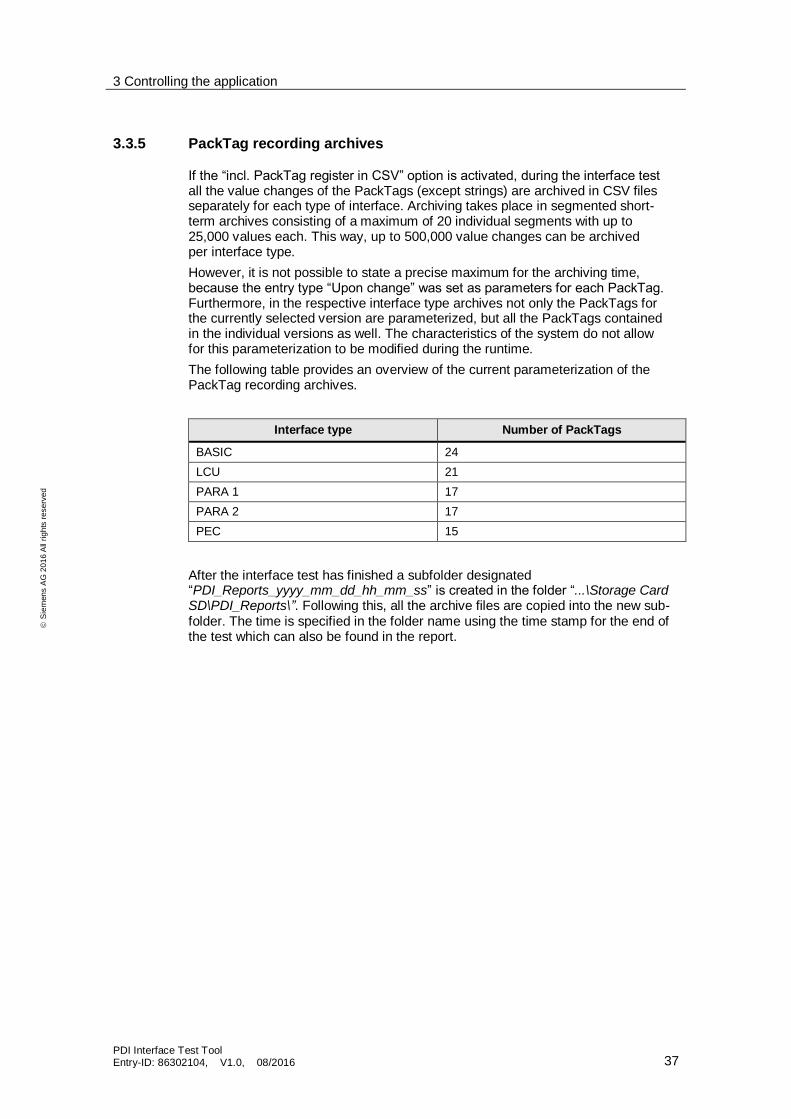
3.3.5 PackTag recording archives
If the “incl. PackTag register in CSV” option is activated, during the interface test all the value changes of the PackTags (except strings) are archived in CSV files separately for each type of interface. Archiving takes place in segmented short-term archives consisting of a maximum of 20 individual segments with up to 25,000 values each. This way, up to 500,000 value changes can be archived per interface type.
However, it is not possible to state a precise maximum for the archiving time, because the entry type “Upon change” was set as parameters for each PackTag. Furthermore, in the respective interface type archives not only the PackTags for the currently selected version are parameterized, but all the PackTags contained in the individual versions as well. The characteristics of the system do not allow for this parameterization to be modified during the runtime.
The following table provides an overview of the current parameterization of the PackTag recording archives.
Interface type Number of PackTags BASIC 24
LCU 21
PARA 1 17
PARA 2 17
PEC 15
After the interface test has finished a subfolder designated “PDI_Reports_yyyy_mm_dd_hh_mm_ss” is created in the folder “...\Storage Card SD\PDI_Reports\”. Following this, all the archive files are copied into the new sub-folder. The time is specified in the folder name using the time stamp for the end of the test which can also be found in the report.
3 Controlling the application
PDI Interface Test Tool Entry-ID: 86302104, V1.0, 08/2016 38
S
iem
en
s A
G 2
01
6 A
ll ri
gh
ts r
ese
rve
d
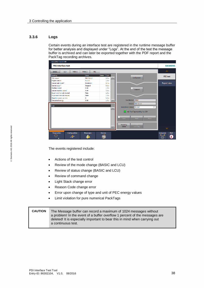
3.3.6 Logs
Certain events during an interface test are registered in the runtime message buffer for better analysis and displayed under “Logs”. At the end of the test the message buffer is archived and can later be exported together with the PDF report and the PackTag recording archives.
The events registered include:
Actions of the test control
Review of the mode change (BASIC and LCU)
Review of status change (BASIC and LCU)
Review of command change
Light Stack change error
Reason Code change error
Error upon change of type and unit of PEC energy values
Limit violation for pure numerical PackTags
CAUTION The Message buffer can record a maximum of 1024 messages without a problem! In the event of a buffer overflow 1 percent of the messages are deleted! It is especially important to bear this in mind when carrying out a continuous test.
3 Controlling the application
PDI Interface Test Tool Entry-ID: 86302104, V1.0, 08/2016 39
S
iem
en
s A
G 2
01
6 A
ll ri
gh
ts r
ese
rve
d
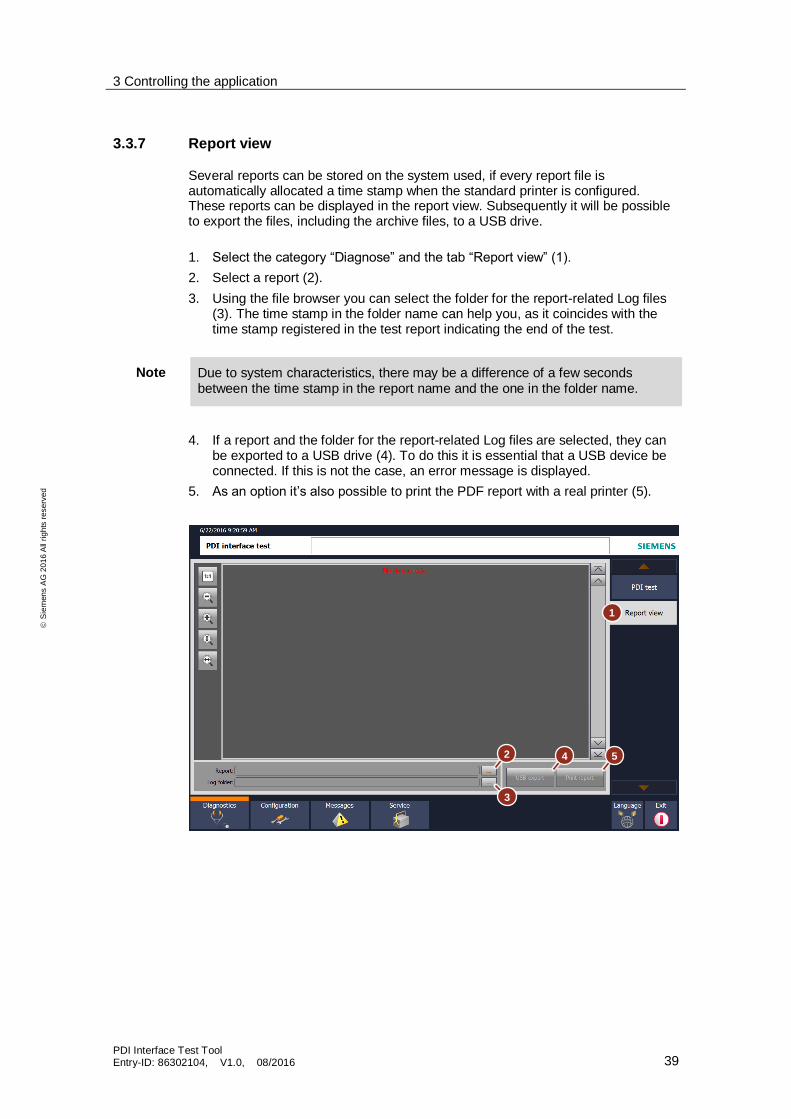
3.3.7 Report view
Several reports can be stored on the system used, if every report file is automatically allocated a time stamp when the standard printer is configured. These reports can be displayed in the report view. Subsequently it will be possible to export the files, including the archive files, to a USB drive.
1. Select the category “Diagnose” and the tab “Report view” (1).
2. Select a report (2).
3. Using the file browser you can select the folder for the report-related Log files (3). The time stamp in the folder name can help you, as it coincides with the time stamp registered in the test report indicating the end of the test.
Note Due to system characteristics, there may be a difference of a few seconds between the time stamp in the report name and the one in the folder name.
4. If a report and the folder for the report-related Log files are selected, they can be exported to a USB drive (4). To do this it is essential that a USB device be connected. If this is not the case, an error message is displayed.
5. As an option it’s also possible to print the PDF report with a real printer (5).
1
2
3
4 5
3 Controlling the application
PDI Interface Test Tool Entry-ID: 86302104, V1.0, 08/2016 40
S
iem
en
s A
G 2
01
6 A
ll ri
gh
ts r
ese
rve
d
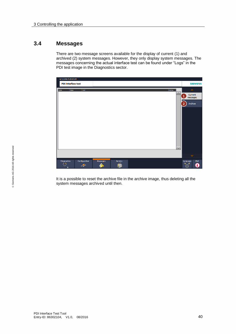
3.4 Messages
There are two message screens available for the display of current (1) and archived (2) system messages. However, they only display system messages. The messages concerning the actual interface test can be found under “Logs” in the PDI test image in the Diagnostics sector.
It is a possible to reset the archive file in the archive image, thus deleting all the system messages archived until then.
1
2
3 Controlling the application
PDI Interface Test Tool Entry-ID: 86302104, V1.0, 08/2016 41
S
iem
en
s A
G 2
01
6 A
ll ri
gh
ts r
ese
rve
d
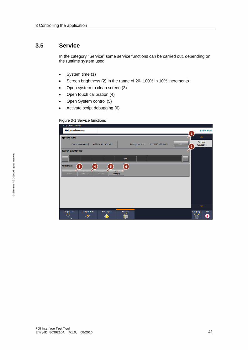
3.5 Service
In the category “Service” some service functions can be carried out, depending on the runtime system used.
System time (1)
Screen brightness (2) in the range of 20- 100% in 10% increments
Open system to clean screen (3)
Open touch calibration (4)
Open System control (5)
Activate script debugging (6)
Figure 3-1 Service functions
1
2
3 4 5 6
4 OPC UA Variables
PDI Interface Test Tool
Entry-ID: 86302104, V1.0, 08/2016 42
Siemens AG 2016 All rights reserved
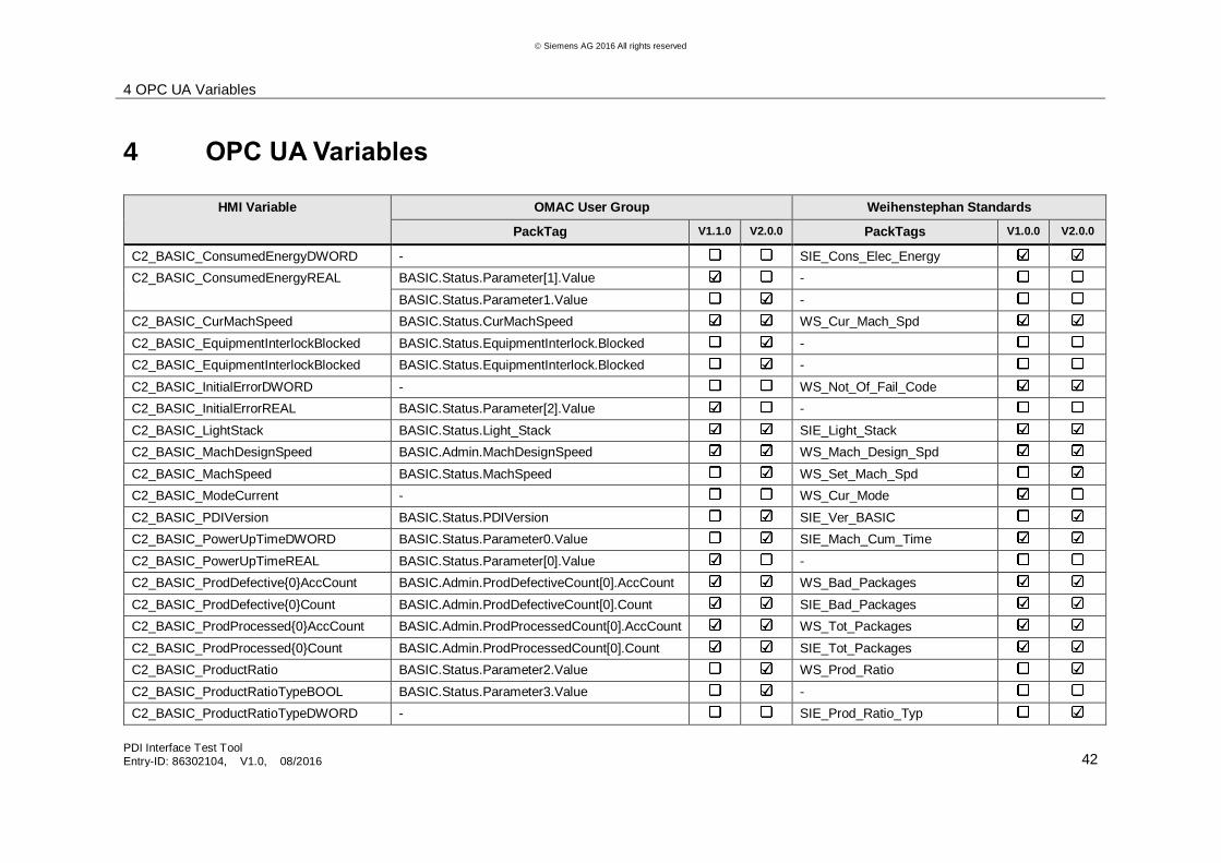
4 OPC UA Variables
HMI Variable OMAC User Group Weihenstephan Standards
PackTag V1.1.0 V2.0.0 PackTags V1.0.0 V2.0.0
C2_BASIC_ConsumedEnergyDWORD - SIE_Cons_Elec_Energy
C2_BASIC_ConsumedEnergyREAL BASIC.Status.Parameter[1].Value -
BASIC.Status.Parameter1.Value -
C2_BASIC_CurMachSpeed BASIC.Status.CurMachSpeed WS_Cur_Mach_Spd
C2_BASIC_EquipmentInterlockBlocked BASIC.Status.EquipmentInterlock.Blocked -
C2_BASIC_EquipmentInterlockBlocked BASIC.Status.EquipmentInterlock.Blocked -
C2_BASIC_InitialErrorDWORD - WS_Not_Of_Fail_Code
C2_BASIC_InitialErrorREAL BASIC.Status.Parameter[2].Value -
C2_BASIC_LightStack BASIC.Status.Light_Stack SIE_Light_Stack
C2_BASIC_MachDesignSpeed BASIC.Admin.MachDesignSpeed WS_Mach_Design_Spd
C2_BASIC_MachSpeed BASIC.Status.MachSpeed WS_Set_Mach_Spd
C2_BASIC_ModeCurrent - WS_Cur_Mode
C2_BASIC_PDIVersion BASIC.Status.PDIVersion SIE_Ver_BASIC
C2_BASIC_PowerUpTimeDWORD BASIC.Status.Parameter0.Value SIE_Mach_Cum_Time
C2_BASIC_PowerUpTimeREAL BASIC.Status.Parameter[0].Value -
C2_BASIC_ProdDefective{0}AccCount BASIC.Admin.ProdDefectiveCount[0].AccCount WS_Bad_Packages
C2_BASIC_ProdDefective{0}Count BASIC.Admin.ProdDefectiveCount[0].Count SIE_Bad_Packages
C2_BASIC_ProdProcessed{0}AccCount BASIC.Admin.ProdProcessedCount[0].AccCount WS_Tot_Packages
C2_BASIC_ProdProcessed{0}Count BASIC.Admin.ProdProcessedCount[0].Count SIE_Tot_Packages
C2_BASIC_ProductRatio BASIC.Status.Parameter2.Value WS_Prod_Ratio
C2_BASIC_ProductRatioTypeBOOL BASIC.Status.Parameter3.Value -
C2_BASIC_ProductRatioTypeDWORD - SIE_Prod_Ratio_Typ
4 OPC UA Variables
PDI Interface Test Tool
Entry-ID: 86302104, V1.0, 08/2016 43
Siemens AG 2016 All rights reserved
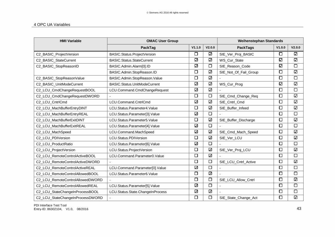
HMI Variable OMAC User Group Weihenstephan Standards
PackTag V1.1.0 V2.0.0 PackTags V1.0.0 V2.0.0
C2_BASIC_ProjectVersion BASIC.Status.ProjectVersion SIE_Ver_Proj_BASIC
C2_BASIC_StateCurrent BASIC.Status.StateCurrent WS_Cur_State
C2_BASIC_StopReasonID BASIC.Admin.Alarm[0].ID SIE_Reason_Code
BASIC.Admin.StopReason.ID SIE_Not_Of_Fail_Group
C2_BASIC_StopReasonValue BASIC.Admin.StopReason.Value -
C2_BASIC_UnitModeCurrent BASIC.Status.UnitModeCurrent WS_Cur_Prog
C2_LCU_CmdChangeRequestBOOL LCU.Command.CmdChangeRequest -
C2_LCU_CmdChangeRequestDWORD - SIE_Cmd_Change_Req
C2_LCU_CntrlCmd LCU.Command.CntrlCmd SIE_Cntrl_Cmd
C2_LCU_MachBufferEntryDINT LCU.Status.Parameter4.Value SIE_Buffer_Infeed
C2_LCU_MachBufferEntryREAL LCU.Status.Parameter[3].Value -
C2_LCU_MachBufferExitDINT LCU.Status.Parameter5.Value SIE_Buffer_Discharge
C2_LCU_MachBufferExitREAL LCU.Status.Parameter[4].Value -
C2_LCU_MachSpeed LCU.Command.MachSpeed SIE_Cmd_Mach_Speed
C2_LCU_PDIVersion LCU.Status.PDIVersion SIE_Ver_LCU
C2_LCU_ProductRatio LCU.Status.Parameter[6].Value -
C2_LCU_ProjectVersion LCU.Status.ProjectVersion SIE_Ver_Proj_LCU
C2_LCU_RemoteControlActiveBOOL LCU.Command.Parameter0.Value -
C2_LCU_RemoteControlActiveDWORD - SIE_LCU_Cntrl_Active
C2_LCU_RemoteControlActiveREAL LCU.Command.Parameter[0].Value -
C2_LCU_RemoteControlAllowedBOOL LCU.Status.Parameter6.Value -
C2_LCU_RemoteControlAllowedDWORD - SIE_LCU_Allow_Cntrl
C2_LCU_RemoteControlAllowedREAL LCU.Status.Parameter[5].Value -
C2_LCU_StateChangeInProcessBOOL LCU.Status.State.ChangeInProcess -
C2_LCU_StateChangeInProcessDWORD - SIE_State_Change_Act
4 OPC UA Variables
PDI Interface Test Tool
Entry-ID: 86302104, V1.0, 08/2016 44
Siemens AG 2016 All rights reserved
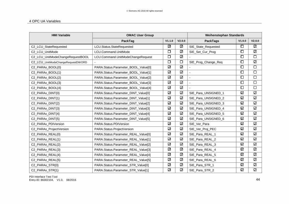
HMI Variable OMAC User Group Weihenstephan Standards
PackTag V1.1.0 V2.0.0 PackTags V1.0.0 V2.0.0
C2_LCU_StateRequested LCU.Status.StateRequested SIE_State_Requested
C2_LCU_UnitMode LCU.Command.UnitMode SIE_Set_Cur_Prog
C2_LCU_UnitModeChangeRequestBOOL LCU.Command.UnitModeChangeRequest -
C2_LCU_UnitModeChangeRequestDWORD - SIE_Prog_Change_Req
C2_PARAx_BOOL{0} PARA.Status.Parameter_BOOL_Value[0] -
C2_PARAx_BOOL{1} PARA.Status.Parameter_BOOL_Value[1] -
C2_PARAx_BOOL{2} PARA.Status.Parameter_BOOL_Value[2] -
C2_PARAx_BOOL{3} PARA.Status.Parameter_BOOL_Value[3] -
C2_PARAx_BOOL{4} PARA.Status.Parameter_BOOL_Value[4] -
C2_PARAx_DINT{0} PARA.Status.Parameter_DINT_Value[0] SIE_Para_UNSIGNED_1
C2_PARAx_DINT{1} PARA.Status.Parameter_DINT_Value[1] SIE_Para_UNSIGNED_2
C2_PARAx_DINT{2} PARA.Status.Parameter_DINT_Value[2] SIE_Para_UNSIGNED_3
C2_PARAx_DINT{3} PARA.Status.Parameter_DINT_Value[3] SIE_Para_UNSIGNED_4
C2_PARAx_DINT{4} PARA.Status.Parameter_DINT_Value[4] SIE_Para_UNSIGNED_5
C2_PARAx_DINT{5} PARA.Status.Parameter_DINT_Value[5] SIE_Para_UNSIGNED_6
C2_PARAx_PDIVersion PARA.Status.PDIVersion SIE_Ver_Para
C2_PARAx_ProjectVersion PARA.Status.ProjectVersion SIE_Ver_Proj_PEC
C2_PARAx_REAL{0} PARA.Status.Parameter_REAL_Value[0] SIE_Para_REAL_1
C2_PARAx_REAL{1} PARA.Status.Parameter_REAL_Value[1] SIE_Para_REAL_2
C2_PARAx_REAL{2} PARA.Status.Parameter_REAL_Value[2] SIE_Para_REAL_3
C2_PARAx_REAL{3} PARA.Status.Parameter_REAL_Value[3] SIE_Para_REAL_4
C2_PARAx_REAL{4} PARA.Status.Parameter_REAL_Value[4] SIE_Para_REAL_5
C2_PARAx_REAL{5} PARA.Status.Parameter_REAL_Value[5] SIE_Para_REAL_6
C2_PARAx_STR{0} PARA.Status.Parameter_STR_Value[0] SIE_Para_STR_1
C2_PARAx_STR{1} PARA.Status.Parameter_STR_Value[1] SIE_Para_STR_2
4 OPC UA Variables
PDI Interface Test Tool
Entry-ID: 86302104, V1.0, 08/2016 45
Siemens AG 2016 All rights reserved
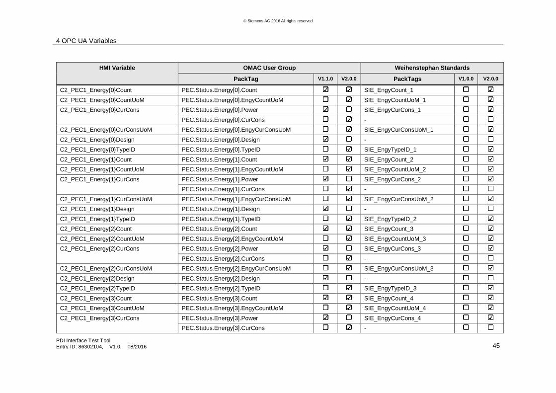
HMI Variable OMAC User Group Weihenstephan Standards
PackTag V1.1.0 V2.0.0 PackTags V1.0.0 V2.0.0
C2_PEC1_Energy{0}Count PEC.Status.Energy[0].Count SIE_EngyCount_1
C2_PEC1_Energy{0}CountUoM PEC.Status.Energy[0].EngyCountUoM SIE_EngyCountUoM_1
C2_PEC1_Energy{0}CurCons PEC.Status.Energy[0].Power SIE_EngyCurCons_1
PEC.Status.Energy[0].CurCons -
C2_PEC1_Energy{0}CurConsUoM PEC.Status.Energy[0].EngyCurConsUoM SIE_EngyCurConsUoM_1
C2_PEC1_Energy{0}Design PEC.Status.Energy[0].Design -
C2_PEC1_Energy{0}TypeID PEC.Status.Energy[0].TypeID SIE_EngyTypeID_1
C2_PEC1_Energy{1}Count PEC.Status.Energy[1].Count SIE_EngyCount_2
C2_PEC1_Energy{1}CountUoM PEC.Status.Energy[1].EngyCountUoM SIE_EngyCountUoM_2
C2_PEC1_Energy{1}CurCons PEC.Status.Energy[1].Power SIE_EngyCurCons_2
PEC.Status.Energy[1].CurCons -
C2_PEC1_Energy{1}CurConsUoM PEC.Status.Energy[1].EngyCurConsUoM SIE_EngyCurConsUoM_2
C2_PEC1_Energy{1}Design PEC.Status.Energy[1].Design -
C2_PEC1_Energy{1}TypeID PEC.Status.Energy[1].TypeID SIE_EngyTypeID_2
C2_PEC1_Energy{2}Count PEC.Status.Energy[2].Count SIE_EngyCount_3
C2_PEC1_Energy{2}CountUoM PEC.Status.Energy[2].EngyCountUoM SIE_EngyCountUoM_3
C2_PEC1_Energy{2}CurCons PEC.Status.Energy[2].Power SIE_EngyCurCons_3
PEC.Status.Energy[2].CurCons -
C2_PEC1_Energy{2}CurConsUoM PEC.Status.Energy[2].EngyCurConsUoM SIE_EngyCurConsUoM_3
C2_PEC1_Energy{2}Design PEC.Status.Energy[2].Design -
C2_PEC1_Energy{2}TypeID PEC.Status.Energy[2].TypeID SIE_EngyTypeID_3
C2_PEC1_Energy{3}Count PEC.Status.Energy[3].Count SIE_EngyCount_4
C2_PEC1_Energy{3}CountUoM PEC.Status.Energy[3].EngyCountUoM SIE_EngyCountUoM_4
C2_PEC1_Energy{3}CurCons PEC.Status.Energy[3].Power SIE_EngyCurCons_4
PEC.Status.Energy[3].CurCons -
4 OPC UA Variables
PDI Interface Test Tool
Entry-ID: 86302104, V1.0, 08/2016 46
Siemens AG 2016 All rights reserved
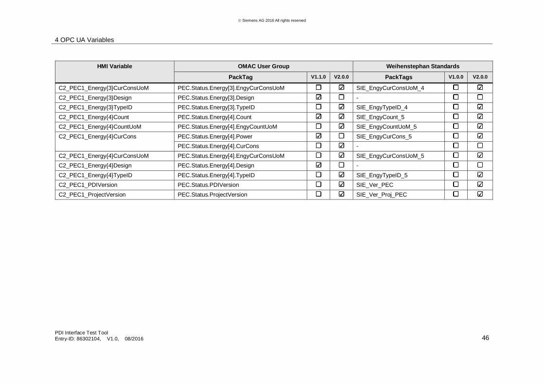
HMI Variable OMAC User Group Weihenstephan Standards
PackTag V1.1.0 V2.0.0 PackTags V1.0.0 V2.0.0
C2_PEC1_Energy{3}CurConsUoM PEC.Status.Energy[3].EngyCurConsUoM SIE_EngyCurConsUoM_4
C2_PEC1_Energy{3}Design PEC.Status.Energy[3].Design -
C2_PEC1_Energy{3}TypeID PEC.Status.Energy[3].TypeID SIE_EngyTypeID_4
C2_PEC1_Energy{4}Count PEC.Status.Energy[4].Count SIE_EngyCount_5
C2_PEC1_Energy{4}CountUoM PEC.Status.Energy[4].EngyCountUoM SIE_EngyCountUoM_5
C2_PEC1_Energy{4}CurCons PEC.Status.Energy[4].Power SIE_EngyCurCons_5
PEC.Status.Energy[4].CurCons -
C2_PEC1_Energy{4}CurConsUoM PEC.Status.Energy[4].EngyCurConsUoM SIE_EngyCurConsUoM_5
C2_PEC1_Energy{4}Design PEC.Status.Energy[4].Design -
C2_PEC1_Energy{4}TypeID PEC.Status.Energy[4].TypeID SIE_EngyTypeID_5
C2_PEC1_PDIVersion PEC.Status.PDIVersion SIE_Ver_PEC
C2_PEC1_ProjectVersion PEC.Status.ProjectVersion SIE_Ver_Proj_PEC
5 Related literature
PDI Interface Test Tool Entry-ID: 86302104, V1.0, 08/2016 47
S
iem
en
s A
G 2
01
6 A
ll ri
gh
ts r
ese
rve
d
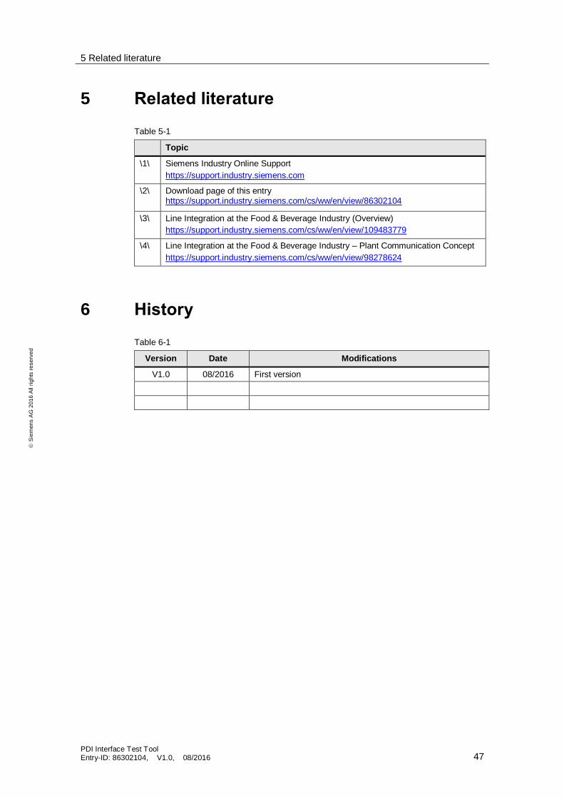
5 Related literature
Table 5-1
Topic
\1\ Siemens Industry Online Support
https://support.industry.siemens.com
\2\ Download page of this entry https://support.industry.siemens.com/cs/ww/en/view/86302104
\3\ Line Integration at the Food & Beverage Industry (Overview)
https://support.industry.siemens.com/cs/ww/en/view/109483779
\4\ Line Integration at the Food & Beverage Industry – Plant Communication Concept
https://support.industry.siemens.com/cs/ww/en/view/98278624
6 History
Table 6-1
Version Date Modifications
V1.0 08/2016 First version