Application description y 09/20142014 Parts Catcher with ... · Application description y...
24
http://support.automation.siemens.com/WW/view/en/88992007 Application description 09/20142014 Parts Catcher with Sub – Spindle SINUMERIK 828D
Transcript of Application description y 09/20142014 Parts Catcher with ... · Application description y...

http://support.automation.siemens.com/WW/view/en/88992007
Application description 09/20142014
Parts Catcher with Sub –SpindleSINUMERIK 828D

Warranty and liability
Parts catcher with sub spindleEntry-ID: 88992007, V1.0, 09/2014 2
Siem
ens
AG20
14Al
lrig
hts
rese
rved
Warranty and liability
Note The Application Examples are not binding and do not claim to be completeregarding the circuits shown, equipping and any eventuality. The ApplicationExamples do not represent customer-specific solutions. They are only intendedto provide support for typical applications. You are responsible for ensuring thatthe described products are used correctly. These application examples do notrelieve you of the responsibility to use safe practices in application, installation,operation and maintenance. When using these Application Examples, yourecognize that we cannot be made liable for any damage/claims beyond theliability clause described. We reserve the right to make changes to theseApplication Examples at any time without prior notice.If there are any deviations between the recommendations provided in theseapplication examples and other Siemens publications – e.g. Catalogs – thecontents of the other documents have priority.
We do not accept any liability for the information contained in this document.
Any claims against us – based on whatever legal reason – resulting from the use ofthe examples, information, programs, engineering and performance data etc.,described in this Application Example shall be excluded. Such an exclusion shallnot apply in the case of mandatory liability, e.g. under the German Product LiabilityAct (“Produkthaftungsgesetz”), in case of intent, gross negligence, or injury of life,body or health, guarantee for the quality of a product, fraudulent concealment of adeficiency or breach of a condition which goes to the root of the contract(“wesentliche Vertragspflichten”). The damages for a breach of a substantialcontractual obligation are, however, limited to the foreseeable damage, typical forthe type of contract, except in the event of intent or gross negligence or injury tolife, body or health. The above provisions do not imply a change of the burden ofproof to your detriment.
Any form of duplication or distribution of these Application Examples or excerptshereof is prohibited without the expressed consent of Siemens Industry Sector.
Securityinforma-tion
Siemens provides products and solutions with industrial security functions thatsupport the secure operation of plants, solutions, machines, equipment and/ornetworks. They are important components in a holistic industrial securityconcept. With this in mind, Siemens’ products and solutions undergo continuousdevelopment. Siemens recommends strongly that you regularly check forproduct updates.
For the secure operation of Siemens products and solutions, it is necessary totake suitable preventive action (e.g. cell protection concept) and integrate eachcomponent into a holistic, state-of-the-art industrial security concept. Third-partyproducts that may be in use should also be considered. For more informationabout industrial security, visit http://www.siemens.com/industrialsecurity.
To stay informed about product updates as they occur, sign up for a product-specific newsletter. For more information, visithttp://support.automation.siemens.com.

Table of contents
Parts catcher with sub spindleEntry-ID: 88992007, V1.0, 09/2014 3
Siem
ens
AG20
14Al
lrig
hts
rese
rved
Table of contentsWarranty and liability ................................................................................................... 2
1.1 Parts Catcher at Turning Machines with Sub Spindles ........................ 41.2 Overview............................................................................................... 4
2 Solution............................................................................................................... 5
2.1 Solution overview ................................................................................. 52.2 Hardware and Software Components .................................................. 62.2.1 Validity .................................................................................................. 6
3 Function mechanisms ....................................................................................... 7
3.1 General overview ................................................................................. 73.2 Parts Catcher positioning based on Chuck Data ................................. 83.2.1 Details of the Position Calculation ........................................................ 93.3 Parts Catcher positioning based on Cut off Position .......................... 113.3.1 Details of the Position Calculation ...................................................... 123.4 Cycle _PCATCH.SPF ......................................................................... 14
4 Installation and Startup ................................................................................... 15
4.1 Configuration of the Machine Data ..................................................... 154.2 Configuration of the GUD MGUD.DEF ............................................... 154.3 Modify and Copy Parts Catcher Cycle _PCATCH.SPF ..................... 164.4 Modify and Copy Parts Catcher Setup Screen .................................. 164.5 Configuration of CUST_TECHCYC.SPF Cycle.................................. 174.6 Setup the Chuck and Part Catcher Dimensions ................................ 18
5 Operation of the application ........................................................................... 19
5.1 Overview............................................................................................. 195.2 Operation in ShopTurn ....................................................................... 195.3 Operation in programGuide with Cycle Support ................................ 205.4 Operation in programGuide – G-Code ............................................... 21
6 Related literature ............................................................................................. 23
7 Contact.............................................................................................................. 23
8 History............................................................................................................... 23

2 Solution1.1 Parts Catcher at Turning Machines with Sub Spindles
Parts catcher with sub spindleEntry-ID: 88992007, V1.0, 09/2014 4
Siem
ens
AG20
14Al
lrig
hts
rese
rved
1.1 Parts Catcher at Turning Machines withSub Spindles
1.2 Overview
IntroductionAt turning machines the parts catcher is a common or optional feature. It can befound on almost all types of horizontal turning machine for mass production of lightor medium weight work pieces. Usually it is a simple mechanical arm driven by asmall motor or hydraulics. The manufacturer also provides M-Codes to start themotion of that arm from a part program. For Standard machines the setup of the M-Codes and the corresponding PLC Logic is very simple and is not part of thisdocument.On turning machines with sub spindle the parts catcher behaves almost the same.It is can be mounted to the moveable slide of the sub spindle and also controlledby M-Codes. The only special case which can occur is the cut off sequence at themain spindle. Without special preparation the work piece will fall down into the chipcontainer. Under some circumstances this can lead already to a damage of themanufactured work piece.
This document will show a sample solutions for using the parts catcher of the subspindle with a simple setup screen.
Overview of the automation taskThe figure below provides an overview of the automation task.
Figure 2-1
?

2 Solution2.1 Solution overview
Parts catcher with sub spindleEntry-ID: 88992007, V1.0, 09/2014 5
Siem
ens
AG20
14Al
lrig
hts
rese
rved
2 Solution2.1 Solution overview
DisplayThe solution for the parts catcher is a cycle, which calculates automatically thecorrect position. After that the Controller will automatically position the partscatcher to that calculated position catches the work piece and after that movesback to the parking position.
The following figure displays the cut off position:Figure 2-1
If all boundary conditions are fulfilled and the machine is setup correctly, the cyclewill also check for crash conditions. Never the less, a carful testing of that functionis necessary.

2 Solution2.2 Hardware and Software Components
Parts catcher with sub spindleEntry-ID: 88992007, V1.0, 09/2014 6
Siem
ens
AG20
14Al
lrig
hts
rese
rved
AdvantagesThis application offers you the following advantages:
Automatically parts catcher positioning in Shop Turn/Program Guide Easy Setup Screen for Parts Catcher Dimensions Reduced Programming Time
Required knowledge Basic Knowledge of Commissioning and Service of SINUMERIK 828D or
840D sl with SINAMICS S120 Basic Knowledge in NC Programming and GUD’s Basic Knowledge in Commissioning of ShopTurn Basic Knowledge in Commissioning of RunMyScreen Basic Knowledge in Machine Operation
2.2 Hardware and Software Components
2.2.1 Validity
The application was generated with SINUMERIK 828D Turning Edition andSW2.6/2.7 on PPU280.1. Basically it should work with all Software and HardwareVersions of SINUMERIK 828D and SINUMERIK 840D sl.

3 Function mechanisms3.1 General overview
Parts catcher with sub spindleEntry-ID: 88992007, V1.0, 09/2014 7
Siem
ens
AG20
14Al
lrig
hts
rese
rved
3 Function mechanisms3.1 General overview
This figure shows the general process of the Cut off Cycle.
Figure 3-1
StartCut Off
Sequence
Tool ChangeCut Off Tool
Position PartCatcher
Cut Off untilTravel Out
Depth
M-Code PartCatcherAdvance
FinishCut Off
Move PartCatcherHome
M-Code PartCatcherRetract
FinishCut Off
Sequence
For determining the correct position for the parts catcher during cut off, 2 ways arepossible:1. Positioning based on Chuck Data and Actual Work Offset2. Positioning on Actual Tools WCS Position and actual Work Offset
The Difference between these 2 methods is explained in the next chapters. Finallythe advantages of both are combined in one cycle!

3 Function mechanisms3.2 Parts Catcher positioning based on Chuck Data
Parts catcher with sub spindleEntry-ID: 88992007, V1.0, 09/2014 8
Siem
ens
AG20
14Al
lrig
hts
rese
rved
3.2 Parts Catcher positioning based on Chuck Data
For a fully understanding of the function some variables need to be defined.Refer to the following figure for variable naming.
Figure 3-2
Table 3-1
Variable Unit MD Description
ZC1 [mm]/[inch] MD53240[0] Chuck Dimension from Main Spindle Nose to the end ofthe chuck in Z-Axis Direction. To be defined in theStandard Chuck Data Screen
ZS1 [mm]/[inch] MD53240[1] Jaw Dimension from Main Spindle Nose to the end of thechuck in Z-Axis Direction. To be defined in the StandardChuck Data Screen
Lwp [mm]/[inch] Resultant length of Offset minus ZC1 and ZS1. Usedonly for explanation.
_SPC [mm]/[inch] GUD Length of the parts catcher pocket. Has to be defined byOEM or User.
_LPC [mm]/[inch] GUD Total Distance from Sub Spindle Nose to the end of theparts catcher. Has to be defined by OEM or User.
_SG [mm]/[inch] GUD Safety Gap for avoiding a crash between Main SpindleChuck/Jaw and the extended Parts Catcher. Has to bedefined by OEM or User.
Offset [mm]/[inch] Z-Axis Dimension in MCS(Machine Coordinate System)for Work Piece Reference Point , where WCS(WorkPiece Coordinate System) Z=0
C1 Main Spindle of the machineC3 Sub Spindle of the machine

3 Function mechanisms3.2 Parts Catcher positioning based on Chuck Data
Parts catcher with sub spindleEntry-ID: 88992007, V1.0, 09/2014 9
Siem
ens
AG20
14Al
lrig
hts
rese
rved
Variable Unit MD Description
LSSP Linear Axis which moves the Sub Spindle
3.2.1 Details of the Position Calculation
For calculating the correct Position for the linear axis of the sub spindle 2 Casesmust be considered. It must be avoided that the Parts Catcher touches the runningMain Spindle chuck.
Case 1: Lwp >_SPC
The Length of the Work Piece (Lwp) outside of the Main Spindle Chuck Jaws isbigger than the length of the Parts Catchers Pocket (_SPC)!The right edge of the Parts Catchers Pocket is positioned at active Work OffsetsZ=0
Figure 3-3
Figure 1: Case 1, Parts Catcher is shorter than Work Piece
Formula for length of Lwp:
110 SCWP ZZZOffsetL
Formula for Position of LSSP-Axis:
SPCLPCZOffsetLSSPPos __0

3 Function mechanisms3.2 Parts Catcher positioning based on Chuck Data
Parts catcher with sub spindleEntry-ID: 88992007, V1.0, 09/2014 10
Siem
ens
AG20
14Al
lrig
hts
rese
rved
Case 2: Lwp <_SPC
The Length of the Parts Catchers Pocket is bigger than the length of the WorkPiece outside of the Main Spindle Chuck Jaws!The left edge of the Parts Catchers Pocket is positioned at the Main Spindle ChuckJaw plus a safety distance!
Figure 3-4
Figure 2: Case 2, Parts Catcher is longer than Work Piece
Formula for length of Lwp:
110 SCWP ZZZOffsetL
Formula for Position of LSSP-Axis:
SGLPCZZLSSP SCPos __11

3 Function mechanisms3.3 Parts Catcher positioning based on Cut off Position
Parts catcher with sub spindleEntry-ID: 88992007, V1.0, 09/2014 11
Siem
ens
AG20
14Al
lrig
hts
rese
rved
Advantages and Disadvantages
Table 3-2
Advantage Disadvantage
Crash Protection for Sub Spindle Can be used in all kind of programs (ShopTurn,
programGuide, G-Code) and cut offsequences
Chuck Dimension Setup must be setup correct Parts Catcher Dimensions must be setup
correctly Position is not the exact cut off position
3.3 Parts Catcher positioning based on Cut off Position
For a fully understanding of the function some variables need to be defined.Refer to the following figure for variable naming.
Figure 3-5
Table 3-3
Variable Unit MD Description
ZC1 [mm]/[inch] MD53240[0] Chuck Dimension from Main Spindle Nose to the end ofthe chuck in Z-Axis Direction. To be defined in theStandard Chuck Data Screen
ZS1 [mm]/[inch] MD53240[1] Jaw Dimension from Main Spindle Nose to the end of the

3 Function mechanisms3.3 Parts Catcher positioning based on Cut off Position
Parts catcher with sub spindleEntry-ID: 88992007, V1.0, 09/2014 12
Siem
ens
AG20
14Al
lrig
hts
rese
rved
Variable Unit MD Descriptionchuck in Z-Axis Direction. To be defined in the StandardChuck Data Screen
Lwp [mm]/[inch] Resultant length of Offset minus ZC1 and ZS1. Usedonly for explanation.
_SPC [mm]/[inch] GUD Length of the parts catcher pocket. Has to be defined byOEM or User.
_LPC [mm]/[inch] GUD Total Distance from Sub Spindle Nose to the end of theparts catcher. Has to be defined by OEM or User.
_SG [mm]/[inch] GUD Safety Gap for avoiding a crash between Main SpindleChuck/Jaw and the extended Parts Catcher. Has to bedefined by OEM or User.
Offset [mm]/[inch] Z-Axis Dimension in MCS(Machine Coordinate System)for Work Piece Reference Point , where WCS(WorkPiece Coordinate System) Z=0
C1 Main Spindle of the machineC3 Sub Spindle of the machineLSSP Linear Axis which moves the Sub Spindle$AA_IW[Z] [mm]/[inch] System
VariableActual WCS Position of the Z-Axis. Here used at the CutOff Position.
3.3.1 Details of the Position Calculation
For calculating the correct Position the Actual Z-Axis WCS Value ($AA_IW[Z]) isused. Before Shop Turn Positions the Parts Catcher, it already has positioned theCut Off Tool to the Cut Off position. This value is used as reference for the axispositioning of the Sub Spindle. The left edge of the Parts Catcher is positioned tothat position.

3 Function mechanisms3.3 Parts Catcher positioning based on Cut off Position
Parts catcher with sub spindleEntry-ID: 88992007, V1.0, 09/2014 13
Siem
ens
AG20
14Al
lrig
hts
rese
rved
Figure 3-6
Figure 3: Cut Off Position of the Work Piece
Formula for Position of LSSP -Axis:
LPCZIWAAZOffsetLSSPPos _][_$0
NOTICE $AA_IW[Z] is in WCS and usually smaller than 0
3 Function mechanisms3.4 Cycle _PCATCH.SPF
Parts catcher with sub spindleEntry-ID: 88992007, V1.0, 09/2014 14
Siem
ens
AG20
14Al
lrig
hts
rese
rved
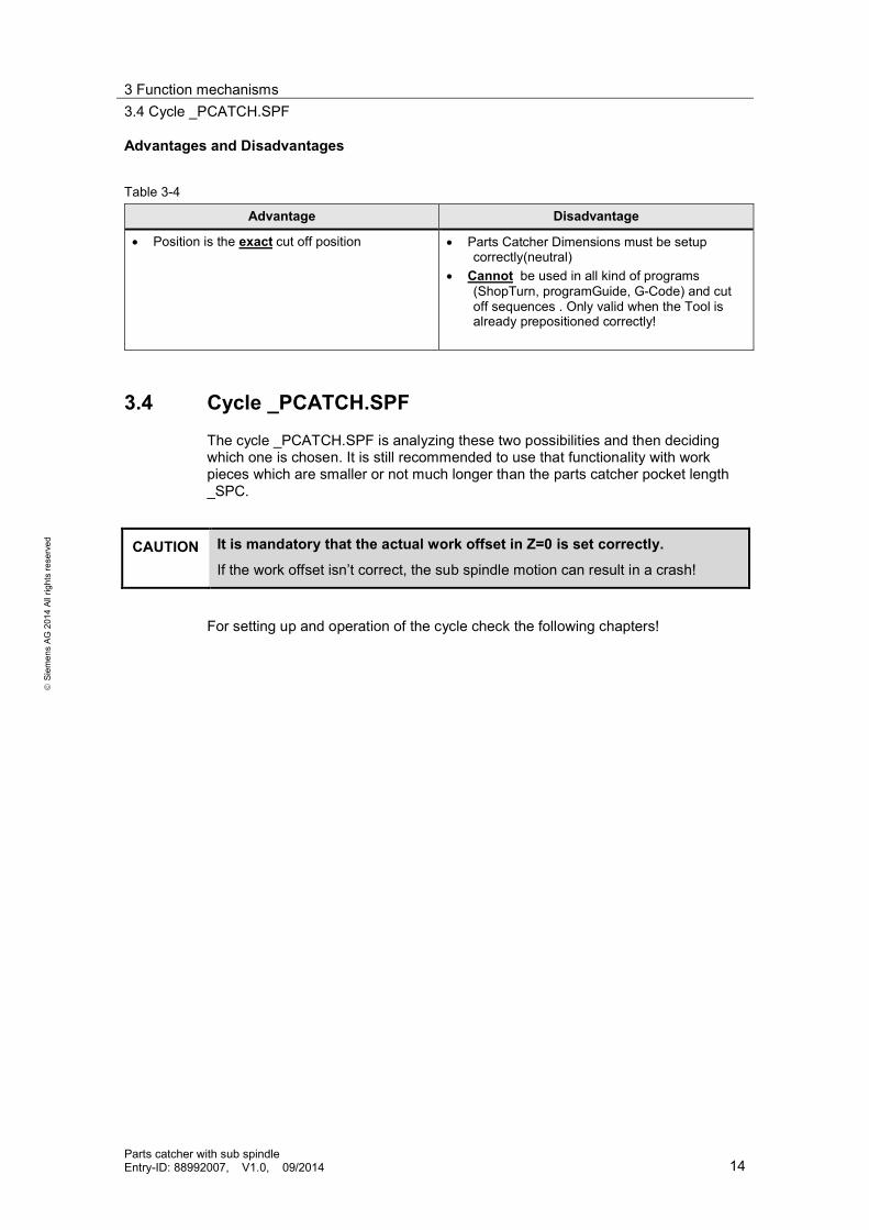
Advantages and Disadvantages
Table 3-4
Advantage Disadvantage
Position is the exact cut off position Parts Catcher Dimensions must be setupcorrectly(neutral)
Cannot be used in all kind of programs(ShopTurn, programGuide, G-Code) and cutoff sequences . Only valid when the Tool isalready prepositioned correctly!
3.4 Cycle _PCATCH.SPF
The cycle _PCATCH.SPF is analyzing these two possibilities and then decidingwhich one is chosen. It is still recommended to use that functionality with workpieces which are smaller or not much longer than the parts catcher pocket length_SPC.
CAUTION It is mandatory that the actual work offset in Z=0 is set correctly.
If the work offset isn’t correct, the sub spindle motion can result in a crash!
For setting up and operation of the cycle check the following chapters!

4 Installation and Startup4.1 Configuration of the Machine Data
Parts catcher with sub spindleEntry-ID: 88992007, V1.0, 09/2014 15
Siem
ens
AG20
14Al
lrig
hts
rese
rved
4 Installation and Startup
Installation of hardware is not needed. A fully functional parts catcher is required.For configuring the functionality of the Parts Catcher the following Steps have to beexecuted:
1. Enable Parts Catcher in the Machine Data for ShopTurn2. Create or modify GUD(MGUD.DEF)3. Modify and copy Parts Catcher Cycle(_PCATCH.SPF)4. Modify and copy Parts Catcher Setup Screen(pcatch.com)5. Edit the CUST_TECHCYC for Shop Turn
4.1 Configuration of the Machine DataTable 4-1
No. Instruction Remarks
1. Set MD52218 bit 1 to 1 This bit enables the Parts CatcherSelection in the Cut Off Cycle Screen
2. Check MD52206[<index>] for correct setup of MainSpindle, Sub Spindle and Linear Axis of Sub Spindle
Main Spindle Value 3Sub Spindle Value 5Linear Axis of Sub Spindle Value 7
4.2 Configuration of the GUD MGUD.DEFTable 4-2
No. Instruction Remarks
1. Open the sample file MGUD.DEF with an editor.2. Modify or Merge to your Controllers Environment3. Copy the file to the DEF folder4. Activate the GUD
The Sample Application file can be found as attachment of this Application Noteand the Source Code can be seen here:
DEF CHAN REAL PHU 2 _POCKET_LENGTHDEF CHAN REAL PHU 2 _PARTCATCHER_LENGTHDEF CHAN REAL PHU 2 _SGM30
NOTICE PHU 2defines a variable as a Physical Variable of Distance. In case of changingthe system MD10240 $MN_SCALING_SYSTEM_IS_METRIC, the value ofthose variables will be automatically converted between inch and metric.
4 Installation and Startup4.3 Modify and Copy Parts Catcher Cycle _PCATCH.SPF
Parts catcher with sub spindleEntry-ID: 88992007, V1.0, 09/2014 16
Siem
ens
AG20
14Al
lrig
hts
rese
rved
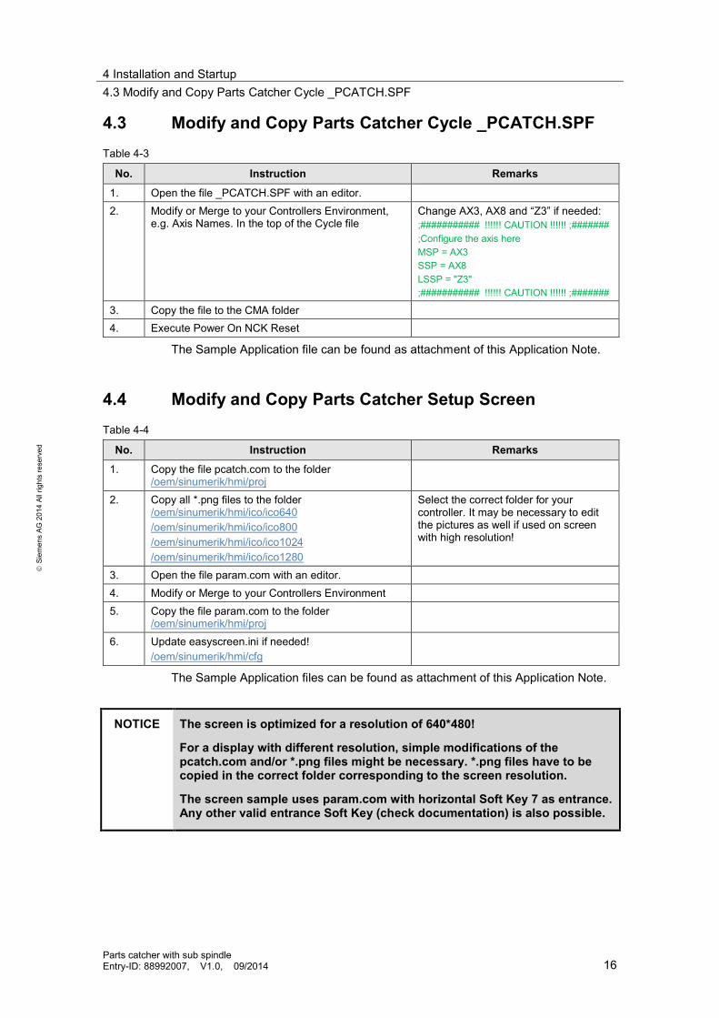
4.3 Modify and Copy Parts Catcher Cycle _PCATCH.SPFTable 4-3
No. Instruction Remarks
1. Open the file _PCATCH.SPF with an editor.2. Modify or Merge to your Controllers Environment,
e.g. Axis Names. In the top of the Cycle fileChange AX3, AX8 and “Z3” if needed:;########### !!!!!! CAUTION !!!!!! ;#######;Configure the axis hereMSP = AX3SSP = AX8LSSP = "Z3";########### !!!!!! CAUTION !!!!!! ;#######
3. Copy the file to the CMA folder4. Execute Power On NCK Reset
The Sample Application file can be found as attachment of this Application Note.
4.4 Modify and Copy Parts Catcher Setup ScreenTable 4-4
No. Instruction Remarks
1. Copy the file pcatch.com to the folder/oem/sinumerik/hmi/proj
2. Copy all *.png files to the folder/oem/sinumerik/hmi/ico/ico640/oem/sinumerik/hmi/ico/ico800/oem/sinumerik/hmi/ico/ico1024/oem/sinumerik/hmi/ico/ico1280
Select the correct folder for yourcontroller. It may be necessary to editthe pictures as well if used on screenwith high resolution!
3. Open the file param.com with an editor.4. Modify or Merge to your Controllers Environment5. Copy the file param.com to the folder
/oem/sinumerik/hmi/proj
6. Update easyscreen.ini if needed!/oem/sinumerik/hmi/cfg
The Sample Application files can be found as attachment of this Application Note.
NOTICE The screen is optimized for a resolution of 640*480!
For a display with different resolution, simple modifications of thepcatch.com and/or *.png files might be necessary. *.png files have to becopied in the correct folder corresponding to the screen resolution.
The screen sample uses param.com with horizontal Soft Key 7 as entrance.Any other valid entrance Soft Key (check documentation) is also possible.

4 Installation and Startup4.5 Configuration of CUST_TECHCYC.SPF Cycle
Parts catcher with sub spindleEntry-ID: 88992007, V1.0, 09/2014 17
Siem
ens
AG20
14Al
lrig
hts
rese
rved
4.5 Configuration of CUST_TECHCYC.SPF Cycle
Table 4-5
No. Instruction Remarks
1. Open the CUST_TECHCYC.SPF2. Go to the mark “_M100” and add the cycle call for
_PCATCH.SPF_M100: ; Position receptacle before cut-offPCATCH
3. Go to the mark “_M101” and check the M-Code forengaging the Parts Catcher. Modify if needed.
_M101: ; Open receptacle for cut-offMyyy
4. Go to the mark “_M102” and check the M-Code forretracting the Parts Catcher. Before this M-Codeadd the moving Parts Catcher Home command!Modify if needed.
_M102: ; Close receptacle after cut-offG75 FP=1 <Your AxisY>=0Mxxx
CAUTION It is considered that the Fix Point 1 (G75) is the Position for emptying theParts Catcher Pocket to the bucket!
If your machine layout is different, or the Fix Point 1 is used already, change thatsequence!

4 Installation and Startup4.6 Setup the Chuck and Part Catcher Dimensions
Parts catcher with sub spindleEntry-ID: 88992007, V1.0, 09/2014 18
Siem
ens
AG20
14Al
lrig
hts
rese
rved
4.6 Setup the Chuck and Part Catcher Dimensions
Table 4-6
No. Instruction Remarks
1. Change to Machine Area Offset
2. Select the Soft Key “Setting Data” and then “Spindlechuck data”
3. Setup the Chuck Dimensions correctly for Main andSub Spindle
4. Press the Soft Key “Operating Parameter”
5. Setup the Parameter for Parts Catcher Dimensions

5 Operation of the application5.1 Overview
Parts catcher with sub spindleEntry-ID: 88992007, V1.0, 09/2014 19
Siem
ens
AG20
14Al
lrig
hts
rese
rved
5 Operation of the application5.1 Overview
There are different ways of operating the parts catcher in a machine. This chapter will showyour 3 different Methods of operating. They are considered as sample and may needadjusting by the operator! The Basic operation is pretty similar.
Operation Methods:3. Fully Automated Operation by the System in ShopTurn4. Operation in programGuide with Cycle Support5. Operation in programGuide with G-Code
5.2 Operation in ShopTurn
Here the short description how to select the cycle in ShopTurn.
Table 5-1
Nr. Action Remarks
1. In your ShopTurn program pressSoft Key “Turning” and then select“Cutoff”
2. Go to the field Parts Gripper andSelect yes.
Modify all other Parametersaccording your cut off process andthen press Soft Key “Accept”
3. Execute your Program
The system will call the Cycle at the correct moment in your cut off sequenceautomatically!
5 Operation of the application5.3 Operation in programGuide with Cycle Support
Parts catcher with sub spindleEntry-ID: 88992007, V1.0, 09/2014 20
Siem
ens
AG20
14Al
lrig
hts
rese
rved
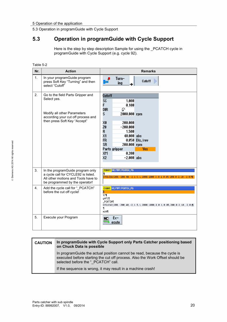
5.3 Operation in programGuide with Cycle SupportHere is the step by step description Sample for using the _PCATCH cycle inprogramGuide with Cycle Support (e.g. cycle 92).
Table 5-2
Nr. Action Remarks
1. In your programGuide programpress Soft Key “Turning” and thenselect “Cutoff”
2. Go to the field Parts Gripper andSelect yes.
Modify all other Parametersaccording your cut off process andthen press Soft Key “Accept”
3. In the programGuide program onlya cycle call for CYCLE92 is listed.All other motions and Tools have tobe programmed by the operator!
4. Add the cycle call for “_PCATCH”before the cut off cycle!
5. Execute your Program
CAUTION In programGuide with Cycle Support only Parts Catcher positioning basedon Chuck Data is possible
In programGuide the actual position cannot be read, because the cycle isexecuted before starting the cut off process. Also the Work Offset should beselected before the “_PCATCH” call.
If the sequence is wrong, it may result in a machine crash!

5 Operation of the application5.4 Operation in programGuide – G-Code
Parts catcher with sub spindleEntry-ID: 88992007, V1.0, 09/2014 21
Siem
ens
AG20
14Al
lrig
hts
rese
rved
5.4 Operation in programGuide – G-Code
Here is the step by step description Sample for using the _PCATCH cycle inprogramGuide with G-Code only.
Table 5-3
Nr. Action Remarks
1. In your programGuide programyour Cut off sequence
Sample Code:
2. Add the cycle call for “_PCATCH”after the tool prepositioning and
Sample Code:

5 Operation of the application5.4 Operation in programGuide – G-Code
Parts catcher with sub spindleEntry-ID: 88992007, V1.0, 09/2014 22
Siem
ens
AG20
14Al
lrig
hts
rese
rved
Nr. Action Remarksbefore the cut off sequence starts!
3. Execute your Program

6 Related literature
Parts catcher with sub spindleEntry-ID: 88992007, V1.0, 09/2014 23
Siem
ens
AG20
14Al
lrig
hts
rese
rved
6 Related literatureTable 6-1
Topic Title / Link
\1\ Siemens IndustryOnline Support
http://support.automation.siemens.com
\2\ Download page ofthis entry
http://support.automation.siemens.com/WW/view/en/88992007
\3\ SINUMERIK 840D sl / 828DFundamentalsProgramming Manual
SINUMERIK 840D slCNC Commissioning: NC, PLC,DriveCommissioning Manual
SINUMERIK 828DTurning and MillingCommissioning Manual
SINUMERIK 840D slBasesoftware and operating softwareCommissioning Manual
SINUMERIK 840D sl / 828DJob PlanningProgramming Manual
7 ContactSiemens AGIndustry SectorI DT MC PMA APCFrauenauracher Strasse 8091056 ErlangenGermanymailto: [email protected]
8 History
Table 8-1
Version Date Modifications
V1.0 MM/YYYY First version

8 History
Parts catcher with sub spindleEntry-ID: 88992007, V1.0, 09/2014 24
Siem
ens
AG20
14Al
lrig
hts
rese
rved